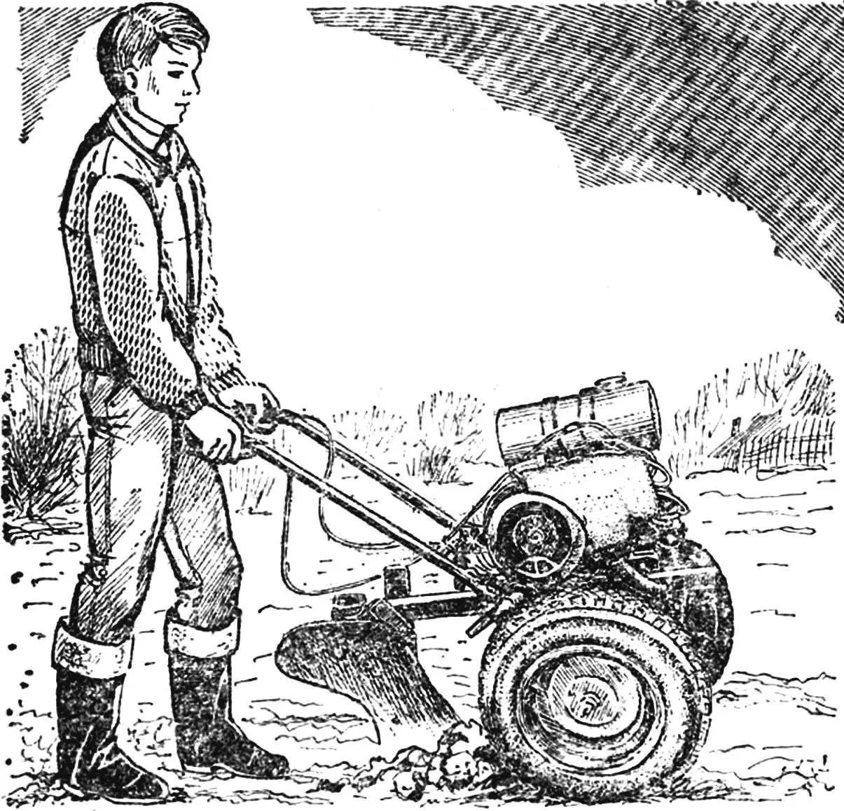
The compact universal self-propelled machine MUSM-1 — that’s what the young craftsmen from the modeling and construction club of agricultural machines at Novokulinskaya Secondary School in Dagestan named their design. With the help of various attachments, it performs plowing, cultivation, sowing, harrowing; mows hay and collects dried grass into windrows and haystacks; transports various loads in a trailer cart, and in winter helps clear snow. From the power take-off shaft, other mechanized tools can be driven — a circular saw, a drill, a water pump.
Such a wide range of work became possible thanks to the versatility of the design, combining the advantages of a microtractor, a walk-behind tractor, and a motor drive. The club leader K. M. Kurbalayev tells in detail about the machine’s design.
In walk-behind tractor designs, a two-wheel layout is most common. It provides the machine with sufficient stability and good maneuverability. However, for work on open areas — in the field, on meadows — three- and four-wheel schemes, characteristic of microtractors, are preferable. The driver, mounted on the machine, controls it with greater convenience and precision, and most importantly, the possibilities for more rational installation of attachments expand: they can be placed both in front and behind the machine.
To combine the advantages of both schemes, we decided to make the walk-behind tractor frame detachable. Thus, the power unit with transmission is mounted on a steel welded frame, as in a conventional two-wheel walk-behind tractor, and the front part of the frame with a steering wheel is removable. In assembled form, the machine can be used as a microtractor, and by detaching the front section and securing a control handle in the frame brackets, — as a walk-behind tractor.
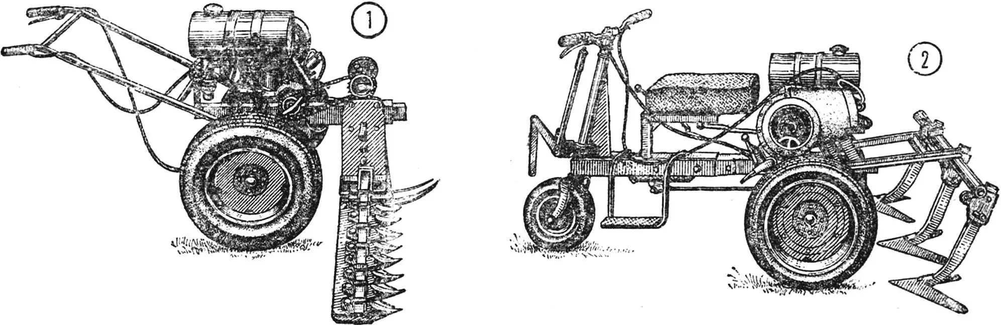
1 — two-wheel version with mower, 2 — three-wheel layout.
The engine was taken from the “Vyatka-Electron” motor scooter. It has a power of 7.5 hp, has a built-in three-speed gearbox and forced air cooling, necessary for power units of compact agricultural machinery, which, as a rule, operate in heavy load and thermal conditions.
The drive wheel axle consists of a reducer with reverse from the “Muravey-TGA” cargo motor scooter and shortened half-axles with universal joints.
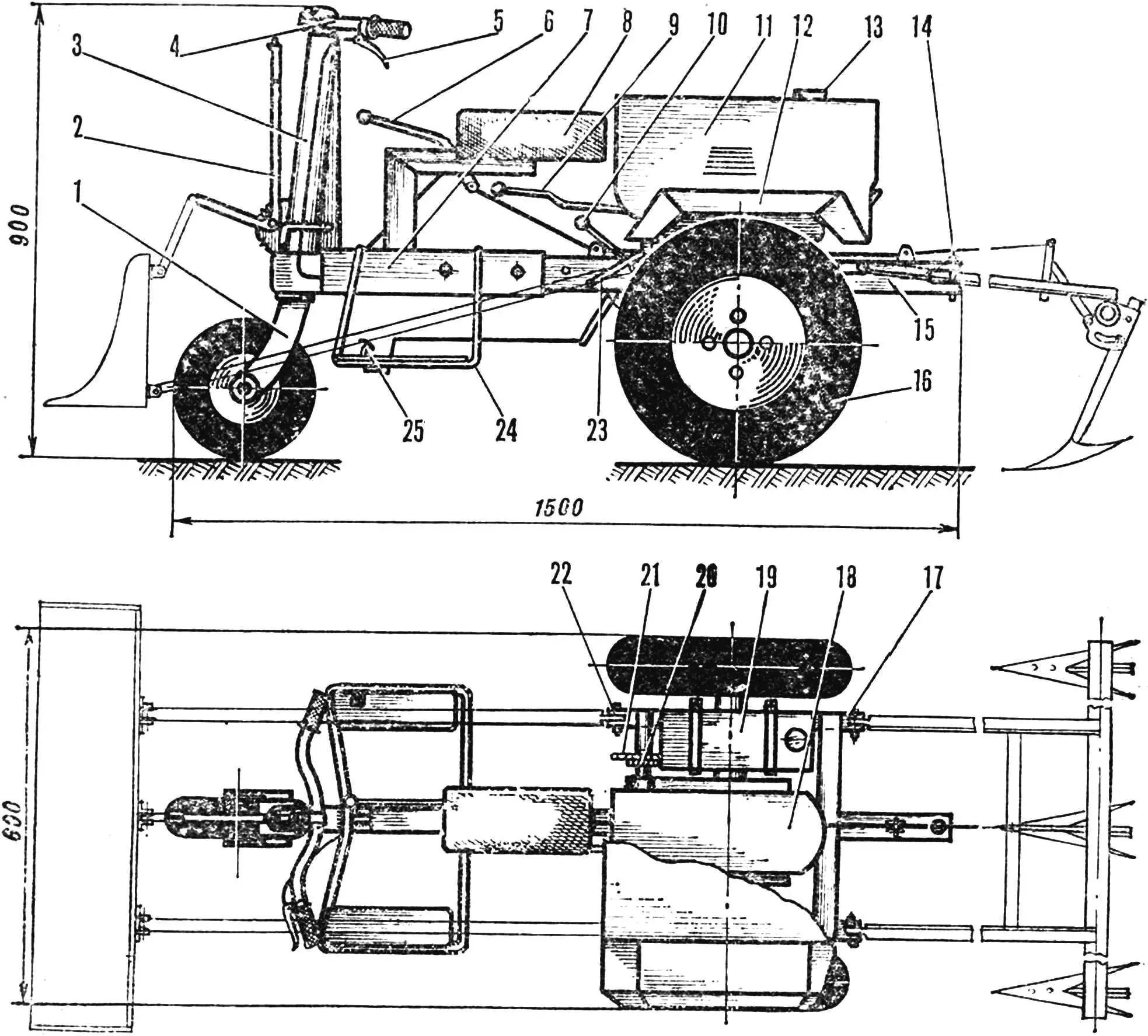
1 — front wheel fork, 2 — front attachment lift lever, 3 — steering column, 4 — steering wheel, 5 — clutch lever. 6 — rear attachment lift lever, 7 — front section frame, 8 — seat, 9 — gear shift lever, 10 — reverse lever, 11 — engine compartment housing, 12 — drive wheel fenders, 13 — fuel tank filler neck, 14 — trailer pin, 15 — walk-behind tractor frame, 16 — drive wheels, 17 — rear frame bracket, 18— engine, 19 — fuel tank, 20 — engine output shaft transmission sprocket, 21 — power take-off shaft drive sprocket, 22 — front frame bracket, 23 — kickstarter, 24 — footrest, 25 — brake pedal.
The drive wheels with hubs and brake mechanisms are from the SZA motorized wheelchair, and the front one is from a kart, with a modified hub. The drum brakes of the drive wheels have a mechanical drive from a pedal installed on the right footrest of the front section. The torque from the engine output sprocket Z1 = 11 is transmitted by a chain with a pitch of 12.7 mm to the drive axle reducer sprocket Z2 = 46, and from its output shafts, through half-axles with universal joints, to the wheel hubs.
The power take-off shaft, which is a separate unit, is driven by another chain drive: from sprocket Z3 = 30, mounted on the engine output shaft next to the transmission one, by a chain with a pitch of 12.7 mm, to the driven sprocket of the shaft Z4 = 8.
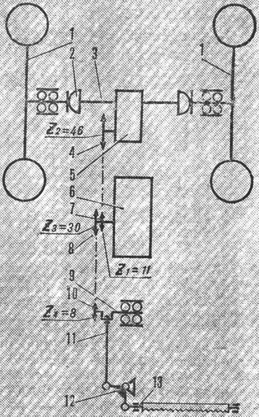
1 — drive wheels, 2 — universal joint, 3 — shortened half-axle, 4 — reducer sprocket (Z2=46, pitch 12.7 mm), 5 — drive axle reducer, 6 — engine with gearbox, 7 — engine output shaft transmission sprocket (Z1 = 11, pitch 12.7 mm), 8 — power take-off shaft drive sprocket (Z3 = 30, pitch 12.7 mm), 9 — power take-off shaft, 10 — shaft sprocket (Z4 = 8, pitch 12.7 mm), 11 — connecting rod, 12 — rocker, 13 — mower moving knife rod.
The frame is welded from steel shaped profiles. It is most convenient to use square and rectangular section tubes. The walk-behind tractor’s backbone beam is made from a tube with a cross-section of 40X25X2.5 mm and a length of 1000 mm. Two side members made of square section steel tube 25X25x2.5 mm are attached symmetrically on both sides of it using transverse tubes. Slots cut at the ends of the side members form brackets for connecting the control handle (in the two-wheel version) or attachments. The central cross member made of a tube of the same cross-section as the backbone beam is welded on top of the longitudinal frame elements. Its end flanges serve as supports for the bearing units of the drive wheel hubs.
For the front section frame backbone beam, a rectangular section tube 45X30X2.5 mm was chosen. Its internal dimensions allow, when assembling the front section with the walk-behind tractor, to freely slide this beam onto the walk-behind tractor beam.
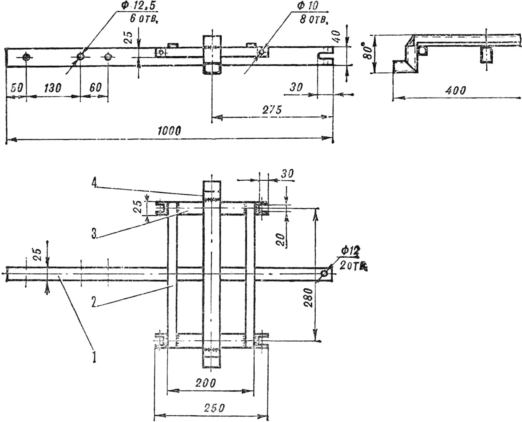
1 — backbone beam, tube 40X25X2,5 mm, 2 — cross member, tube 25X10X2,5 mm (2 pcs.), 3 — side member, tube 25X25X2,5 mm (2 pcs.), 4 — drive wheel support beam, tube 40X25Х2,5 mm.
The steering column housing is formed by a steel tube with an outer Ø 40 mm welded into the front part. Additional rigidity to the connection is provided by a triangular brace made of 8 mm thick steel plate. The steering shaft is made from a Ø 28 mm tube, welded at the bottom to the front wheel fork, bent from an 8 mm thick strip. The upper part of the shaft ends with a clamping collar, where a steering wheel with control levers from the “Voskhod” motorcycle is installed. Bronze bushings serve as bearings for the steering shaft, but ball bearings from a motorcycle steering shaft can also be used.
The seat bracket is welded from 40X40 mm steel angles. Its dimensions are chosen according to the driver’s height. The seat position on the bracket can be adjusted longitudinally. The footrest frame is bent from inch water pipes. Together with steel support platforms, it is welded to the front section backbone beam and serves as a support for the driver’s feet, a bracket for the brake pedal, and protective arches.
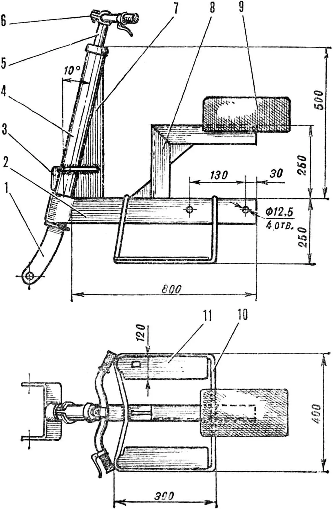
1 — steering wheel fork, 2 — backbone beam, tube 45X30Х2,5 mm, 3 — lift lever bracket, 4 — steering column, 5 — steering shaft, 6 — steering wheel, 7 — brace, 8 mm thick steel plate, 8 — seat bracket, 40X40 mm angle, 9 — seat, 10 — footrest arch, 11 — support platform.
The bracket in the lower part of the steering column housing is intended for mounting a lifting device for front-mounted attachments: a bulldozer blade, forks. A hand brake lever from a GAZ-51 truck handles this task well; its spring latch allows fixing the lever and the tool connected to it in the raised position.
The engine housing is made together with the drive wheel fenders from 0.5 mm thick steel sheet.
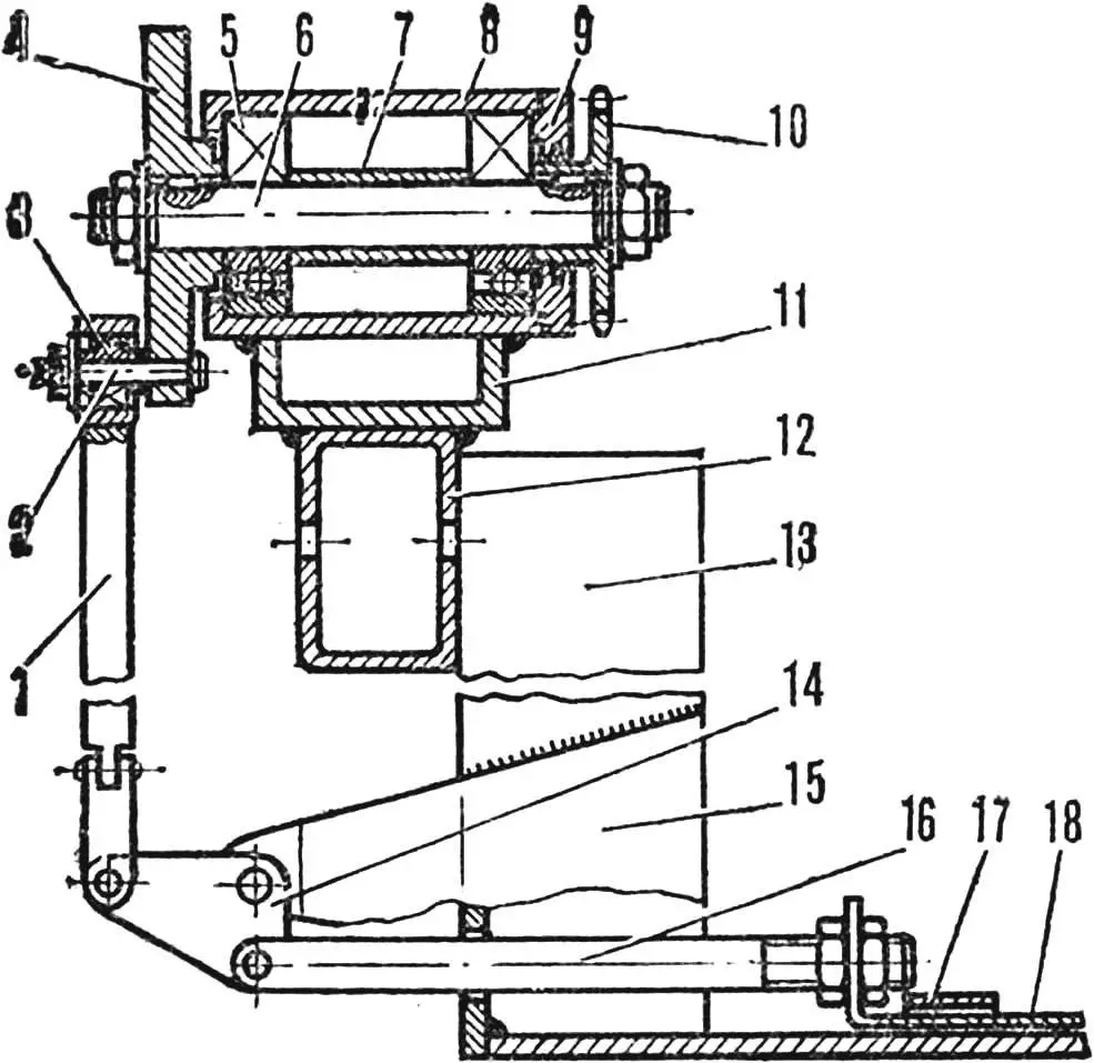
1 — connecting rod, 2 — pin, 3 — spherical bearing, 4 — crank wheel, 5 — bearing No. 60302, 6 — shaft, 7 — spacer bushing, 8 — housing, 9 — cover with felt seal, 10 — sprocket, 11 — spacer, 12 — housing bracket, tube 45X30Х2,5 mm, 13 — stand, 14 — rocker, 15 — bracket, 16 — moving knife rod, 17 — guide, 18 — mower moving knife.
To increase traction with the soil during plowing, deep cultivation, and improve cross-country ability, lugs are fitted to the wheels. The rim is obtained by rolling a 100 mm wide steel strip into a ring and connecting the joint with two bolts. Eight 25Х25 mm angles are welded or riveted to it from the outside. Four of them have a length of 160 mm. By bending the parts protruding beyond the rim width, we get side stops that secure the lug on the wheel.
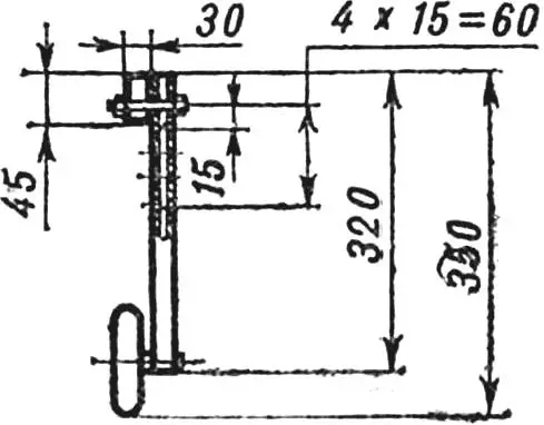
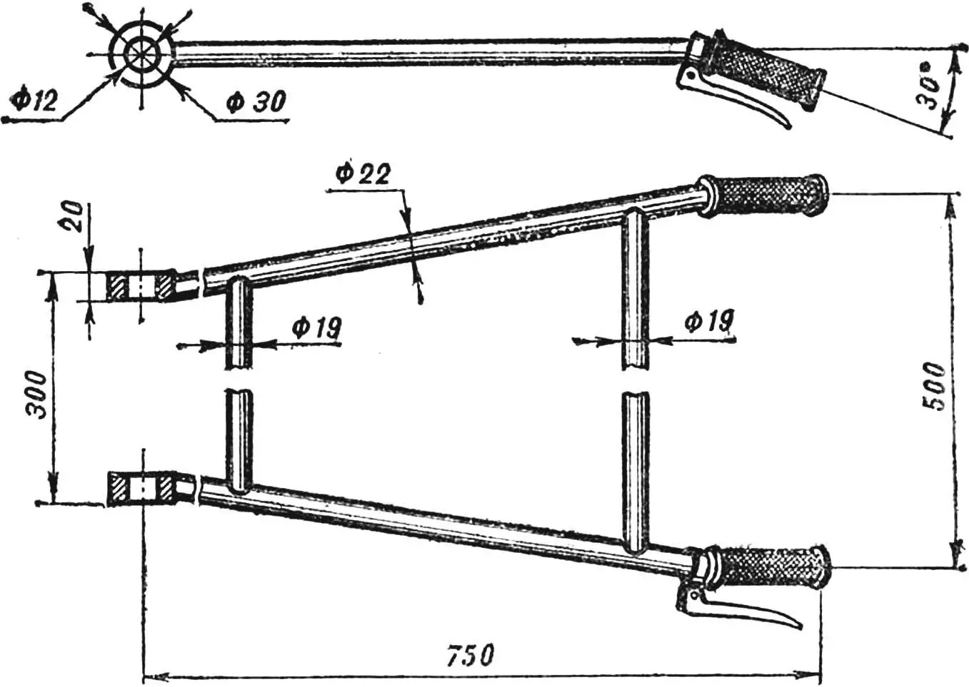
The walk-behind tractor control handles for the two-wheel version are welded from steel tubes with an outer Ø 22 mm. In this case, motorcycle clutch lever and throttle control grip are easily fitted on them. The transverse crossbars are made from tubes of smaller cross-section.
The necessary working tools are made from available materials: steel angles, tubes, rods, sheet metal, and are also assembled using elements from decommissioned agricultural implements: plowshare from a plow, cultivator tines.
For plowing small plots, the walk-behind tractor is equipped with a single-furrow plow — posts made of strong timber with a plowshare.
The cultivator with a working width of about 800 mm has three removable tines. By making several sets with different working edge widths, they are easy to replace — depending on the crop being processed.
The transport cart frame, designed for a load capacity of up to 400 kg, is metal, welded from 50X50 mm angles. Two wheels from a kart are mounted on a common axle. The body is wooden, with a folding rear side.
The bulldozer blade is made from 3—4 mm thick steel sheets. Its width is 700 mm, and although the traction developed by the walk-behind tractor with lugs is quite high, it is mainly intended for snow removal.
Forks for collecting mowed grass into haystacks are made from angles welded into a frame and Ø 10 mm steel rods.
To gather grass into windrows, clear the garden of dry branches, and clean forest clearings, tractor rakes — a drag rake — will help. For their load-bearing cross beam, a Ø 40 mm steel tube can be used, and the teeth can be bent into a semicircle from thick steel wire.
The power take-off shaft for driving mechanized tools is made as a separate removable unit. In its machined steel housing, a shaft is mounted on two bearings No. 302 (better 60302— they have protective washers). A driven sprocket is attached to one end, and a drive flange or crank wheel for the mower connecting rod to the other. The housing is welded to a bracket made from a 45X30X2.5 mm tube section, with which the entire unit is fitted onto the frame backbone beam. The mounting location with a through bolt is adjusted according to the drive chain length.
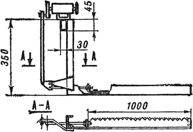
In our machine, the power take-off shaft is used mainly to drive the mower, so both mechanisms are combined into one unit. The mower stand — made from a No. 12 channel section — is bolted to the power take-off shaft bracket. And in its lower part, the mower working organs are installed: a stationary one, and above it, in plate guides, — a moving one. The cutting width is about 1000 mm. The moving knife is driven by a rod from a rocker, the axis of which is fixed on the stand bracket. The conversion of power take-off shaft rotation into reciprocating motion is accomplished by a crank-connecting rod drive.
The mower can be installed on the frame in any machine layout. On three wheels, it’s good to mow an open field, meadow, and by removing the front section and securing a control handle in the rear frame brackets, it’s convenient to work in the garden between trees and on a forest clearing. A small support wheel under the beam will help maintain the cutting height accurately.
The walk-behind tractor design provides for the following attachment mounting options. The front frame brackets are used for connecting the bulldozer blade and forks. The rear ones — in the two-wheel layout — for the control handle, and in the three-wheel layout — for the cultivator, harrow, tractor rakes. The cargo cart is hitched using a pin to the frame backbone beam. And for plowing on a two-wheel walk-behind tractor, the plow is secured with a “stirrup” type clamp directly to the beam, on the side of its longer part with the working edge toward the engine. Since the rear axle has reverse, the walk-behind tractor can work moving in reverse as well.
The control levers for the power unit and attachments are arranged in the front part of the machine next to the driver’s seat. There are levers for controlling the gearbox, axle reverse, and lifting rear-mounted equipment. A brake pedal is mounted on the right footrest, and on the steering wheel — a clutch lever and a carburetor throttle control grip. The engine is started with a kickstarter, the lever of which is removable.
“Modelist-Konstruktor” No. 6’85
Recommend to read
 HOLOCAMERA — ANY
Because of the deterioration of the old Velocimetry often have to fix. The new find does not always succeed there, but another size of industry and trade not able to keep up with... CHAIR FIDGETS
There are restless people, they are literally turning on the seats, even when doing serious work. Why not meet them and not make the chair so that he could turn? The chair...
