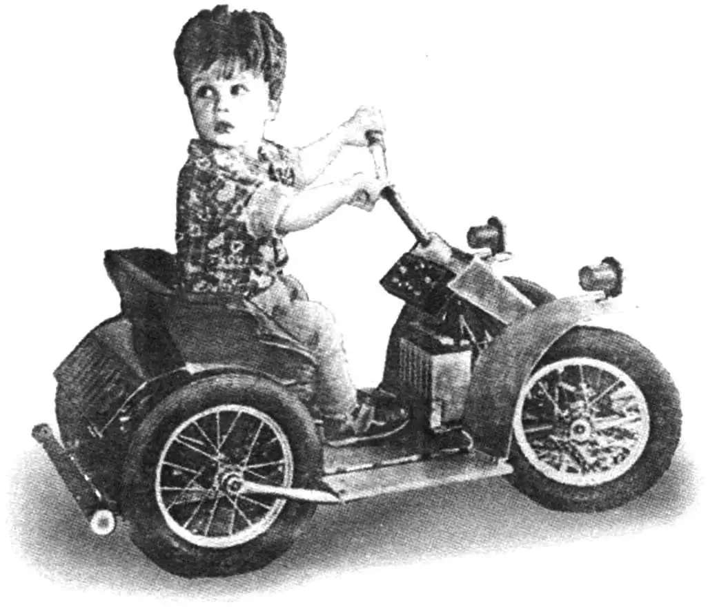
When my grandson Grisha started growing up and stopped paying attention to his previously favorite rattle toys, the family began to notice that he started showing interest in various tools and even mechanisms. Then I decided to make him a small electric car-quad bike that could be ridden outside in good weather, and in bad weather — even in the room. And not only so that the child would enjoy riding — while mastering driving skills, he simultaneously became familiar with technology and learned about its structure.
The basis of the electric car’s construction is a platform made from a solid furniture particle board 16 mm thick. In the front part, two channel-section longitudinal members bent from a 2 mm thick steel strip are attached to the platform. The front axle beam, steering system, and front bumper are mounted on the longitudinal members. A drive consisting of two electric motors, a reduction gearbox, an intermediate shaft, and chain drives with sprockets is installed in the rear part of the platform.
The electric car’s wheels have pneumatic wide-profile tires size 56—205. Two wheels were taken from an old children’s bicycle “Mishka”, and two more (front and rear) were purchased at a store where they were sold as spare parts for such a bicycle. Since the suspension of all wheels is rigid, shock absorption is provided by selecting optimal tire pressure.
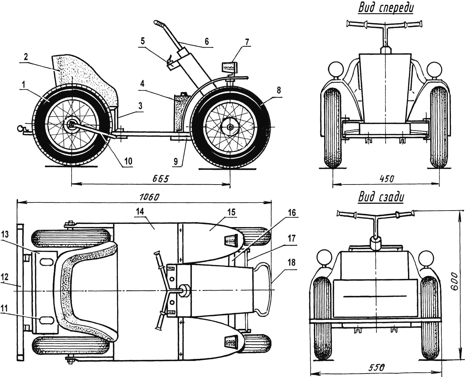
1 — rear wheel (from children’s bicycle, 2 pcs.); 2 — seat (plywood, foam, leatherette); 3 — seat support post (angle 15×15, 2 pcs.); 4 — battery (12 V, 9 A); 5 — steering bracket; 6 — steering wheel; 7 — headlight mockup with white reflector (2 pcs.); 8 — front wheel (from children’s bicycle, 2 pcs.); 9 — longitudinal member (2 pcs.); 10 — rear wheel longitudinal link (1/2″ pipe, 2 pcs.); 11 — white reflector (2 pcs.); 12 — rear bumper; 13 — rear hood (duralumin, sheet s1); 14 — frame-platform; 15 — front fender (duralumin, sheet s1, 2 pcs.); 16 — front beam; 17 — steering link; 18 — front bumper (steel, sheet s2)
The driving wheels are rear. Both have overrunning clutches and sprockets. There is one feature in the design: one wheel (right) provides forward movement, and the other (left) — backward. For this, both wheels are installed with sprockets facing inward. The clutches work in opposite directions. Factory bicycle axles are used. But to reduce the wheel mounting shoulder, the bearing cones are screwed in as far as possible along the thread.
The front wheels are steerable. The steering wheel is bicycle-type. The steering shaft is installed in two plain bearings (nylon bushings), and a steering arm is fixed at its lower end. It is connected by links to the turn knuckle levers, which are hung on brackets that are pivotally connected to the ends of the front beam. Both the beam and knuckles were made without welding, so they are detachable assembly units consisting of several parts. The beam consists of upper and lower cross members connected to each other by studs. The lower cross member is bent from a steel strip in the form of an angle, and a steering shaft support bracket is mounted in its middle. Fender mounting brackets are screwed to the upper cross member, and it itself is a simple plate with a 22×4 mm cross-section.
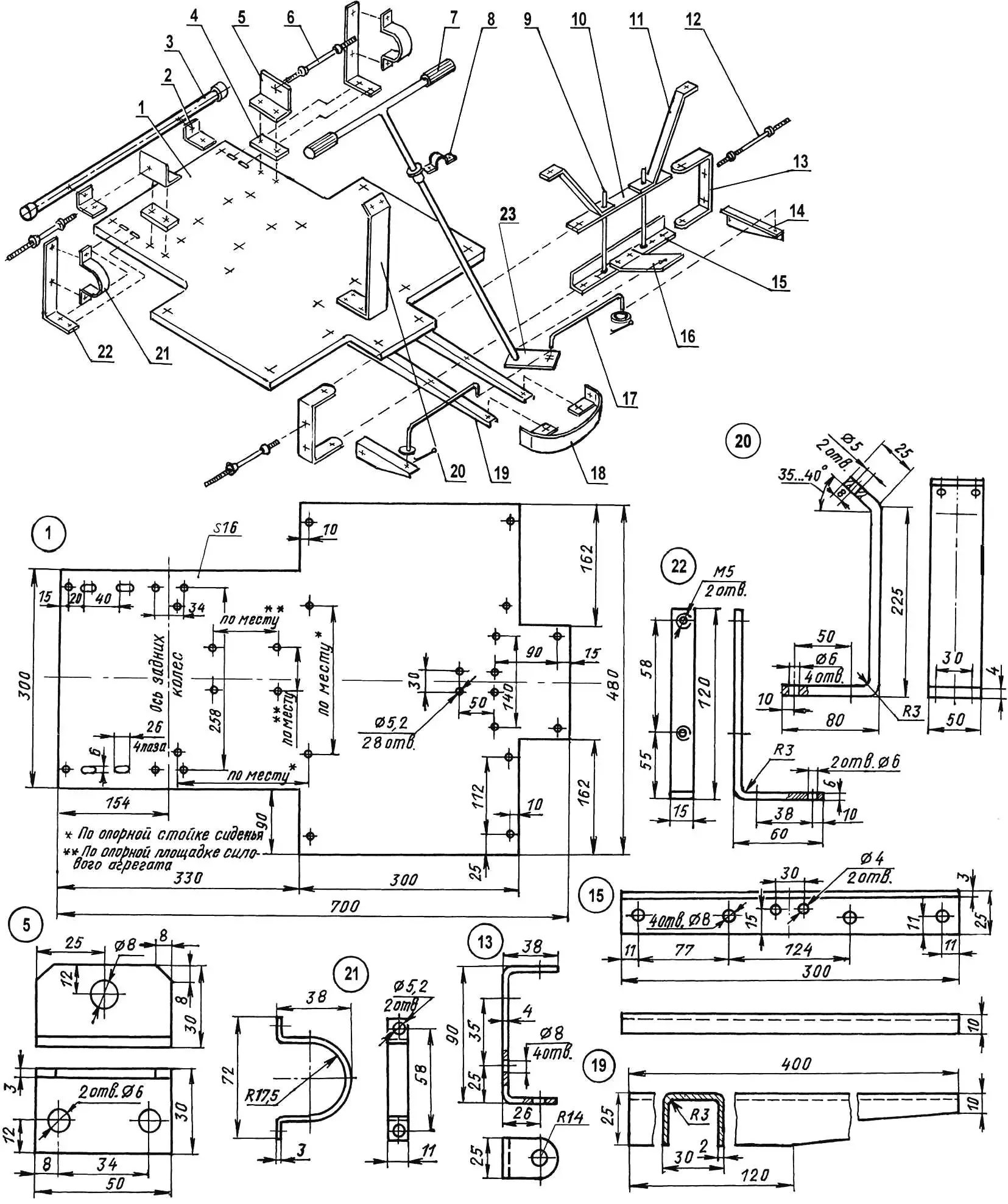
1 — frame-platform (particle board, s16); 2 — rear bumper mounting brackets (angle 30×30, 2 pcs.); 3 — rear bumper (3/4″ pipe); 4 — pad (particle board, s16, 2 pcs.); 5 — axle bracket (angle 30×30, 2 pcs.); 6 — rear wheel axle (from children’s bicycle, 2 pcs.); 7 — steering wheel (from children’s bicycle); 8 — steering wheel mounting bracket (steel, sheet s1); 9 — M10 studs with nuts connecting upper and lower cross members (2 pcs., 8 nuts); 10 — upper cross member (steel strip 25×3); 11 — front fender bracket (steel strip 25×2, 2 pcs.); 12 — front wheel turn knuckle spindle-axle (from children’s bicycle, 2 pcs.); 13 — turn knuckle bracket (steel strip 25×4, 2 pcs.); 14 — turn knuckle lever (angle 30×30, 2 pcs.); 15 — front beam lower cross member (angle 25×10); 16 — steering shaft thrust bracket (steel, sheet s3); 17 — steering link (steel, rod Ø5, 2 pcs.); 18 — front bumper (steel, sheet s2); 19 — longitudinal member (bent channel 30×25, 2 pcs.); 20 — steering shaft bracket (steel, sheet s4); 21 — intermediate shaft bearing mounting bracket (steel strip 11×3, 2 pcs.); 22 — intermediate shaft support bracket (steel, strip 15×6, 2 pcs.); 23 — steering arm (steel, sheet s3)
The turn knuckle base is a bracket. A turn lever and front wheel spindle-axle are attached to it. Between the rubbing surfaces of the steering drive parts, where possible, I placed nylon washers, and I periodically lubricate the other pivot joints with grease. A bumper is attached to the front of the longitudinal members. It is shaped. Limiters for the steering arm travel are also installed here — the wheels turn only 45° in each direction.
The transmission could be quite complex and heavy. But I happened to buy an unusual but suitable gearbox cheaply at a flea market. As the seller told about its origin — this mechanism is from some decommissioned aircraft. This gearbox has several advantages: it’s light (duralumin housing), compact, and most importantly — it had a very large gear ratio — 250. I even had to not use and dismantle the first two stages of the gearbox. I replaced the two shafts of the subsequent gears with extended ones and connected electric motors to them through elastic couplings (very tightly fitted rubber tubes).
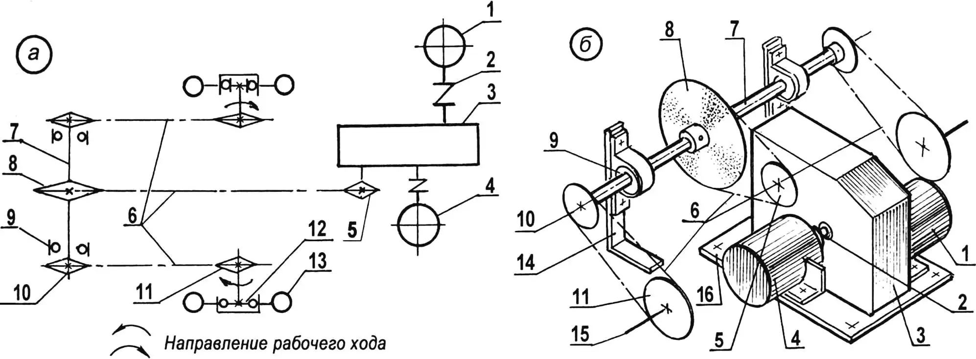
1 — forward drive electric motor (N = 20 W, 3000 rpm, from car windshield wiper); 2 — coupling (rubber tube, 2 pcs.); 3 — gearbox (aircraft); 4 — reverse drive electric motor (N = 8 W, 3000 rpm, from car heater); 5 — output shaft sprocket (z = 10); 6 — drive chains (t = 12.7); 7 — intermediate shaft; 8 — large intermediate shaft sprocket (z = 30); 9 — bearing 202 (2 pcs.); 10 — small intermediate shaft sprocket (z = 8, 2 pcs.); 11 — drive wheel sprocket (z = 16, 2 pcs.); 12 — drive wheel overrunning clutch; 13 — drive wheel (2 pcs.); 14 — intermediate shaft support bracket; 15 — rear wheel axle (2 pcs.); 16 — power unit support platform
I took the electric motors from a passenger car — both 12 V with 3000 rpm. One of them — 8 W power (from heater fan) — I connected to the shaft of the first (after reconstruction) stage with a large gear ratio, the other — 20 W power (from windshield wiper drive) — to the second stage shaft. This more powerful electric motor moves the car forward, and the other, respectively, backward.
I first attached the electric motors to angle brackets, cutting semicircular grooves in their vertical flanges for the motor housings. Then I installed the gearbox and electric motors on a common platform (from particle board), and then fixed this platform to the frame-platform. I performed this operation in place after mounting the intermediate shaft and wheel axles.
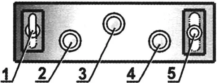
1 — two-position toggle switch for drive and battery charging; 2 — green indicator light for forward drive engagement; 3 — yellow indicator light for braking, stopping and neutral; 4 — red indicator light for reverse drive; 5 — three-position toggle switch for drive engagement (“Forward”, “Backward”) and stop
The electric motors are powered by a 12 V battery. The battery is secured to the platform by the steering column. Its charge lasts approximately 15 minutes of continuous driving. After that, the battery needs to be recharged for approximately the same time using a charger operating from a 220 V network. I monitor the battery’s performance recovery using the device’s ammeter.
In transmission calculations, I limited the electric car’s speed to 5 km/h. After all, during operation it’s necessary for adults to easily keep up with it and control the child’s actions. In the calculation, I even took into account that DC electric motors under load have significant “slip” and instead of 3000 rpm will rotate only at 2000 rpm. However, I still couldn’t do without an intermediate shaft with sprockets and chain drives.
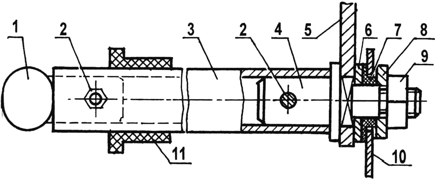
1 — steering wheel; 2 — pin-bolts M4; 3 — steering shaft (1/2″ pipe); 4 — shaft tip (St3); 5 — arm; 6 — upper washer (St3); 7 — thrust bushing-bearing (nylon); 8 — lower washer (St3); 9 — nut M8; 10 — thrust bracket; 11 — upper shaft bushing (nylon)
The sprocket on the gearbox output shaft has 10 teeth, on the intermediate — the large sprocket has 30 teeth, and the small ones — 8 each, and finally, the sprocket on the wheels — 16 teeth each. The total transmission gear ratio is 36. The tooth pitch of all sprockets and chains is the same — 12.7 mm. I didn’t design a special chain tensioning mechanism, but instead made longitudinal slots instead of holes for mounting the intermediate shaft brackets on the platform, along which the brackets can be repositioned and chains tightened. But the latter are of small length and with increased strength margin for such an electric car. Over a year and a half of operation, I never had to tighten the chains. Only when installing the gearbox, intermediate transmission shaft, and wheels, it’s necessary to strictly observe the alignment of the rotation planes of the sprockets of each chain drive. Therefore, I drilled the hole for the pin-bolt in the mounting bushing and intermediate shaft only after precisely aligning the sprockets of the first chain drive stage in one plane. For the other two stages, this can be easily done by shifting the positions of the bearing cones on the axles.
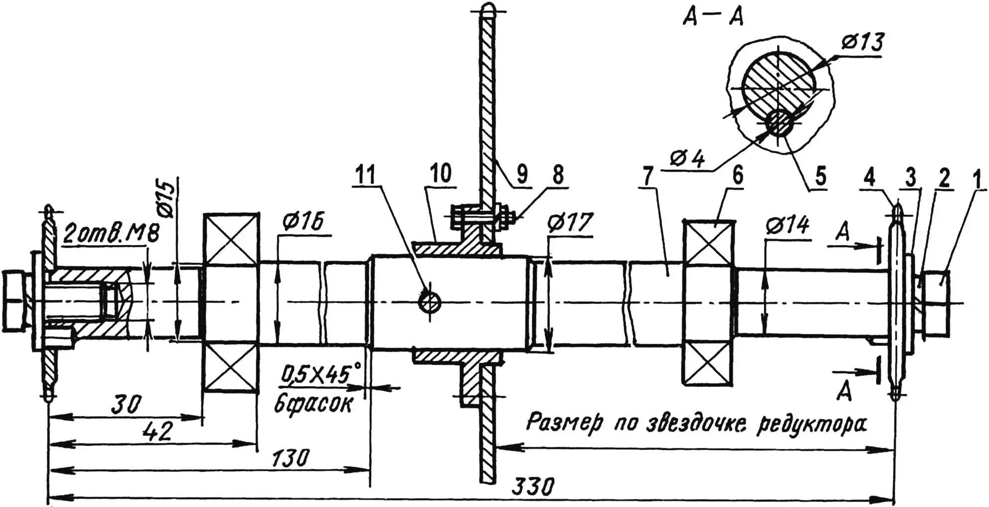
1 — sprocket mounting (screw M8, 2 pcs.); 2 — spring washer (2 pcs.); 3 — washer (2 pcs.); 4 — small sprocket (z = 8, 2 pcs.); 5 — pin; 6 — bearing 202 (2 pcs.); 7 — shaft (steel 45, rod Ø17); 8 — bolt M4 with spring washer (2 pcs.); 9 — large sprocket (z = 30); 10 — mounting bushing (St3); 11 — pin-bolt M4 (hole for bolt is drilled after aligning the planes of the gearbox output shaft sprocket and large intermediate shaft sprocket)
Control of the electric car’s electric power unit is carried out from a control panel located under the steering wheel. For movement, first a two-position toggle switch for drive (acting as an ignition lock) is turned on, and a yellow indicator light lights up on the panel. Then the lever of another (three-position) toggle switch is engaged, for example, position “Forward” (green light lights up) or “Backward” (red light turns on). Braking is automatic: it’s enough to put the three-position toggle switch lever in the neutral position. Of course, the lights don’t play a special functional role, but it’s more interesting to ride the electric car with them.
The seat is armchair-type, homemade. Its base is made of plywood. Foam is laid inside, and the entire seat is upholstered with bright red leatherette. On the frame, the seat is mounted on two U-shaped support posts made of 15×10 mm steel angle. The posts are installed along the machine’s axis in place, after mounting the transmission units. A duralumin sheet housing is attached to the back of the seat back. Together they almost completely cover the drive and transmission mechanisms. For the same purpose, another duralumin sheet is attached to the front legs of the seat support posts, so that the driver-child’s legs cannot reach the mechanisms in any way.
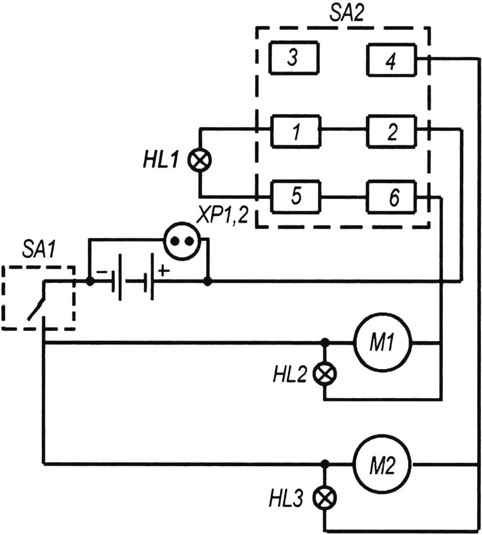
M1 — forward drive electric motor (automotive, from windshield wiper drive); M2 — reverse drive electric motor (automotive, from heater fan); SA1 — two-position toggle switch TP 1—2 for electrical power (ignition lock); SA2 — three-position toggle switch P2T-7 (27 V, 6 A) for forward drive engagement (contacts 6-2), reverse drive (contacts 2—4), neutral (contacts 5-1); HL1 — yellow indicator light for neutral engagement; HL2 — green indicator light for forward drive engagement; HL3 — red indicator light for reverse drive engagement; XP1,2 — charger connection plug half-coupling
The design’s drawback is that there are two electric motors in the drive. When moving, one of them works, and the other rotates idly. It would be better to have one reversible motor.
All the electric car’s body parts were painted light green so the machine would be attractive.
A. MANGUSH
Recommend to read
 CLEARS THE GROOVE…
If after working with quick-drying putty or mastic trowel is not immediately clear, next time will have to work hard in removing the blades with the dried up crust. Convenient and quick... ARMOR SUCCUMB TO “STORM”
The first domestic anti-tank missile system (ATGM) was "bumblebee", developed in Kolomna SKB engineering under the guidance of S. P. Invincible. However, quite a large mass and a decent...
