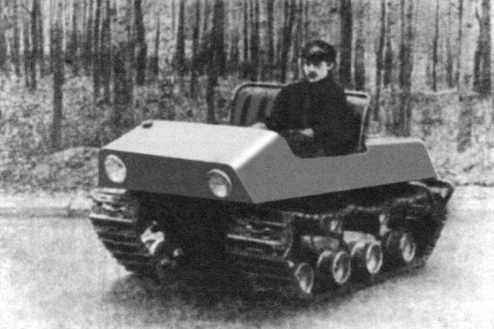
In our laboratory the design of compact machines built a small, but “working” machine – microbeaded for the Forester (see photo). It combines the advantages of large tracked vehicles with high maneuverability and flexibility, the ability to have insulated the cab, the required power and movement speed with a small size and weight.
All this makes the vehicle suitable for use by forestry workers in difficult areas of our country.
Design description
Frame (Fig. 2) a closed rectangular shape consists of two longitudinal spars of the pipe diameter of 42 mm, which bottom are welded four body torsion bar suspension front axle motorized SZA and pipes with a diameter of 22 and a diameter of 27 mm, repeating the silhouette of the body.
The body is made from steel sheet of thickness 0.5 – 0.8 mm. For simplicity and ease of manufacture were first cut out of cardboard templates. Then it was done of the workpiece, which was fixed Elektro or gas welding to the pipes of the body frame.
The front of the frame is fitted with mechanisms for tensioning caterpillars (Fig. 1, B – B).
In front of the body under the hood is the gas tank. The fuel is delivered to the carburettors by gravity. Instrument panel – car UAZ-452. It has an ignition index of level of gasoline in the tank, the engine temperature gauge, warning light turns.
Fig. 1. Tracked all-terrain vehicle:
1 – stretch ice skating rink; 2 – fuel tank; 3 – a windscreen; 4 – instrument panel; 5 – the gas pedal; 6 – brake lever; 7 – a gear shift knob; 8 – lever kick-starter; 9 – seat; 10 – upper support roll; 11 – casing of a band brake; 12 – bracket axles; 13 – sprocket; 14 – the carburettor; 15 – pump; 16 – casing of the fan; 17 – axis; 18 – differential; 19 – engine M-62; 20 – output shaft; 21 – the axle shaft; 22 – intermediate shaft; 23 – pull brakes; 24 – sprocket of the engine; 25 – a gear shift; 26 – thrust kick-starter; 27 – blinds; 28 – battery; 29 – fan (cover removed); 30 tracks; 31 – damper; 32 – support roller; 33 – sleeve; 34 – the case of torsion; 35 a frame; a 36 – lever torsion bar; 37 – a bolt; 38 – axis of the rink; 39 – bearing No. 302; 40 – the worm for tensioning caterpillars; 41 – worm wheel; 42 – key; 43 – bearing No. 303; 44 – a guide tape; 45 – circuit; 46 – grouser
Windshield: organic glass secured in a tubular frame sealing rubber.
In the winter and in bad weather provides for the installation of cockpit canvas, which is stretched on a removable frame made of duralumin tubes with a diameter of 18 mm. cabin Heating of the driver is made from the muffler that attaches to the exhaust pipe of the engine by means of flanges. In winter it is placed under the driver’s feet, and in the summer, thanks to flange mount, rotated in the opposite direction and placed under the right track. Additional heating gives warm air from the fan forced motor cooling.
Engine – upgraded M-62 Ural. Located in the rear of the body. Alteration him under forced air cooling is as follows: the engine front cover is removed the shaft (Fig. 3, POS. 13), which is welded by electric welding to the small gear, naturally. To the engine front cover argon-arc welding is welded to the bearing housing No. 204, which is the second pillar of the drive shaft of the fans. In the absence of argon-arc welding the bearing housing can be mounted with M6 bolts through the gasket to avoid oil leakage from the crankcase. The shaft of the fan drive with a small gear valve timing is fixed on the engine crankshaft dowel and the bolt M8.
On the drive shaft is mounted with double-strand pulley (Fig. 3, POS. 6), which by means of V-belts transmits the rotation of two driven pulley. They vasilopeta mounted axial fans. The pulleys are located directly in front of the engine cylinders and mounted on brackets that are welded to the body frame.
The air flow is directed to the cylinders with covers (Fig. 1, POS. 16, the casing of another fan not shown). After cooling, the cylinder a stream of air is discharged to the outside through the blinds of the bottom of the engine compartment, which is located in the direction of motion of the vehicle. In winter, the louvers are closed the bottom and the air enters the passenger compartment. The air intake for engine cooling is through louvers in the top cover of the engine compartment.
The engine is started manually with a lever located on the left side of the driver seat. The lever rod is connected with a short pedal kick-starter.
Fig. 2. Frame and frame of the vehicle
Fig. 4. Diagram of main transmission:
1 – the bearing № 205; 2 – screw M14; 3 – outer axle bearing; 4 – sprocket; 5 – bolt M10; 6,7 – key; 8 – the hub of the brake pulley; 9,10 – bolts M10; 11 – the lever of a band brake; 12 – bearing shell; 13 – differential (SZA); 14 – differential shaft; 15 – sprocket shaft of the differential; 16 – bearing No. 205; 17 – axis; 18 – bearing number 206; 19 – bearing; 20 – frame; 21 – the band brake; 22 – brake pulley; 23 – sprocket
Fig. 5. Diagram of a caterpillar:
1 – belt; 2 – chain; 3 – guide; 4 – grouser; 5,6 – rivet
The Rover applies the chain transmission from the engine to the differential. This is caused by the structural arrangement of the engine on the frame of the vehicle and using the differential from the sidecar, SZA, adapted to the transmission chain.
Modification of the engine M-62 Ural under chain transmission transmission output shaft is as follows: removed fork cardan and protecive seat sprocket (from the motorcycle IZH-56), having a step of 15.88 mm and number of teeth – 18. The sprocket is welded to the fork of the cardan shaft by electric welding.
During the test, the Rover has identified the need to supply an intermediate chain reduction gear with a ratio of 3. It is possible to reduce the maximum speed to 50 km/h and increase traction on the tracks. Rotation from the gearbox to the differential reported chain. Thus, the torque is transmitted from the engine to the gearbox, then the differential shaft (Fig. 4), and on to the axle shaft. They are mounted on the two sprockets, having a step 37 mm and the number of teeth 26 (Fig. 4, POS. 4, 23). Sprockets drive the tracks. As the axle shaft substantially extends beyond the supports on the frame and can bend under load, the outer end it is equipped with additional support in the form of a bracket fixed to the frame body.
A Rover four speed forward and the same back. Changeover and reversal of all-terrain vehicle produced a single lever taken from the UAZ-452.
The rotation of the vehicle is accomplished by braking one of the two axle shafts of the differential. When a caterpillar is slowed down, the other starts moving with double speed, as if looking ahead: the Rover turns.
For braking of the axle shafts of the differential band brake is used (Fig. 4, POS. 21), which consists of a brake disk bolted to the hub of the M10 sitting on the axle shaft, and a metal strip width of 38 mm. thereto a copper or aluminum rivets to fasten the friction lining sizes 40x70x6 mm. When operating the band brake should cover approximately three-quarters of its pulley. One end of the ribbon is attached to the bracket that is welded to the frame, and the other is pivotally connected to the lever (Fig. 4, POS. 11) band brake located in the cabin of the driver.
The Rover uses two of the control pedals: accelerator and clutch. The brake pedal is missing, as is sufficient to pull both levers, pre-squeeze the clutch, like caterpillars inhibited, and the vehicle stops.
Caterpillar – rubber-metal, with two parallel chains with a pitch of 37 mm (Fig. 5) from the conveyor machinery. Available on a chain tabs are processed in the form of lugs from a steel angle 20x20x3. Them rivets with a diameter of 6 mm mounted rubber condolence from the conveyor to a thickness of 7 mm.
Fig. 3. The device of air cooling of the engine:
1 – a cranked shaft; 2 – spacer; 3 – front cover of the engine; 4 – bearing housing: 5 – klingeman; 6 – double-pulley; 7 – spacer sleeve; 8 – a nut of fastening of a pulley; 9 – bolt M8: 10 – key; 11 – bearing No. 204; 12 – small gear valve timing; 13 – shaft fan drive: 14 – pulley; 15 – the bearing № 202; 16 – bearing No. 204; 17 – vasilopeta fan; 18 – frame: 19 – bolt M10
To the direction of movement of rollers used rubber protrusions (Fig. 5, POS. 3) from the belt (profile “E” GOST 1284-57), which are attached to the belt by rivets 8 mm diameter, passing through the grouser and welded to its outer side.
During the design of the caterpillar must be considered that the middle of the thickness of the rubber tape should lie exactly on the line connecting the centers of the rivets of chains. Otherwise, the tape is experiencing deformation, working in tension or in compression, which leads to its premature wear.
Hardened chains, high-quality welding, durable condolence create easy and reliable caterpillar, and its sufficient width determines the specific ground pressure at full load in the range of 70 g/cm2 . Rover is good on loose snow, dirt, dry soil and asphalt almost silently, without the usual clanging of the tracks.
A. NALIMOV, E. STEPANENKO
Recommend to read NOT BLADE CUTTER Previously, bundles of thin wires hams linked thread — it took a lot of time, and the appearance of the ligament left much to be desired. Now increasingly use a soft plastic tube: missed... WATER IS HEATENED BY SMOKE Having a stove (wood or coal-fired) makes it quite possible to supply hot water to the kitchen sink and even a shower using a water heater — a device that utilizes the heat of hot flue...
Scroll back to top

 Agile, compact vehicle is vital, especially in the snowy and wooded areas. In some countries, for example, in the US, Canada, Japan, this problem is solved by the small-scale production of cars type motoart. Our industry has also begun to issue such equipment: there motonarty “Buran”, Amurets and others. However, these machines are more for entertainment, they have not even insulated the cab.