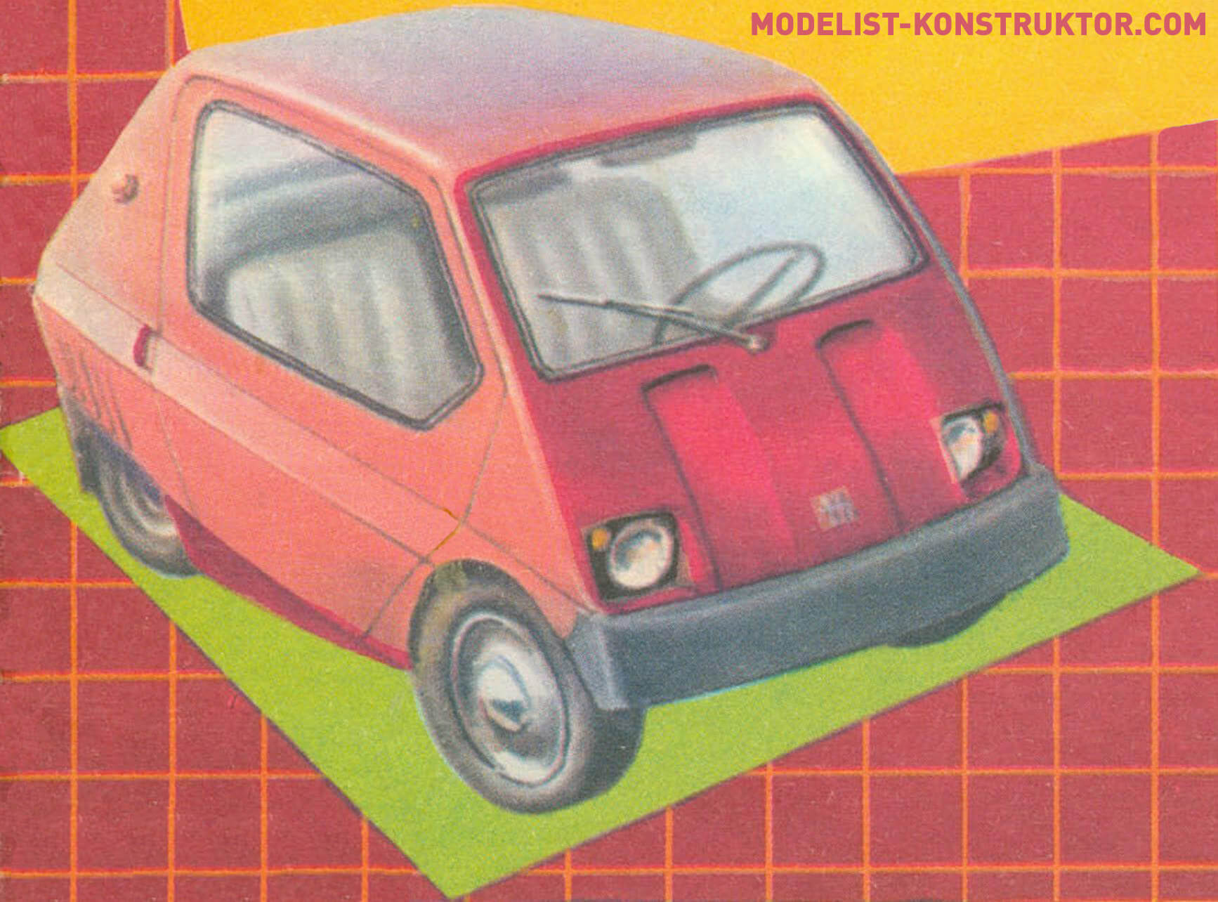
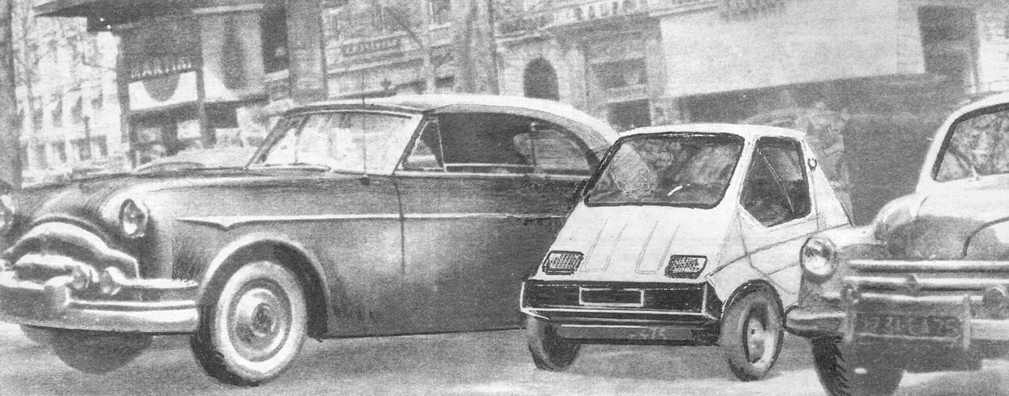
If Attesi-TX was able to charm you in the same way as it did me in its time, then I think I can quite help you make this very simple, compact and ultimately cheap and affordable car.
“Attesi-TX” is a two-seater, two-door car with a T-200M type engine with a displacement of 200 cm 3 and a power of about 14 hp. With. The car has four wheels, but the rear wheels are closer together and their track is much narrower than that of the front ones. This is done so that you can get rid of the differential, the use of which significantly increases the cost and weight of the car.
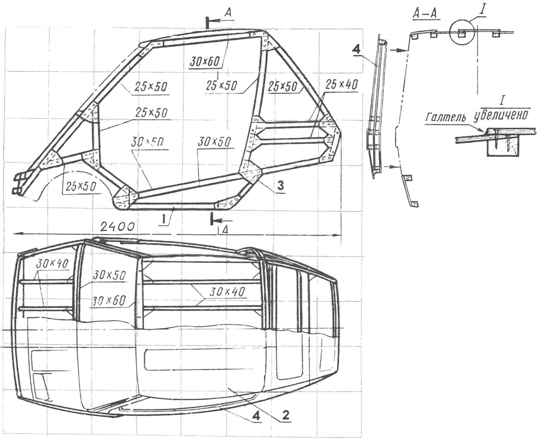
Microcar – frame design; its frame is a spatial truss made of tubular elements, and the body is a frame structure covered with plywood, covered with a layer of fiberglass with epoxy glue.
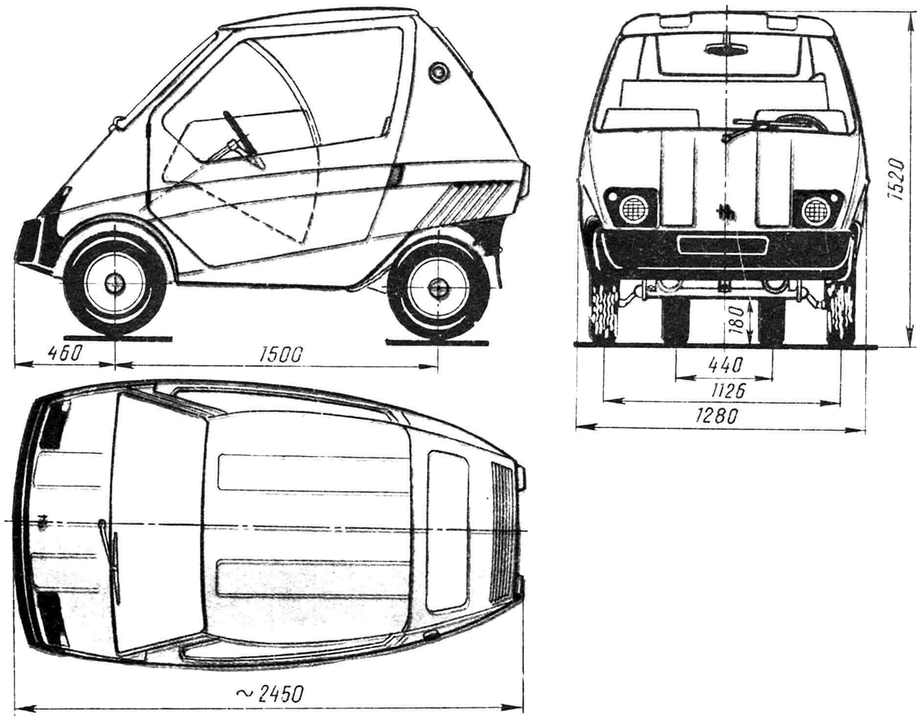
The engine of the machine is located at the rear and transmits torque to the drive wheels using a two-stage chain transmission. The front axle of the car is from an S3D (or S3A) sidecar, the rear axle is homemade, on trailing arms and shock absorbers from a medium (or heavy) motorcycle.
If your future car turns out to be close in ideology to Attesi-TX, then you will need the following: for the frame – seamless steel pipes Ø 40X2.5 mm, Ø 36X2.5 mm, Ø 30X2.5 mm, Ø 22X2.5 mm , as well as sheet steel with a thickness of 2.5 mm, 4 mm and 5 mm; rectangular pipes 36Х60Х3 mm; wooden slats with sections 30X30 mm, 25X50 mm, 25X40 mm, 30X50 mm, 30X60 mm; plywood or hardboard 3…5 mm thick, fiberglass.
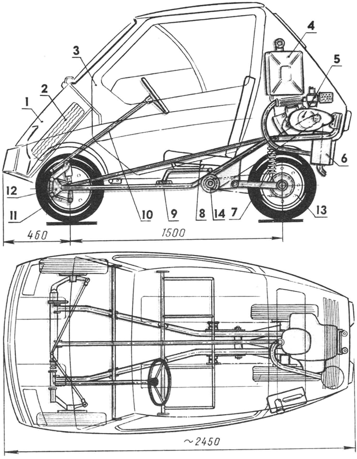
1 – car body, 2 – spare wheel, 3 – door, 4 – fuel tank, 5 – T200-M type engine with a displacement of 200 cm3, 6 – muffler, 7 – rear suspension shock absorber, 8 – seat, 9 – car frame, 10 — steering mechanism (from the S3D motorized stroller), 11 — front wheel, 12 — front axle (from the S3D motorized stroller), 13 — rear wheel, 14 — block of intermediate sprockets.
The windshield is best used from the rear door of a VAZ-2108 or VAZ-2109 car: their configuration fits well into the dimensions of the Attesi-TX. Well, the back and sides can be cut out of organic glass with a thickness of 3…4 mm. When treated with care and regularly treated with car cosmetics, organic glass remains transparent for a long time.
Of the ready-made components and assemblies, you will need the following: a T-200M type engine (from a Tulitsa motor scooter or a TG-200 Ant cargo scooter), a front axle from a motorized stroller. steering rack and pinion mechanism with a steering wheel from a S3D motorized stroller. a pair of wheels from a motorized stroller (for the front axle) and a pair of wheels from a motorized scooter with tires from a motorized stroller (for the rear axle); two shock absorbers for suspension of the rear axle (from Dnepr, Ural or IZh motorcycles); an aluminum 10-liter canister for a fuel tank… And, of course, a hundred other little things that you will probably need in the process of making a car and which are almost impossible to mention in a magazine publication.
FIRST OF ALL YOU NEED TO PREPARE THE PLAZA. To do this, you need to glue several sheets of thick drawing paper and stretch the paper panel onto a shield made from sheets of plywood. I strongly recommend preparing silhouettes of finished parts, assemblies and assemblies, accurately drawn on thick paper or cardboard, as well as the articulated silhouette of the driver – when drawing the frame, this will speed up the design process.
Start drawing the plaza from the front axle. Automotive design traditions require aligning the front axle of the car with the point of intersection of the grid lines, considering it a reference point. Let us accept this as a rule.
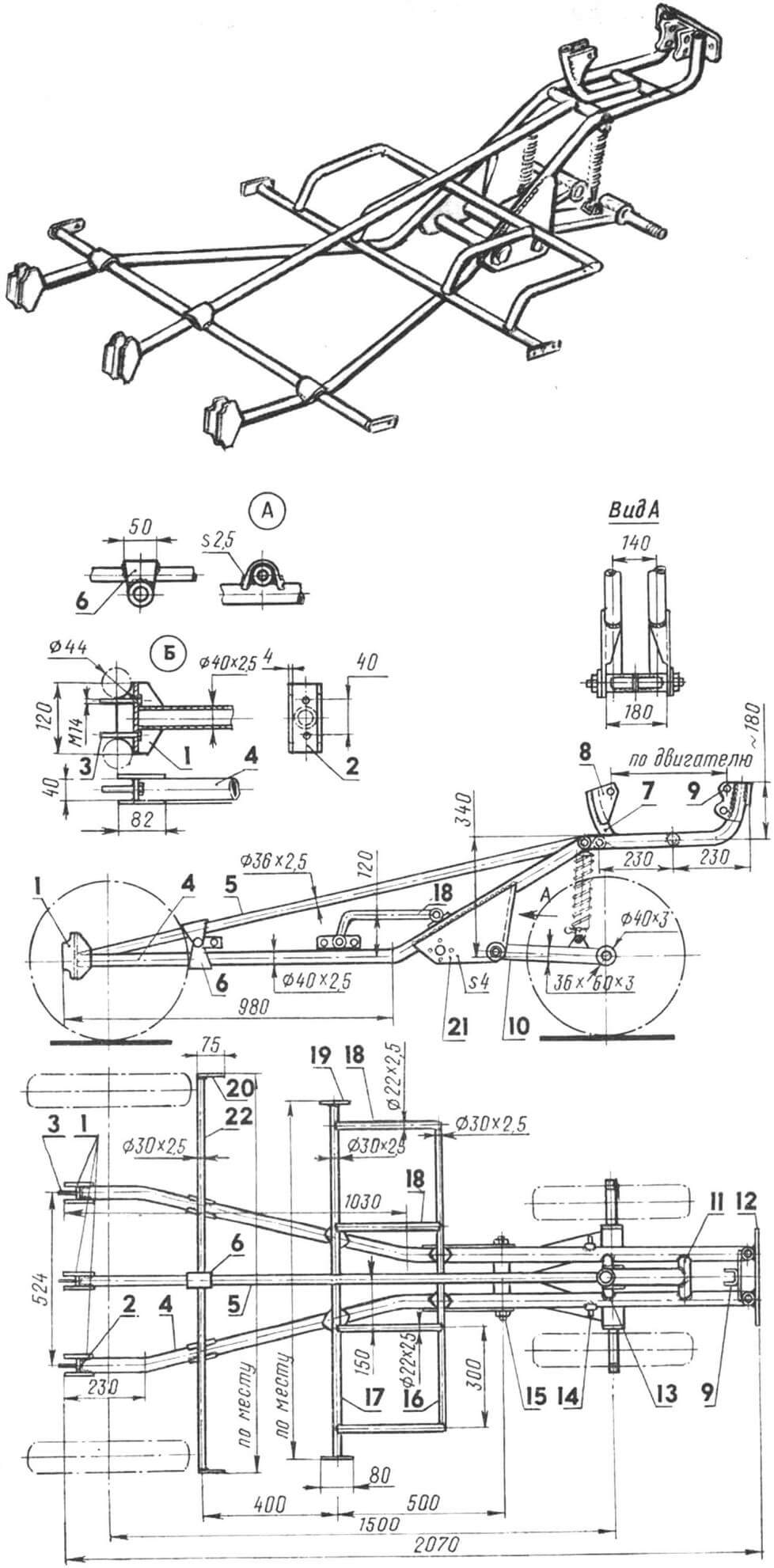
1 — cheek piece connecting the frame and the front axle, 2 — cross member of the connecting point, 3 — M14 bolts (welded to the cross member), 4 — side spar, 5 — central spar, 6 — fitting of the docking point, 7 — front pipe of the engine frame, 8 — engine mounting cheek, 9 — rear engine mounting bracket, 10 — rear wheel suspension arm, 11, 13 — sub-frame cross members, 12 — rear body mounting bracket on the frame, 14 — upper suspension shock absorber mounting bracket, 15 — suspension arm axis rear wheel, 16, 17 — cross members, 18 — seat supports, 19 — middle body mounting bracket on the frame, 20 — front body mounting bracket on the frame, 21 — cheek box of the intermediate sprocket block and rear wheel arm suspension hinge, 22 — front cross member . A – strengthening of the connecting points using forgings, B – design of the connecting point of the frame and the front axle.
I advise you to draw out both the plaza of the frame and the plaza of the body on one plastic sheet – after working with a pencil, the finishing stroke is done with a ballpoint pen of a different color (for example, if the coordinate grid is red, then the frame can be outlined in black, and the contours of the body with a green ballpoint pen).
When drawing questionable places, I recommend using simple cardboard models: they will help you feel the shape of the car, understand the location and contours of individual skin sheets, clarify their cutting,
FRAME MANUFACTURE. In accordance with the drawn plaza, you need to make a simple slipway. To do this, draw a plane of symmetry of the machine on a flat floor; relative to it, we will mark the axes of the side members, the axes of the intermediate shaft and suspension arms, the axes of the front and rear wheels, as well as the axis of the engine sprocket. Next, again in accordance with the space on the floor, wooden spacers and brackets are fixed, onto which the frame spars and cross members can be secured using simple clamps.
Having prepared the frame elements and mutually adjusted them in accordance with the drawing and plaza, secure them on the slipway using clamps and soft knitting wire, tightening the blanks using the so-called “telegraph bandage” method. Check the basic dimensions of the frame, make the necessary adjustments, and you can start welding. It is carried out in three stages: first, the parts are only tacked together, then careful control of the symmetry of the frame, its main dimensions follows, and only after that is the final welding of all seams.
The greatest attention should be paid to the installation of the box, which will house the block of intermediate sprockets and the axis of the rear suspension arm. First, the right and left cheeks of the box are carefully adjusted to the frame; all the necessary holes are drilled in both of them (this can be done together by connecting the cheeks of the box with technological screws with M5 threads); The bearing housings, the intermediate sprocket shaft, and the swing axis of the rear suspension arms are secured. Next, the box is secured to the frame using clamps or M5 technological screws. The main thing that needs to be maintained is the perpendicularity of the axis of the intermediate sprockets and the axis of the suspension arms to the plane of symmetry of the frame. Well, then – a three-stage (tack – control – welding) fixation of the box on the frame.
Now – welding the front axle mounting units. These units are assembled separately, after which they are fixed to the cross members of the front axle and, using the already mentioned “telegraph bandage” and technological screws, are fixed to the frame side members. After checking the perpendicularity of the front axle cross members in relation to the axis of symmetry of the machine, three-stage welding follows.
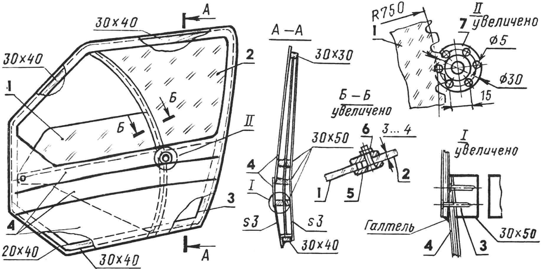
1 – window glass (organic glass 3…4 mm thick), 2 – glazing (organic glass 3…4 mm thick), 3 – frame elements. 4 — outer casing (3 mm thick plywood), 5 — guide (3 mm thick duralumin), 6 — M3 screw with nut, 7 — window drive.
The motor frame is mounted as follows. To begin with, in accordance with the true dimensions of the engine, the front and rear assemblies for attaching it to the frame are made and fixed to the engine with standard mounting bolts and nuts. Next, the engine is installed on the frame, and the fastening units are adjusted to the cross members of the sub-engine frame and the body mounting bracket on the frame. The longitudinal axis of the engine must strictly coincide with the plane of symmetry of the machine. And finally, the already mentioned three-stage welding.
The rear wheel suspension arms are welded from two bushings and a rectangular steel pipe. Inserts made of bronze, nylon or fluoroplastic are pressed into the front bushing of the lever – under the swing axis of the lever; and the axle shafts of the rear wheels are inserted into the rear and secured with so-called “electric rivets”. On each of the levers, a U-shaped bracket curved from a steel strip 3 mm thick is welded to fix the suspension shock absorber. The upper ear of the shock absorber is screwed to the frame – for this, two bolts are welded on it (their diameter must correspond to the diameter of the ear of the shock absorber used).
BODY MANUFACTURING. I suggest you make a body that is simple in design and fairly simple in technology. It consists of a wooden frame and plywood (you can also use hardboard) sheathing. However, this technology is good if you are making just one car. If you manage to find two or three like-minded people, then it is better to use another method of manufacturing the body shell – gluing from fiberglass and epoxy resin onto a block or in matrices. However, today we will not dwell on “serial” technologies, but will talk about purely individual ones. It is best to begin body installation by assembling the side panels. To do this, it is also a good idea to make a simple slipway – draw a side projection on a flat floor and attach wooden brackets to it, on which, using wooden plates, nails or screws, you can temporarily fix the frame slats for mutual fitting and joining. The connection of the frame elements is made using plywood gussets, cut into the slats flush with their surface.
At the same time as assembling the panels, it is convenient to assemble the doors – in this case, their shape will precisely fit into the surface of the body. Please note that the frame of each door is assembled from wooden blocks with half-timber or tenon joints. When lining the body and doors, the latter should be temporarily secured in the frame with screws. It is necessary to lay a strip of plastic film in the gaps between the door and the doorway – this will prevent the door from sticking to the side panel of the body.
Having made the frames of the side panels, secure them to a flat floor and connect them with crossbars. Final gluing of them and the side frames is necessary only after careful verification of the symmetry of the body frame and its main dimensions.
After installing all the crossbars, the longitudinal elements of the roof and front panel – stringers – are secured. All connections are also made using epoxy glue, plywood gussets and screws.
After the glue has polymerized, the frame is processed using a plane, rasp and chisels so that all slats form a smooth, wrap-around surface.
To cover the frame with plywood, a method is used that allows you to obtain surfaces close to double-curvature surfaces. This is achieved by simulating stampings by placing plywood strips on top of each other, followed by puttying the joint so that a kind of fillet is obtained. Having completed the cladding using sandpaper glued to a strip of five-millimeter plywood, treat the surface of the body so that the raised areas of the body become slightly convex in cross-section – this requires sanding down approximately one layer of four-millimeter plywood. After sanding, the frame is leveled with epoxy putty, sanded again and covered with a layer of fiberglass over epoxy resin.
The doors are glazed using organic glass. The door window has two zones: a fixed glass and a lowering window, which rotates approximately 30°, thereby forming an opening sufficient to ventilate the interior.
The manufacture of the body is completed by coating the inside in two or three layers with parquet varnish or diluted (acetone or solvent) epoxy glue. If you want to make the interior quite comfortable, fill the gaps between the frame slats with strips of construction or packaging foam, then cover the interior with artificial leather, and the engine compartment with laminated plastic or hardboard. Between the passenger compartment and the engine compartment there is a partition made of hardboard (lining) and foam plastic (filling).
Install the body on the frame, and in accordance with the location of the docking nodes, attach 3 mm thick sheet steel pads to them with screws and epoxy glue.
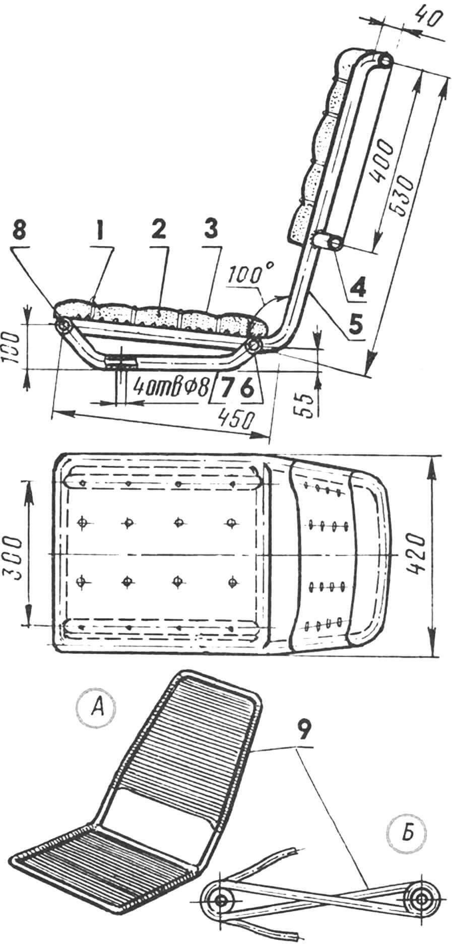
1 – decorative button, 2 – foam cushion, 3 – artificial leather, 4 – upper crossbar (steel pipe Ø 22 X 2 mm), 5 – base of the chair (steel pipe Ø 22X 2 mm), 6, 8 – lower crossbars (steel pipe Ø 22X2 mm), 7 – support bracket (steel pipe Ø 22 X 2 mm), 9 – PVC tube or cord Ø 6 mm. A – frame covered with a PVC cord or tube, B – method of sealing the cord or tube.
The driver and passenger seats are of lightweight construction, each consisting of a frame welded from steel pipes Ø 22X2 mm, covered with PVC cord or tube; foam rubber and covering made of artificial leather or some kind of drapery fabric are fixed on top of the covering.
Each chair is secured to the frame with four M8 threaded bolts with nuts and washers. If it becomes necessary to adjust the position of the chair, drill two or three more groups of holes in the support elements on the frame.
The floor in the cabin is made of 8 mm thick plywood; it is attached to the frame in such a way that when the body is dismantled, it remains on the frame. The polish is covered three to four times with hot drying oil and a couple of layers of red lead.
The fuel tank is made from a ten-liter aluminum canister; it is fixed in the engine compartment on the side wall of the body. The tank is equipped with a fuel tap with a sump from any motorcycle and an extended filler neck. Access to the engine is through the hood in the rear panel of the body. The power plant of the car has a homemade exhaust tract, consisting of an exhaust pipe and a muffler. The latter is made from a cylindrical steel vessel of suitable dimensions; A divider is welded into it – a curved tube with holes drilled throughout its cylindrical part with a diameter of 3 mm. The muffler cavity is filled with drain shavings (preferably stainless steel).
The engine is controlled using cables in a Bowden sheath on the pedals (gas and clutch) and a rigid rod on the lever (gearbox control).
The main brake wheels are the rear ones – their brake pads are driven from the pedal using a rigid rod connected to the rocker arm of the equalizing mechanism; Then the arms of the rocker arm are connected with the help of cables to the brake pad drive lever. The front wheels of the car are also braked – using the standard hydraulic drive of the S3D motorized stroller. The brake master cylinder is controlled by a lever with a lock; thus, the front brake can be used as both a parking brake and an emergency brake in addition to the rear brake.
The electrical equipment of the vehicle is made according to the design of the Ant cargo scooter. The instrument unit is also used from it – a speedometer with an ignition switch and warning lamps.
That’s all, actually. True, this is only the end of the article, and the end of the work is still very, very far away. You still have to paint the body and trim the interior, install wheel arches for the front wheels and mudguards for the rear wheels, equip the doors with hinges and locks… However, you can’t list everything, because in the process of work, as a rule, more and more new problems arise that require their own solutions .
Igor MNYEVNIK, design engineer
Recommend to read
 HANDLE FOR A FILE
Handle to a file? What could be easier! Bought, planted a file, and you're done! Well, if the file is too large size and its shank when the head is just going to break a normal pen? It... Put packing tape to good use
I suggest that readers of the magazine make attractive, hard-wearing mats from plastic packaging straps from crates. You can place them in front of the entrance door of a country house or...
