
They say that the new is the well forgotten old. And energy seems to be no exception here. Having burned itself at Chernobyl and faced the threat of an energy crisis in a number of places, humanity is increasingly turning its attention to technical solutions that were undeservedly written off in the archives in the past. Using the free power of the wind is one of these solutions. Lovers of making things with their own hands also come to them for their creative research.
In this regard, the proposed publication, based on materials from the American magazine Mechanical Illustrated, seems to be of particular interest and relevance for many of our readers.
The idea of harnessing the wind, thereby providing yourself with free electricity, is undoubtedly very tempting. But industrially produced wind power plants are not always suitable for placement, for example, near a country house. And their prices are astronomical.
An alternative could be a homemade wind power plant, quite affordable from the point of view of a family with an average income, such as the one shown in the published illustrations. With the exception of a synchronous alternating current electric generator , its design does not contain expensive and critically scarce parts and components. The kinematics are simple (and therefore reliable in operation, easy to manufacture and set up). And the energy capabilities are such that with an average wind speed Vav = 4.8 m/s, they will more than provide the electricity needs of a small house with a farmstead and outbuildings.
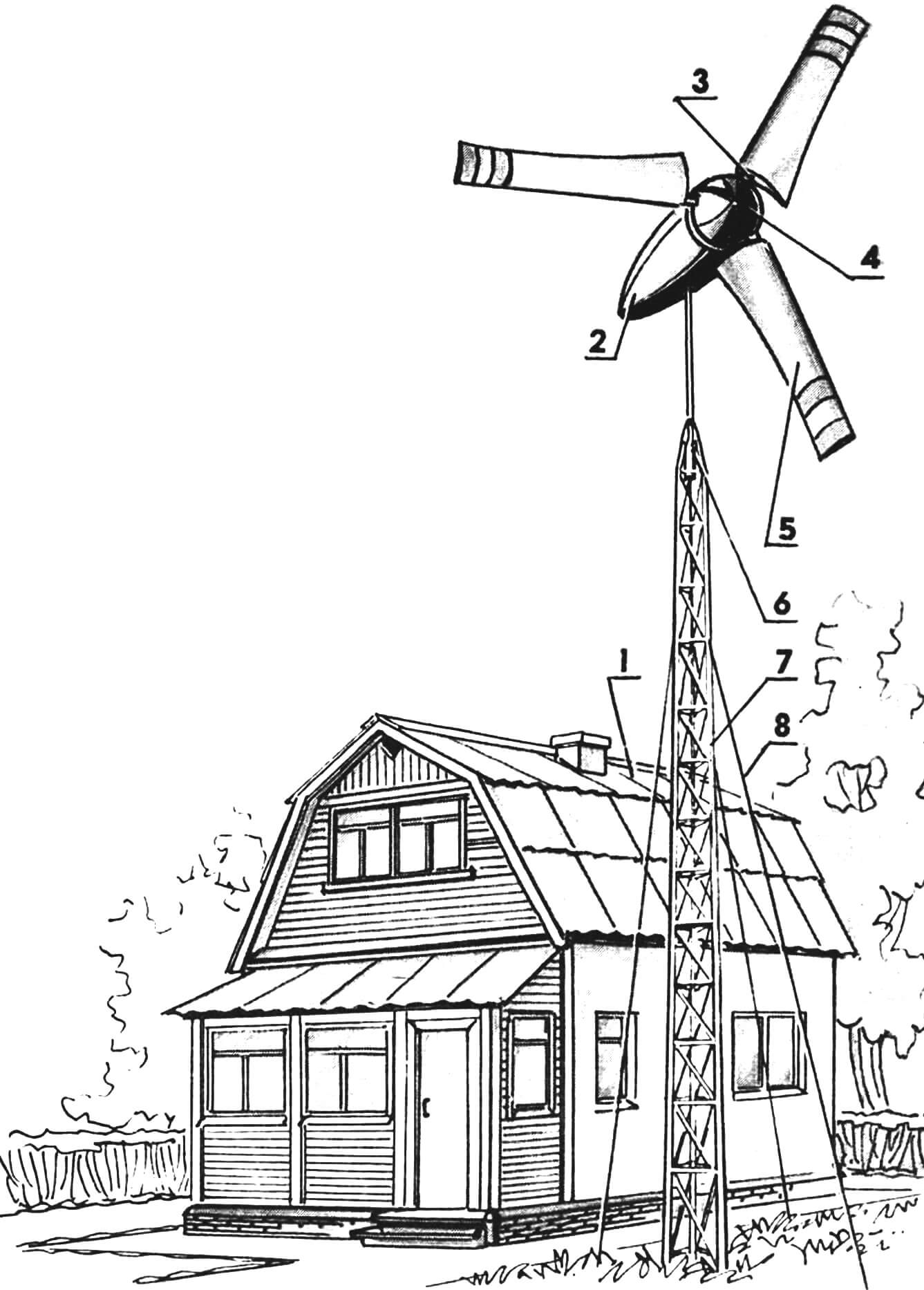
1 — electricity consumer (load), 2 — synchronous electric generator with transmission in the fairing capsule, 3 — blade spar (3 pcs.), 4 — wind wheel spinner, 5 — sail blade (3 pcs.), 6 — slewing support unit, 7 – mast made of metal trusses, 8 – guys.
The “highlight” of the whole structure here is the wind wheel. Firstly, it is bladed. While inferior to the simplest rotary windmill due to its somewhat archaic appearance, reminiscent of the medieval mills with which the notorious Don Quixote fought, this windmill wins in the main thing: the power delivered to the load. Secondly, in this case, paired with the wind… a sail works – on each of the three blades with a variable area Sl and self-limitation provided for strong winds.
The fact is that the blade assembly at the windmill wing consists of a rigid leading edge, ribs of the appropriate section and “twist”, which ensure optimal operation of the end, middle parts and base, as well as the trailing edge, the tension of which is provided by a steel cable. The blade sail is made of nylon impregnated with synthetic varnish. It is stretched onto the frame and secured with a clamping bar on the spacer-base (see figure), and thanks to the cable it is always elastic. After impregnation with synthetic varnish, the fabric has not lost its elasticity at all, and the blade is able to change shape in response to gusts of wind. It automatically adopts the best pitch angle for each specific wind load.
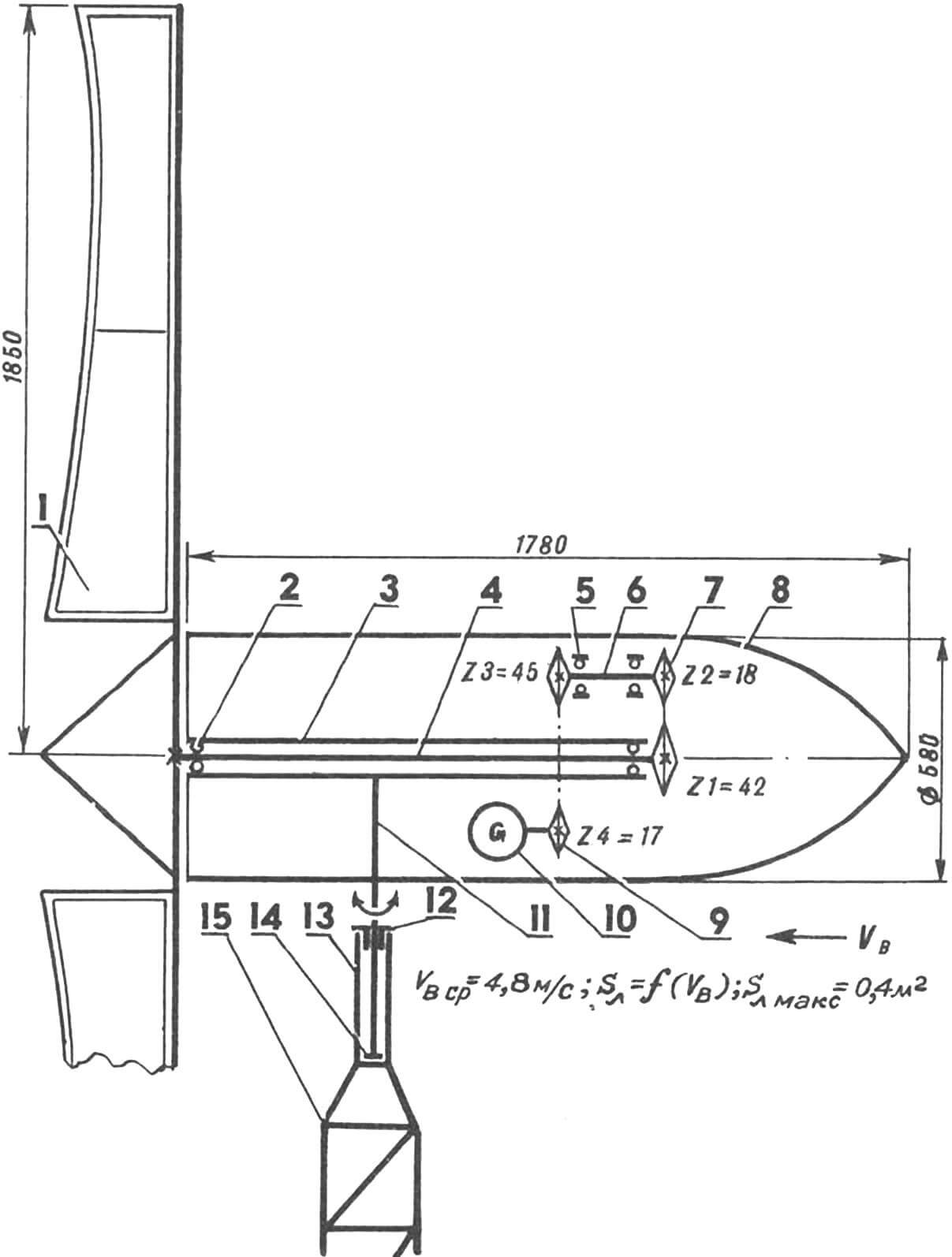
1 — three-bladed sail wind wheel, 2 — angular contact ball bearing (2 pcs.), 3 — square support pipe, 4 — drive shaft, 5 — radial ball bearing (2 pcs.), 6 — intermediate shaft, 7 — power transmission with drive roller chain PR-19.05, 8 – fairing, 9 – power transmission with drive roller chain PR-12.7, 10 – synchronous generator with a power of 1200 W , 11 – internal tube stand, 12 – self-lubricating radial bearing, 13 – external pipe stand, 14 – thrust bearing, 15 – mast made of metal trusses.
Well, if it happens, a hurricane will hit. What then? Nothing bad will happen. The cable that sets the tension on the trailing edge is so tense that at wind speeds exceeding the operating range, the sail falls off and becomes, as it were, inactive: a self-limitation mode arises, and automatically.
Among other technical solutions that successfully fit into the design of this wind power plant, one cannot fail to note the simplicity and reliability of the slewing bearing assembly, the removal of electricity to the load, the use in the kinematic diagram of ordinary chain drives rather than an angular gearbox, and the successful placement of almost all kinematics in a capsule fairing. The capsule itself has proven itself well in practice.
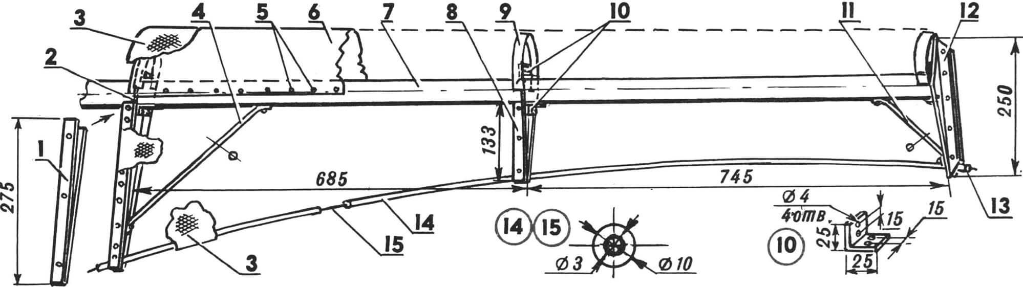
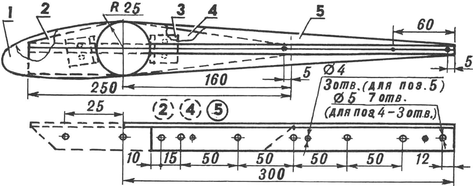
1 — clamping bar (strip with a cross-section of 3X25 mm, AL9-1), 2 — spacer-base (a piece of 25X25 mm aluminum corners riveted and “epoxidized” together to give the desired configuration), 3 — sail (nylon fabric impregnated with synthetic varnish weighing 113, 4 g), 4 – large jib (12 mm rolled aluminum), 5 – rivets, 6 – aluminum casing (6 mm AL9-1 sheet with dimensions 1450X280 mm, giving the desired configuration), 7 – blade spar (1830 mm section pipes 50X3.5 mm, AL9-1), 8 — spacer-middle (a section of 25X25 mm aluminum corners riveted and “epoxidized” together of a special configuration), 9 — “sandwich” rib (blanks riveted and “epoxidized” together from 6- mm sheet AL9-1; 3 pcs.), 10 — docking bracket (20 mm piece of aluminum corner 25X25 mm, 6 pcs.), 11 — small jib (12 mm rolled aluminum), 12 — end piece (piece of riveted together “epoxidized” aluminum corners 25X25 mm), 13 — lead sleeve (12 mm piece of a flattened cylinder with an outer diameter of 12 mm and an inner diameter of 3 mm, 2 pcs.), 14 — cable sheath (two pieces of polyethylene tube arranged in series), 15 – tension cable.
The manufacturing features of the main components, as well as the entire wind power plant under consideration, are a consequence of its originality.
Take, for example, the leading edge of the blade assembly. In essence, this is a coffered structure. It requires a skeleton: a spar with corresponding interconnected elements. And they can’t be made without templates.
You will need six templates. Two – for the blocks forming the ribs, three – for the assembly device of the blade unit (slipway) and one – for the initial rib blank. Their production requires maximum care and concentration, and clean markings.
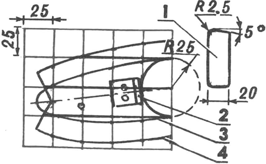
Two templates (see Fig. 6, item 1) are glued to a piece of 20 mm plywood. Following the contour, cut out two plywood pads forming an edge with a hacksaw or jigsaw. Drill 5 mm holes for the center of the spar and assembly markings. A rounding with a radius of 2.5 mm (for bending the flange) and a five-degree cut of the rear corner are performed using a rasp.
The template (item 4, Fig. 6) with a 15 mm flange edge is glued to a 6 mm aluminum sheet AL9-1, which has undergone T4 heat treatment. The resulting workpiece is carefully cut out; the spar center is drilled, and for proper installation on the slipway, the corresponding holes are drilled. This is a kind of new template for making eight more such blanks (3 pieces for each blade).
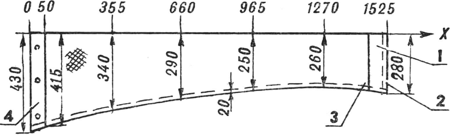
1 – reinforcement strip (75 mm nylon width) of the tip part, 2 – 20 mm seam allowance, 3 – sail fabric blank (nylon folded in half), 4 – base reinforcement strip (75 mm nylon width).
“Sandwich” ribs are obtained by “sanding” the workpieces between two forming blocks (linings). Rigid fixation is achieved by inserting 5 mm bolts through the hole in the slipway and the hole in the spar center into the forming blocks with blanks. And to make the “sandwiching” more successful, future “sandwiches” are clamped in a forge vice. The flanges are bent in the required directions using a rubber hammer.
The flange is formed using lead soft solder. After which the resulting rib is removed, the rear edge is trimmed in order to adapt it to the spar as much as possible. Now comes the rest of the blade parts.
1 — “sandwich” rib (3 pcs.), 2 — “spout” of the spacer-ending, 3 — docking bracket (6 pcs.), 4 — shank of the spacer-ending and (the same part) spacer-middle, 5 — spacer-base.
The docking brackets are made from aluminum angle 25X25 mm. Spacers are also made from it to hold the rope and tension the trailing edge at the base, in the middle and at the tip of the blade. They are made in a very unique way: not from one, but from two pieces of aluminum angle, riveted and “epoxidized” together. The length of such a workpiece is 2.4 m. In its cross-section, it resembles the letter T. High quality of the seam is achieved by thoroughly cleaning the surfaces before joining them, for which they use strong detergents, followed by rinsing with water and wiping until shiny with a metal “tangle”.
1 – forming block (20 mm plywood), 2 – docking bracket, 3 – contour of the wooden block, as well as the second layer of the sandwich rib, 4 – first layer of the sandwich rib.
The desired shape of the spacers is achieved using a hacksaw. And the cutout for the spar, rivet and cable holes are drilled with an electric drill. As well as the holes in the spacer-base for subsequently attaching a clamping bar in order to reliably hold the sail on the blade even during the heaviest wind loads. As for the docking brackets, they are riveted and “epoxidized” to the spacers (see illustrations), and to the “sandwich” ribs, and to the blade spar. Moreover, it is more convenient to do this on a special device – a slipway, which ensures uniform execution of the blades and correctly sets the pitch angles.
Here is one such operation.
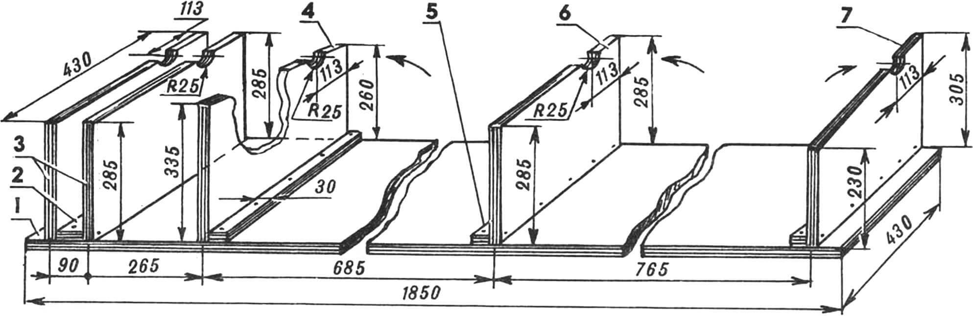
1 — base, 2 — spacer, 3 — blade spar fixing post (2 pcs.), 4 — template for performing work on the base of the sail, 5 — reinforcement bar (3 pcs.), 6 — sail center post fixing, 7 — stand for work on the tip. All parts of the slipway are made of 20 mm plywood, fastening is done with screws. The arrows indicate the directions in which the “sandwich” ribs are attached to the slipway in the places provided for them.
The “sandwich” ribs are bolted to the slipway in the places provided for them (in the directions indicated in Fig. 7 by the corresponding arrows, and along the installation holes, which are made both in the slipway and in the ribs themselves). Then, starting from the end, carefully lay the “side shelves” of the cable struts on the “pedestals” intended for them, the ends of the plywood protrusions located at the required angles to the base: stand 7, retainer stand 6 and template 4 (see Fig. 7). The blade spar is threaded into the holes formed on the slipway; fortunately, semicircular recesses with a radius of 25 mm are specially provided for this purpose.
Mark the rivet holes in the spar. Then the latter is taken out and holes are drilled in it. And having installed the spar again in the slipway, they riveted and “epoxidized” the docking brackets.
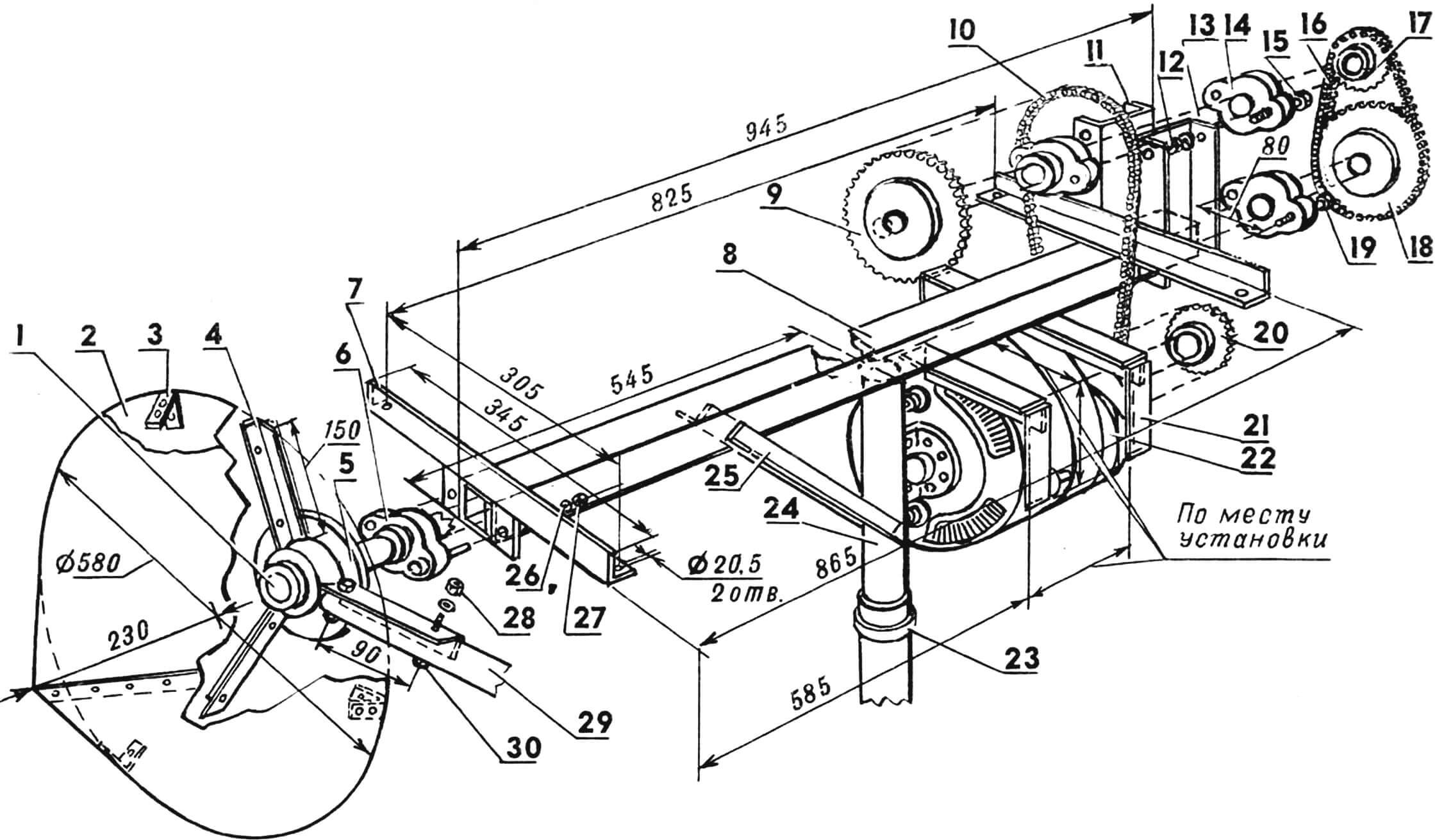
1 — drive shaft (diameter 25 mm, length 1500 mm, Steel 45), 2 — wind wheel spinner (D16), 3 — holder (section strip 3X25 mm, St3, 3 pcs.), 4 — welded hub spoke (steel angle 25 X 25 mm, 3 pcs.), 5 — hub (Steel 20), 6 — bearing assembly of the drive shaft (2 pcs.), 7 — horizontal bracket (steel angle 25X25 mm, 2 pcs.), 8 — steel support pipe ( in cross-section – square 50X50 mm, wall thickness 4 mm) with welded square steel 4-mm cheeks at the ends, 9 – sprocket Z3=45 (Steel 45), 10 – chain PR-12.7, 11 – vertical bracket (300- mm piece of steel channel No. 8, welded to the side walls of the support pipe), 12 – M14 nut with Grover washer (4 pcs.), 13 – intermediate shaft (diameter 20 mm, length 350 mm, Steel 45), 14 – intermediate bearing assembly shaft (2 pcs.), 15 — M14 bolt (4 pcs.), 16 — PR-19.05 chain, 17 — sprocket Z2=18 (Steel 45), 18 — sprocket Z1=42 (Steel 45), 19 — M18 bolt (4 pcs.), 20 — sprocket Z4=17 (Steel 45), 21 — box-shaped bracket (dimensions at the installation site depending on the type of generator, St3, 2 pcs.), 22 — electric generator, synchronous, power 1200 W , 23 – slewing bearing, 24 – internal steel pipe stand (length 90 mm, outer diameter 60 mm, wall thickness 4.5 mm), 25 – welded jib (305 mm piece of steel angle 25X25 mm, 2 pcs .), 26 — lock washer (4 pcs.), 27 — M18 nut (4 pcs.), 28 — M12 self-locking slotted nut (6 pcs.), 29 — blade spar (1830 mm pipe section with an outer diameter of 50 mm and wall thickness 3.5 mm, AL9-1, heat treatment mode T6, 3 pcs. ), 30 — M12 bolt (6 pcs.).
The aluminum sheathing of the leading edge of the blade is made from 6 mm AL9-1 sheet, having previously bent it in the form of a parabola. Moreover, the latter is best done on a flat floor using a long board laid edgewise along the bending axis. Resting your knees on the board, your hands and your whole body create the necessary pressure on the sheet, achieving the desired shape.
The next operation is to attach the casing to the blade skeleton. In this case, it is advisable to use special C-shaped clamps (not shown in the illustrations).
1 — main frame (multi-layer plywood, 3 pcs.), 2 — longitudinal hatch panel (12 mm plywood, 2 pcs.), 3 — spar (multi-layer plywood strip, cut with a bend after the 3rd frame, 4 pcs. .), 4 – M16 bolt connection with self-locking (8 pcs.), 5 – bracket-guide (100 mm piece of steel angle 40X40 mm, 4 pcs.), 6 – sheathing strip (plywood, tapering in width after deflection by 3 m frame, 23 pcs.), 7 — transition frame (20 mm plywood), 8 — end frame, 9 — fiberglass covering, 10 — cone-shaped nozzle (maximum diameter 386 mm, foam), 11 — transverse hatch panel ( 20 mm plywood).
Starting from the tip, drill rivet holes in the covering, spar and ribs. The parts to be joined are “epoxidized” and glued. And after the “epoxy” has completely hardened, the “excess” aluminum is trimmed and the resulting sharp edges are filed.
Now a few words about the trailing edge of the blade. It is mounted with a 3-mm flexible steel cable, which is threaded through the holes provided for it in the spacers. The cable is installed in vinyl chloride tubes and secured at the end, clamping it in a lead sleeve. After which the sail is pulled over the blade skeleton.
1 — welded bracket (steel angle 25X25 mm), 2 — rivet (4 pcs.), 3 — electric cable, 4 — terminal and connection to the contact brush (2 pcs.), 5 — electric cable core (2 pcs.), 6 — 5 mm fiberglass plate, 7 — stop-bracket (aluminum corner 12X12 mm, 2 pcs.), 8 — spring with contact screw (2 pcs.), 9 — socket-guide (aluminum square section pipe with fasteners, 2 pcs.), 10 — contact brush (2 pcs.), 11 — insulated electrical wire (2 pcs.), 12 — internal steel pipe stand, 13 — brass ring with contact screw (2 pcs.), 14 — textolite bushing with two set screws, 15 — comb washer (St3) with two set screws, 16 — self-lubricating radial bearing (AFGM), 17 — outer steel pipe stand, 18 — thrust bearing (BrAZh9-4), 19 — M24 bolt with nut and fixation puffs.
It is better to perform such a responsible operation together. One person stands on the table, holding the blade in his hands so that the base spacer is at the bottom, and the trailing edge cable is positioned vertically with a two-pound weight hung at the end. Then the other (assistant), making sure that the required tension has been achieved, presses the second lead sleeve located at the base spacer onto the cable. The excess cable and sleeve are ground off. And the “open” end of the sail is wrapped and then secured to the base spacer using a clamping bar and bolts and nuts.
The remaining blades are made in the same way. As for other components and parts, their implementation, as a rule, does not cause any particular difficulties for anyone. The same can be said about the assembly of the entire wind power plant as a whole. Easy to debug. Go for it!
MAIN CHARACTERISTICS OF WIND POWER PLANT
Range of operating wind speeds, m/s 3—20
Power supplied to the load, W 1200
AC generator , synchronous
Three-blade wind wheel, self-aligning in the wind flow
Wind wheel diameter, m 3.7
Sail blade, with variable area and self-limiting
Dimensions of fairing with power section, mm Ø580X1780
The material was prepared for publication by N. KOCHETOV
Recommend to read
 THE MAST ON THE ROOF
It is probably impossible to imagine a contemporary house without radio and television. But for good reception of distant stations, TV channels (as well as for individual... HAMMER IN THE MAIL
Of all the impact tools — an axe, a sledgehammer, a pick, and others more in the process suffers hammer: slip a large nail or chisel is not lost on its wooden handle. To protect her from...
