
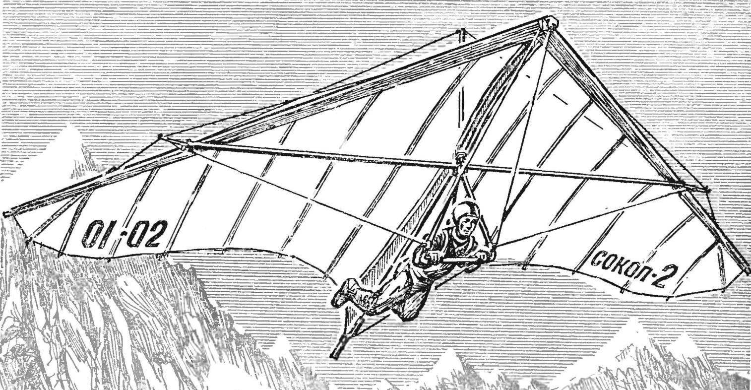
 The best Amateur-built glider, took part in the competition “Dombai tops” in 1978, was named “Sokol-2”. Its Creator — Leningrad master of sports V. D. Mikhailov, a renowned specialist in the design and making of yacht sails. So it is understandable his desire to use when constructing the glider, the latest achievements in the field of sailing. As a result, the quality of the dome “Sokol-2” had no equal among the devices flying over the Caucasian peaks.
The first flight V. D. Mikhailov with Youth at the “Russian fields” (elevation about 800 m) present experts noted only the correct profile and high-purity forms of its apparatus.
What are the features of this glider? To frame it a little different from the traditional one (Fig. 1). Significant can only be considered the front keel tube, forming a shackle with a height of 130 mm to give a favorable profile of the Central part of the dome, and mount ropes — stretch marks side pipes, providing the necessary flexibility: flexible design to some extent, capable of self-regulation, for example, the elastic damping sudden gusts of wind.
Today it is still difficult to say how correct in my assumptions V. D. Mikhailov; however, remember that the bird’s wing is also very flexible and elastically responds to changes in direction and strength of air flow. One thing is certain: to make progress in any business, and especially in such a new and poorly understood, like hang gliding, you need search and be sure of the flight experiment. A flying “Falcon-2” excellent, and not only in the hands of its Creator: the other pilots who tested the glider, also gave a good opinion about its flight qualities.
During a scientific conference held in Dombai, V. D. Mikhailov made a detailed report about the features of the device, and in particular on the method of cutting and sewing of the dome. Given this brief information and drawings of hang glider “Sokol-2”, submitted to the editorial Board by the author.
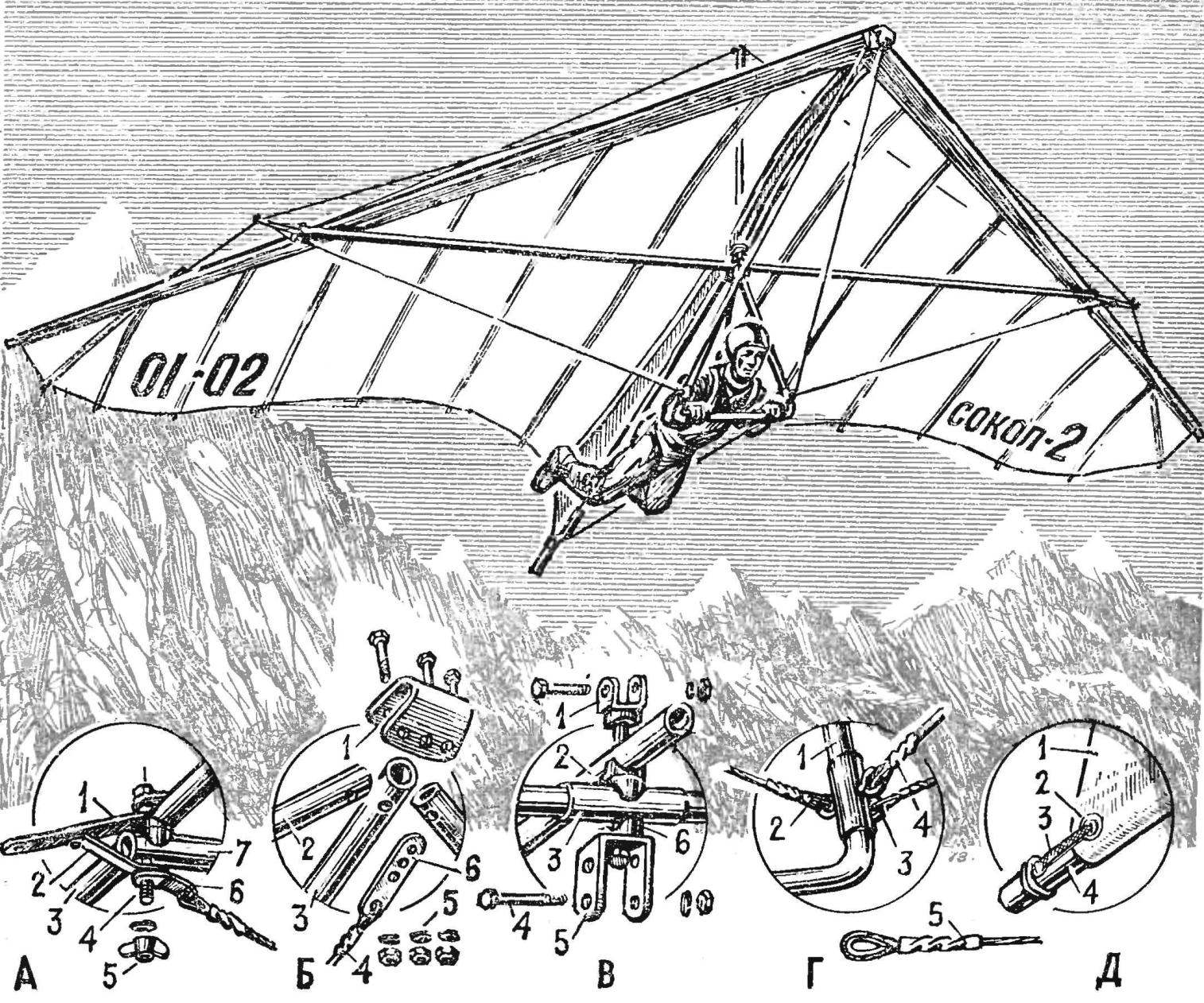
Fig. 1. The overall layout of the glider “Falcon-2” design of the master of sports V. Mikhailova (St. Petersburg):
A — node connections of the transverse and lateral pipes: 1 — the gaff rig, 2 — brace crispity, 3 — side pipe 4 — bolt M8, 5 — wing nut M8, 6 — lug cable cross-wire, 7 — transverse tube; B — the front attachment point of the keel and side of the frame tubes: 1 — yoke, 2 — side pipe, 3 — keel, 1 — wire stretch, 5 — M8 nut, 6 — strap rope stretch; — the Central node: 1 — the base of the mast, 2 — the keel 3 — a coupler cross pipe, 4 — M8 screws (for mounting the steering linkage), 5 — bracket steering linkage, 6 — notched washers; G — unit cables to the steering linkage: 1 — trapezium, 2 — rear cable 3 — side cable, 4 — front wire, 5 sealing the end of the rope onto the thimble with a twist in the copper tube; — mount the keel of the dome: 1 Kil, 2 — lyuzers, 3 — Mylar tape or cord 4 — the keel.
In his time, at the dawn of aviation, and today, at the dawn of hang gliding, almost every pilot is both the designer and the manufacturer of your machine. Even when a enthusiast is taken to build the glider according to the already approved drawings, he always makes something different — either consciously or involuntarily, due to the lack of recommended materials. And if you can purchase everything you need to make all items on high technological level — from experiment to resist and impossible.
Watching the behaviour of the canopy-glider in flight, I came to the conclusion that most of the devices it is filled with air as it should for maximum lifting force (and its value ultimately depend on the performance of the apparatus). For many years, doing sailing, I knew exactly what form have to have a good sail, so that he could provide maximum thrust for a given wind. And since the words of the famous Russian pilot P. Nesterov, “in the air everywhere support” — the value of the thrust for a sail similar to the lifting force for the dome of the glider. Therefore, the dome of the glider should be cut out and sew, like the best types of sails (any sample — “Bermuda grotto”). The dome needed to be made in the form of two such sails are sewn with each other their bases (bottom skatinami). This Central seam can be laid any desired curve (e.g., S-shaped profile), which with the help of the keel pocket will always retain its shape in flight, that is, in other words, to withstand the most advantageous aerodynamic profile. And sewing technique (see Fig. 4) will preserve this favorable profile to the end of each wing (console), enabling several to modify for a so-called “twist”.
The design of the seams is given in relation to the calendered polyester.
Manufacturer of a sail begins with a drawing in full size on a level floor or asphalt pad of figure 2 in plan view with a mark all the major lines as well as lines of the seams connecting the panels. It is clear that their location should correspond to the width of the available material. Then, applying the material to the drawing, it is cut into pieces of desired length, from centerline to the ends of the consoles. To save, cutting off the first piece, the roll can be rotated to a second piece lay exactly along the lines of the side of the pipe. Cut into desired number of pieces (it can be different, depending on the width of the material) and laid it out on the drawing, mark out the floor seams a soft lead pencil or marker in accordance with the scheme shown in figure 2. The edge of the top cloth is cut on the profile line (shown by number with the + symbol ), the bottom — line.
Experienced sailmaker sew calendered Dacron without prior tacking or gluing, just laying the material in the machine and slipping it under foot made in accordance with pencil markings. Beginners it turns out far not at once; therefore do not be in a hurry and upset at the failures. It is convenient to perform this work together.
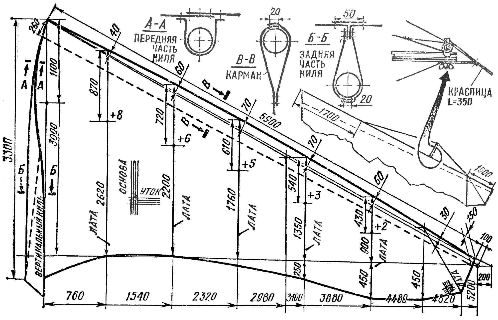
Fig. 2. The theoretical drawing of the sail and the design of the major joints.
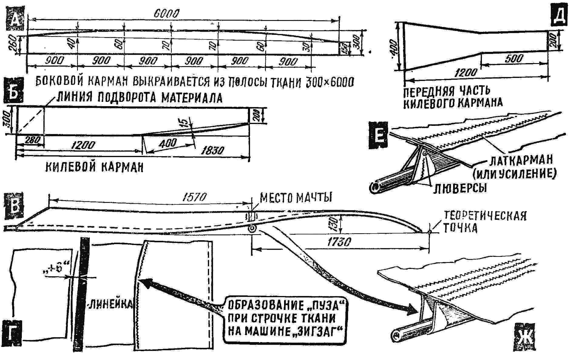
Fig. 3. Details of the sail and tailoring of panels to obtain an airfoil:
A — side pocket (each sewn two strips of fabric into the distance curved the line); B — keel pocket (back); C — keel pocket (the projection of the side view); G — formation of “belly”: the edge of the upper cloth having a curved line that is sewn to the bottom with straight edge; the curvature of the upper cloth is determined by the flexible ruler and the figures shown in figure 2 with the sign +; D — anterior part of the keel pocket, cut out along the base (common thread); E — the position of the keel pocket on the center support tube (rear view); G — position the front pocket on the Central tube.
There are two ways to connect panels: two in pairs, then sew two pairs, etc. the Second method is straight line, from wingtip to root, with a shift of the seam in the external from the vehicle side (in this case, under the yoke of the machine will always be only one the fabric).
The described technology allows tailoring to sail, which is in advance imparted the desired profile. This eliminates the need for various additional means of tensioning (rubber stays attached to the mast, etc.).
The first flights confirmed the correctness of my calculations. After the minimum run-up of the dome was filled with air, acquired firmness and quickly pulled up, and in flight was very stable and well obeyed controls. It also describes the sail completely silent in flight: it is unusual zapalskiene rear edge, a sharp whistle, and more.
I think that, in this way, you can create an even better aerodynamic attitude of the glider, even without changing the design of the frame, but only a few varying the vertex angle. Everything else can be achieved by improving the quality of the sail, the capabilities of which we still know very little!
V. MIKHAILOV, master of sports of the USSR, Leningrad
Recommend to read
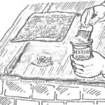 FIX THE ROOF
If you have a house or garden leaky roof — burst slate, rotten boards, rusted sheet metal, it can be easily repaired, placing the patch. The damaged area liberally spread with nitro,...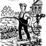 NOT LEVER AND SWITCH
The development of the garden or suburban area, many owners have to start with providing it with water. Since this problem started and I. The water in the area lies relatively close to...
