 Almost all users as a stationary radio stations (including those intended for civil radio on 27 MHz), and automobile radios and 4M AM (amplitude and frequency modulation) are faced with the need for optimal coordination of antenna-feeder devices (hereinafter — AFD) with the transmitter. To increase the range of a portable (wearable) mobile stations are sometimes also connected to respective external antenna, for Example, in the CBS range on an antenna called “5/8” vertical polarization and pin around 1450 mm That is the solution of the mentioned problem is important for all radio Amateurs with an active and effective (long-distance) communications.
Basically an external antenna transceivers and radio stations (balcony, roof, motor with different mounts) must be confirmed by the transmitter of the radio to a certain frequency (for example, to 27.0 MHz) AFU were minimal losses. Almost all hams know about it If this is not done, the output power of the transmitter is used inefficiently, to achieve the maximum distance of operation of the radio will be difficult To reconcile is the meter’s standing wave ratio (hereinafter SWR). However, there’s no rush for that device in specialty stores — where he is from 600 rubles. Those who rarely repairs and adjusts radio, use for tuning and matching of transceiver and antenna-feeder device services “field experts” that today costs also very expensive, as with any work in the field of maintenance and repair, although the specialists are all the same meters the SWR is not So easy to collect it for their needs yourself? For those radio Amateurs who are willing to DIY SWR and how to use them, I suggest to use the following recommendations.
To obtain highest efficiency operation of the transmitter, CB radio it is necessary to provide an active output resistance of the transmitting node equals to the value of the characteristic impedance of the cable (feeder), and it, in turn, should correspond to the resistance value of the emitter (antenna pin, if to consider a simple antenna design).
Coordination of the feeder and the pin is the coil inductance and capacity (a trimmer capacitor) installed, usually at the base of the antenna it will need to collect matching device with SWR, which is shown in figure 1.
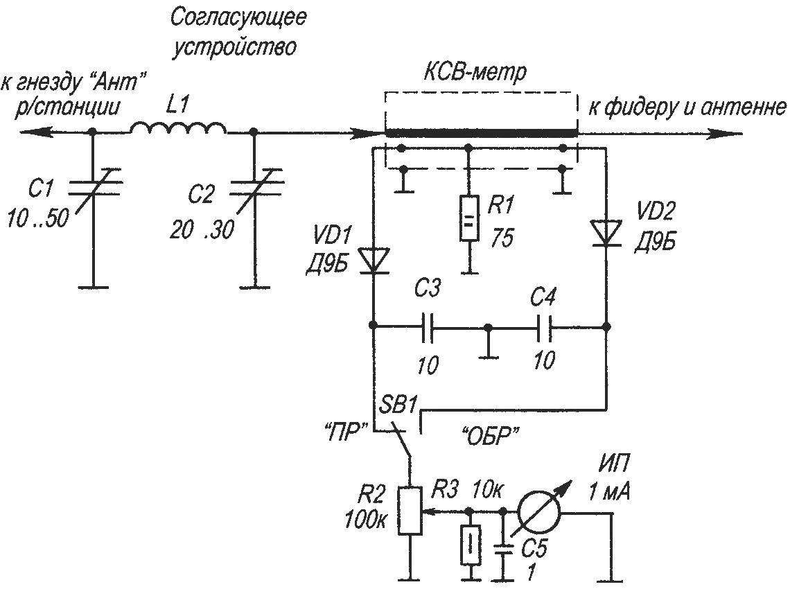
Fig. 1. A circuit diagram of the matching device with SWR
Matching device consists of two adjustable capacitors C1 and C2 with an air dielectric, for example KPE-4…50.1 per CLMV-1 and frameless inductance coils L1 It contains 8 coils 2,2 mm copper wire without insulation with a diameter of winding 25 mm and a length of 22 mm. the Inductance of a coil will be 1.2 µh setup approval is made by the capacitors C1 and C2. Values off on SWR, which shows how close to the mode traveling wave (no signal reflected from the load) the system is in “radio — feeder — antenna”.
A matching device is connected to the aerial socket of the transmitter by using a cable cut (m) with characteristic impedance of 50 Ohms, for example RC-50.
The SWR meter consists of a segment of the same cable type RK-50 length 160 mm with removed outer insulation of the cable cut after all the preparatory work to bend a horseshoe. The screen wires connect to ground transmitter External view of completed segment of the cable shown in figure 2.
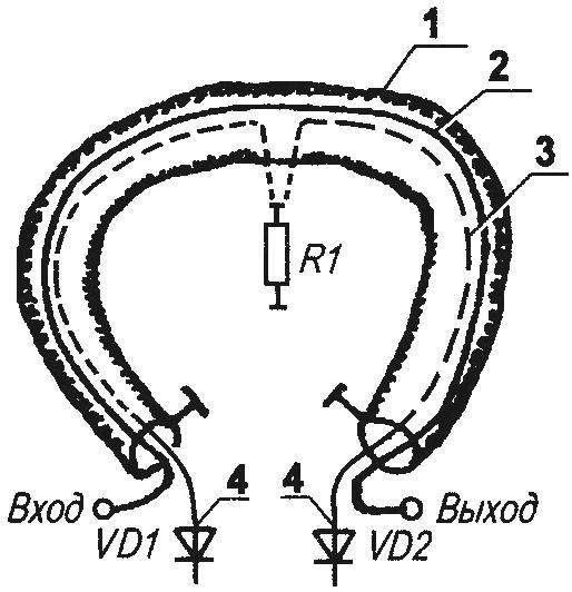
Fig. 2. Cable RK-50 for SWR meter:
1 cable with remote external insulation (IC-50, L1000), 2 — lived internal cable; 3 — insulated wire type MGTF-0,8; 4 — germanium diodes VD1, —VD2 (series D2, D9, Д220, Д330)
The inner core of the cable respectively connected at one end to a terminating device (capacitor C2), and the other to the antenna lead Inside the shield wire on the SWR meter (cable cut length 160 mm with removed insulation) gently with a needle to navigate a flexible insulated wire type MGTF-0,8 and from the middle make the outlet connection of the resistor R1, the Ends of the inner wire MGTF-0.8 mm (can be used with any similar wire MGTF-1, MGTF-2) soldered to the germanium diodes VD1, VD2.
Permanent capacitors — tubular Resistor R1 with a power dissipation of 2 watts, for example MLT-2 the resistance can be in the range of 30 — 150 Ohm fixed resistor 143 is of the type MLT-0,5. Variable resistor 142 is of the type SPO-1 as diodes VD1, VD2 are used germanium diodes of series D2, D9, Д220, Д311 with any alphabetic index.
Measuring device — any graduated, with the current full deflection of 1 mA. Switch SB1 — type switch, for example MT-1
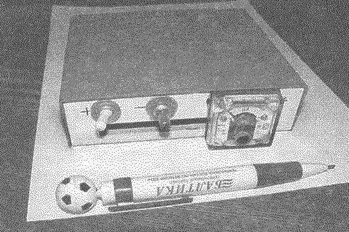
Case for SWR can be selected to be any suitable, shielded. The finished device looks like (for example, as in the original) as shown on the splash screen Before you turn on the radio and the matching device is carried out the necessary preparatory work connect the antenna-feeder device, set the switch SB1 to “PR” (left scheme) and the slider of the variable resistor R2 is in the middle position Then do the matching and define the CWS.
After power on radio and including it in a mode “transfer” the movement of the engine, the variable R2 resistor achieve the maximum deflection of the milliammeter to the right, for example, as the number “10” (if this figure is the maximum graduated value scale) is then transferred to the switch SB1 to “ARR” and record the new scale reading of the instrument (much less than the previous), which corresponds to a value of the backward wave.
According to the following formula SWR = (CPD+Pobr)/(PPR-Pobr) find the value of the CWS RRP — reading device in the capture mode of the direct wave (switch SB1 is in the left position according to the diagram) But — reading device with feedback such as, PPR = 10, But = 2, then the CWS = (10+2)/(10-2) = 12/8 = 1,5.
The loss of the reflection wave circuit “transmitter — feeder — antenna” depend on the value of KSV can be determined according to the table below.
The dependence of the losses of the reflected wave from the CWS
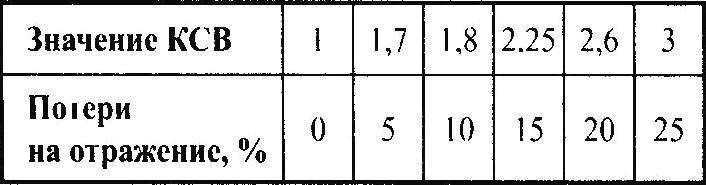
For optimal coordination, it is desirable to set the SWR between 1.7 and 2, in this case, the reflection loss of the wave will be 5 — 12%, which is quite acceptable.
Assuming constant length of the probe antenna by changing the capacitance of the capacitors C1 and C2 of the matching device, as well as changes in the capacitance of trimmer capacitor at the base of the antenna to achieve the necessary VSWR If the antenna pin (and in some models and its “counterweight”) structurally has the ability to adjust the length, it is the additional lever configuration of the entire system of harmonizing This simple method you can use to configure Amateur radio transceivers, CB range, automobile radios operating in the CB frequency of 27 MHz, with output power 2 15 watts and is equipped with simple antennas.
A. KASHKAROV
Recommend to read
 GAZ-31105 “Volga”
Serial production of the GAZ-31105 "Volga" started on 18 may 2007. The interior of this model was developed by the specialists of the Gorky automobile plant in cooperation with German... PHONE ON SUCKERS
It is very inconvenient to dial the number, if the unit is on a smooth polished surface. The phone slides that sometimes leads to the wrong set. To get rid of such unpleasant properties...
