
 Readers of radio-controlled model copy of the missile and aircraft interceptor BI-1, the parameters of which correspond to rocket gliders S8F Recall that this flying class combines the model with a mass of 500 g with engines of 40 — 80 N.with. Among the requirements for models of this class — the prohibition of splitting the model into two or more parts (including the engine after the trigger should remain in the container). Besides the active part of the flight (take-off) should be straightforward — ascending spiral and loop invalid. Maximum measuring time of flight of the models in this class is 300 seconds.
The fuselage of the model — bearing type, Its basis is formed by two symmetrical power sides, stringers and cross-set (frames).
Frames cut from a composite material, consisting of a balsa plate thickness 3 mm, strengthened thin glass For production of such material is convenient to use two sheets of thick plexiglass, to which epoxy binder privorovyvat pieces of thin glass, and then between them is the balsa plate Prefabricated to cure the resin pressure test using the load the result is a durable and lightweight billet Side — the balsa from blanks with a thickness of 3 mm.
The Assembly of the fuselage is easiest to lead into the stocks, which is a wooden block with a cross-section of 70×30 mm and length of 600 mm, the narrow side of which is in accordance with the drawing of the fuselage you-milled grooves with a width of 5 mm the Frames are temporarily secured in the slots by means of wooden wedges, after which they are adjusted and glued the balsa sides, and then the balsa stringers of triangular cross-section with sides 6×6 mm the Assembly is made using plasticized epoxy resin After curing of the glue the fuselage is removed from the pile and on it are mounted the spacers, crossmember for mounting the steering servos of the Elevator and a cross member affixed to it a nylon nut M3, designed for wing mounting.
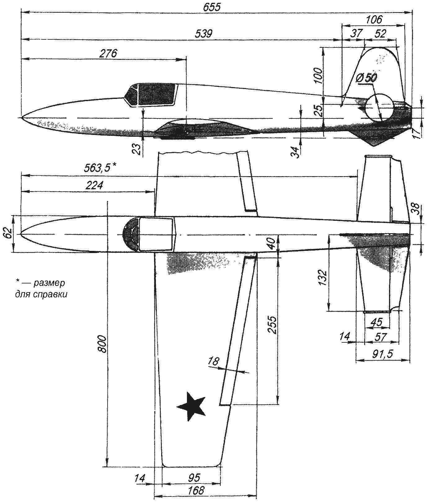
The geometric scheme of radio-controlled models-copies of a rocket fighter-interceptor BI-1
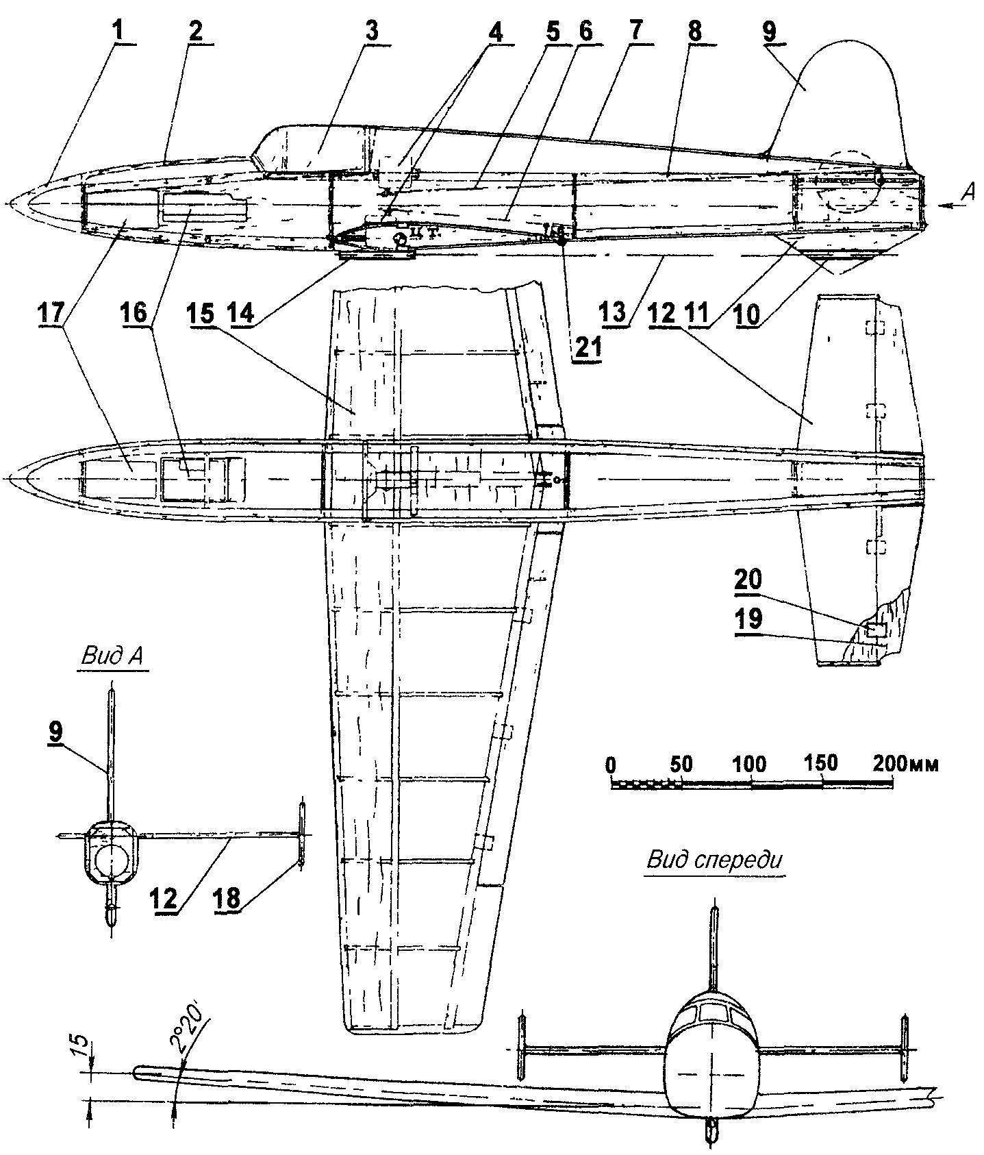
The layout of rocketmodel:
1 — Kok of the fuselage (balsa), 2 — front fairing (balsa), 3 — flashlight, 4 — servos of a control system, 5 — axis traction drive elevators, 6 — axis linkage actuator Aileron, 7 — rear fairing (balsa s2), 8 — skeleton of the fuselage, 9 — keel (balsa s3), 10,14 — start guides (duralumin tube with an inner diameter of 4 mm), 11 — fairing (balsa s5), 12 — stabilizer (balsa s3), The 13 — axis Central starting pin, 15 — wing 16 — receiver, remote control equipment, 17 — the battery pack, 18 — spacer (balsa s4), 19 — Elevator (balsa s3), 20 — hinge hinge rudder (nylon), 21 — M3 screw wing mounting
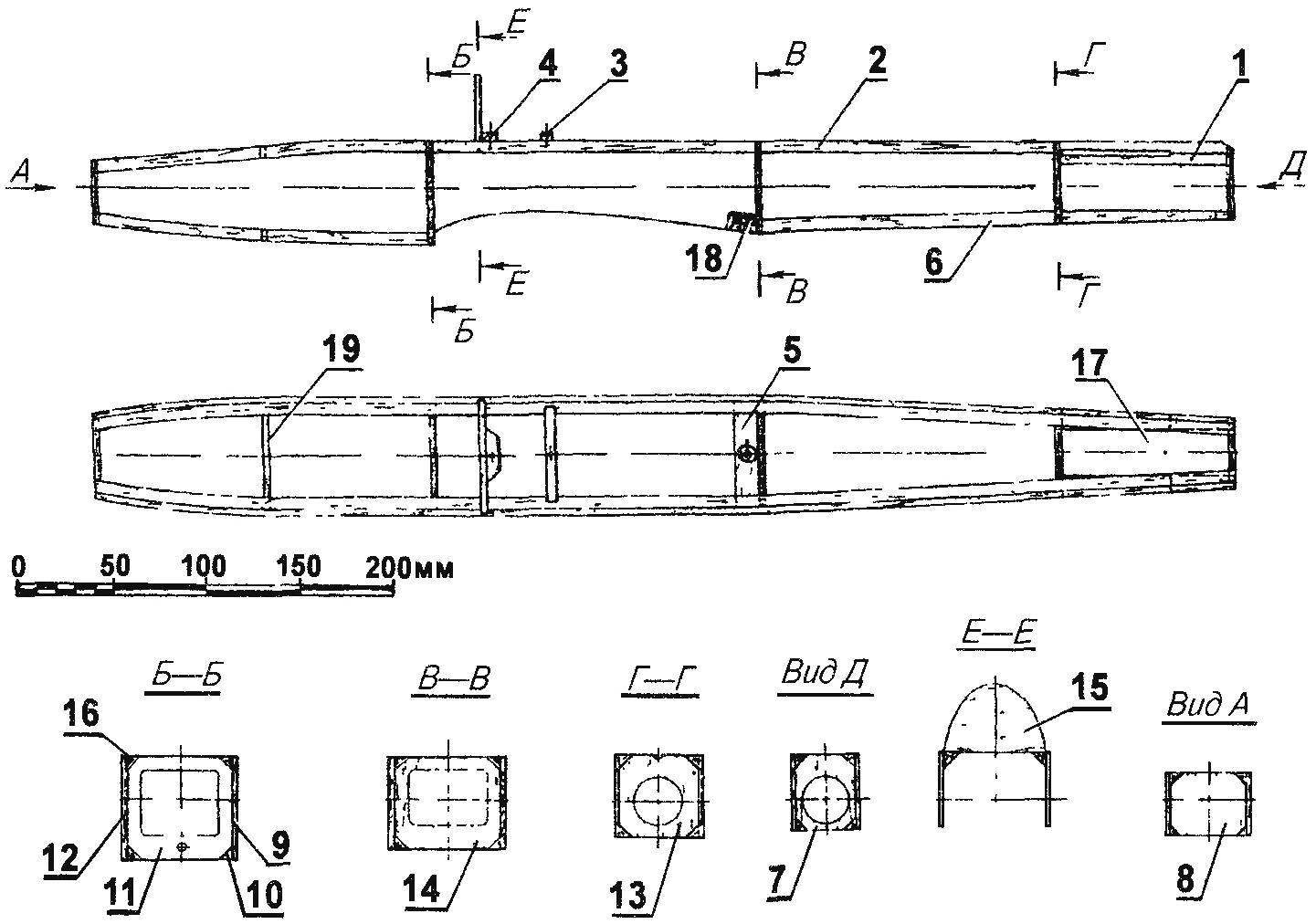
The layout of the skeleton of the fuselage:
1 — stabilizer base (balsa rail 6×6), 2,6,10,16 — stringers (balsa rail of triangular cross-section 3×3), 3,4 — cross member supports the steering servos (beech, rail 4×4), 5 — crossbar mounting wing (pine, rail 8х15), 7,8,11,13,14 — frames (fiberglass reinforced balsa, s3), 9,12 — side of the fuselage (balsa, s3), 15 prosperous top (balsa s3), 17 — a glass under the model rocket engine (Vileika of fiberglass with an internal diameter of 20.5 mm), 18 — M3 nut (nylon), 19 — spacer (pine, 6×3 rail, 2 PCs)
In the tail part of the fuselage is glued a thin-walled fiberglass glass with an inner diameter of 20.5 mm for model rocket engine Kok fuselage carved from balsa in the same way and made the fairing front upper part of fuselage in front light Fairing rear fuselage bent balsa plate thickness of 2 mm.
Keel, stabilizer and elevators — seleblitie Latter is connected a cover plate made of solid wood, which is attached pylon drive steering Themselves the elevators are hinged to the stabilizer with balsa embedded in the nylon loops At the back of the fuselage is installed the balsa triangular plate (fairing tail crutch) fused in her thin-walled dural tube with an internal diameter of 4 mm starting guide a Second tube secured with thread and epoxy under wing.
The wing has an asymmetrical lenticular airfoil NACA 2411 with a relative thickness of 11% Wing — stacked, with dvukhpolosnykh pine spar, balsa leading and trailing edges and balsa ailerons the same To the Central part of the wing and glued the balsa lugs in the front embedded 3-mm beech pin mounting wing, while the rear has the slot under the steering machine control the ailerons the Forehead of the wing and the Central part with a hard 1.5 mm balsa covering, the covering wing of the Mylar film.
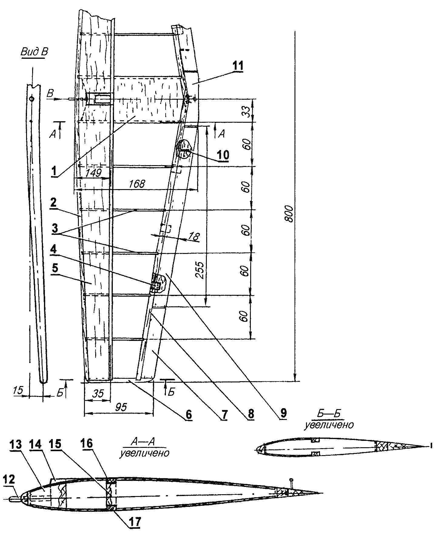
The design of the wing rocket models:
1 — the lining of the Central part of the wing (balsa, s1,5), 2 — front edge of the wing (balsa rail 10×5), 3 — rib (balsa s), 4 — hinge Aileron hinges (nylon), 5 — stripe forehead wing (balsa, s1,5), 6 — wing tip (pine, 12×6 rack), 7 — filling (balsa, s6), 8 — trailing edge (balsa, raked 7×7), 9 — Aileron (balsa, 20×6), 10 — torsion actuator Aileron (Bicycle spoke), 11 — filling of the Central part of the wing (pine, rail 20×6), 12 — pin fixation wing (beech, rod Ø3), 13,15 — boss (balsa), 14 — Playground (balsa), 16,17 — beam flange(pine, rack 8×3)
Table of the coordinates of the airfoil NACA 2411 with a relative thickness of 11%

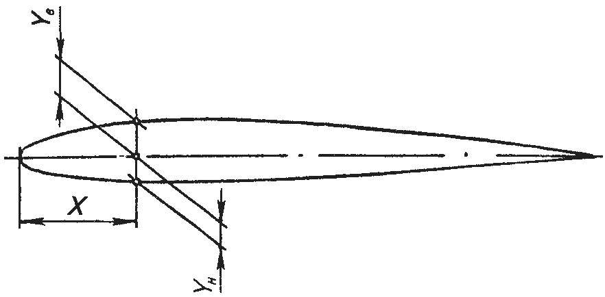
Build the profile of the wing of rakatomalala (PASS-2411 with a relative thickness of 11%)
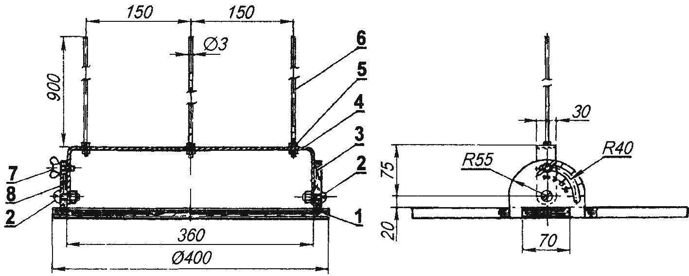
Starting device:
1 — base (plywood s12), 2 — axis swivel clamps (set screw M6 with nuts), a 3.8 — brackets (plywood s8), 4 — clip (made of anodized aluminum, strip 30×4), 5 — mounting lugs (nut M3 6 PCs.), 6 — pin (steel, wire-Serebryanka Ø3, 3pcs), 7 — the screw-“the lamb” M6
Starts rocketmodel class S8F
The Assembly of the wing it is desirable to produce in slipway, made of three boards section 20×150 mm, mounted on two tool trays the form of the latter is determined by the configuration of the wing when viewed from the front — taking into account the cross “V” Ailerons mounted on the wing with nylon hinges — the same that are used for suspending the Elevator Actuator Aileron is made using cuts of steel wire with curved ends at one end of the bent ring for connection with a thrust from the steering machine, and the other, sealed the Aileron is cut the wing mounts to the fuselage is made using beech pin (front) and M3 screw (rear).
The starter is a plywood circle with a diameter of 400 mm, on which are mounted two brackets with hinged them in a U-shaped aluminum bracket On the bracket with three fixed pins made of steel wire with a diameter of 3 mm Central guide and a pair of side supporting Bracket can be rotated and locked with wing screw — this allows you to choose the best angle to start the model.
This article was prepared using materials from the American magazine Radio control modeller
Recommend to read
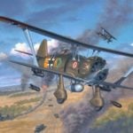 “ANGELS” IN THE SKY OF SPAIN
Dive bomber, the Hs-123. After the First world war power aviation enterprises in Germany decreased significantly. The restrictions imposed by the Versailles Treaty, in fact, deprived the... ONE-STORY, BUT WITH ATTIC
The beginning of the nineties were particularly unpredictable are growing by leaps and bounds. Of ordered structures in my summer cottage, the builders made the walls to the chopped bath...
