
 The court, using for movement the muscular strength of a man, never belonged to the category of speed. The only exception is racing boats for rowing, which is the most fleet of vessels musculoides. Due to their known good configuration and the most complete use of the muscle energy of athletes, boats-“eight” is capable of two-kilometer distance to reach the speed of 12 knots. But this does not mean that this speed is the limit of possibilities of human movement on the water surface. If you deviate from canonical constructions of rowing boats, designed for official competition, then there is a possibility of creating a spacecraft-muskurahaton reach speeds up to 20 knots!
When designing high-speed non-motorized vessels the designer must solve two basic tasks: the establishment of an effective mover and the manufacture of the body with minimal resistance to movement.
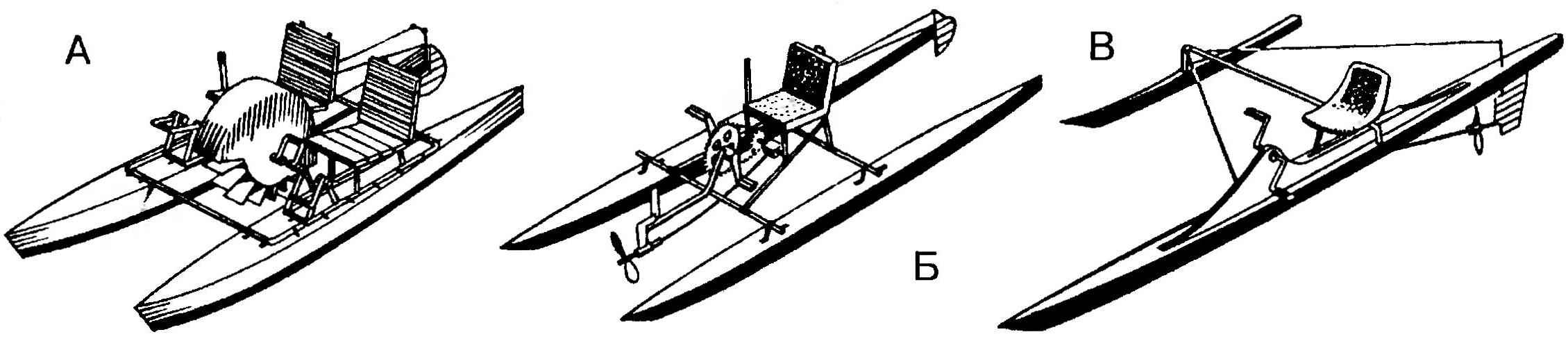
Options vessels muskurahaton:
A — foot catamaran with a paddle wheel;
B — fast foot catamaran with a pulling propeller and stern tube shaft, flexible;
In — speed pedal Proa float-saw;
G — speed muskurahat the underwater hull and hydrofoils, non-static buoyancy;
D — unit hydrofoil and lightweight float chassis for the start and finish.
Further improvement of rowing propulsion is unlikely to lead to any appreciable growth in efficiency. The cyclical action of the oars, slipping it in the water when you stroke, aerodynamic drag at idle (reverse) running, the losses at the entrance of the blade into the water at the beginning of the stroke and exit the water at the end — it all leads to the fact that the efficiency of this propeller is only about 65 percent.
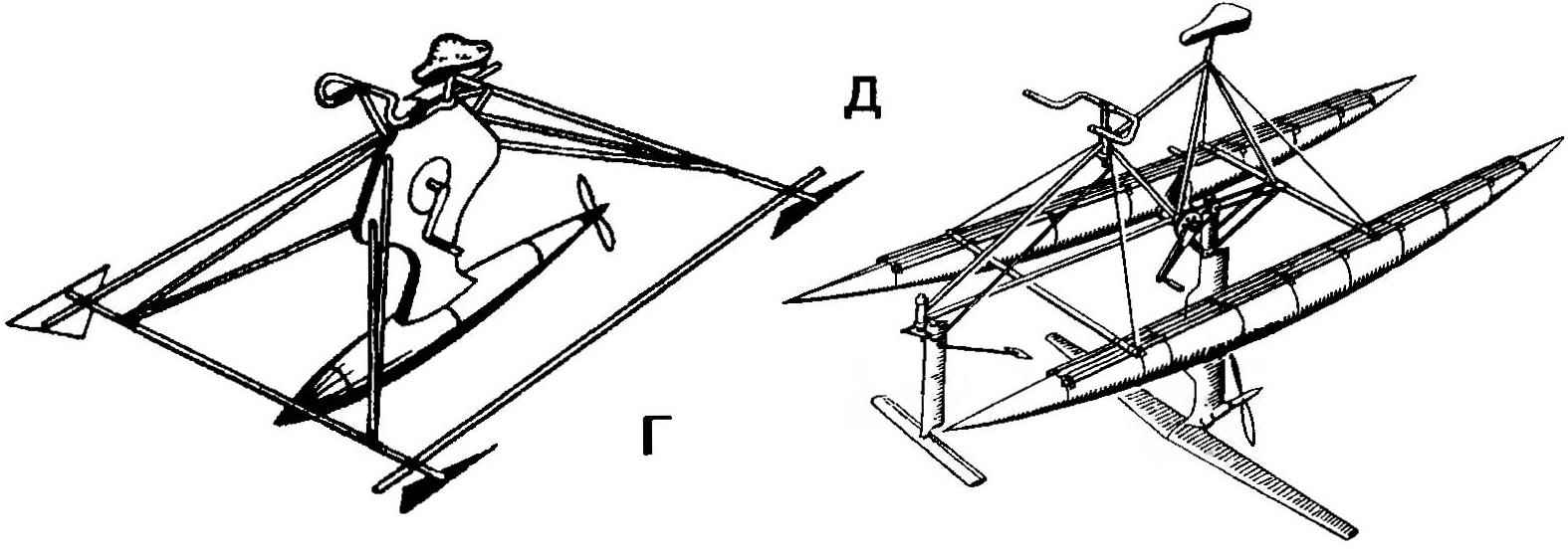
Layout fast aquapad:
1 — front fairing;
2 — the front frame (plywood s10);
3 — sprocket (from a Bicycle);
4 — supporting arm (left only);
5 — seat;
6 — the rear bulkhead of the cockpit (plywood s10);
7 — the drive shaft of the steering gear (dural ski pole);
8 — shaft support;
9 — the lever of a drive of the steering gear;
10 — rudder (plywood s8);
11 propeller variable pitch propeller;
12 — deadwood;
13 — homut fixing seat;
14 — rotary actuator of the steering gear (right only);
15 — multiplier (from a manual two-speed drills);
16 — bracket multiplicator (steel strip 50×5);
17 — beam(steel pipe 30×30);
18 — the case (Vileika of fiberglass and epoxy resin);
19 — driven sprocket (on bike);
20 — the lever of the pedal;
21 — carriage;
22 — traction drive of the steering gear (steel wire Ø5).
Higher efficiency has the propeller. Few people know that rowing screw with a muscular drive in the beginning of the last century were equipped with a conventional rowing boat. The advantages are obvious: he has no recurrence of the stroke, and the so-called focus of the blades during its rotation is constant. In addition, when a relatively small driving power and low speed you can use slow speed propellers of large diameter with narrow lobes — the efficiency of such propulsion up to 90 percent.
When you create a hull with low resistance to motion you need to consider that moving it on the boundary between two media causes a large impedance. To get rid of it is to move the body in one of the environments under water or in the air. In the first case, you will have to create a device consisting of moving under water streamlined float with the propeller and located above it, in the air, seat with foot actuator. The second is to create a pedal boat or vessel on underwater wings. I must say that all these schemes at the time were implemented by the designers, and the most high-speed (hydrofoil) muscularity speeds up to 13 knots!
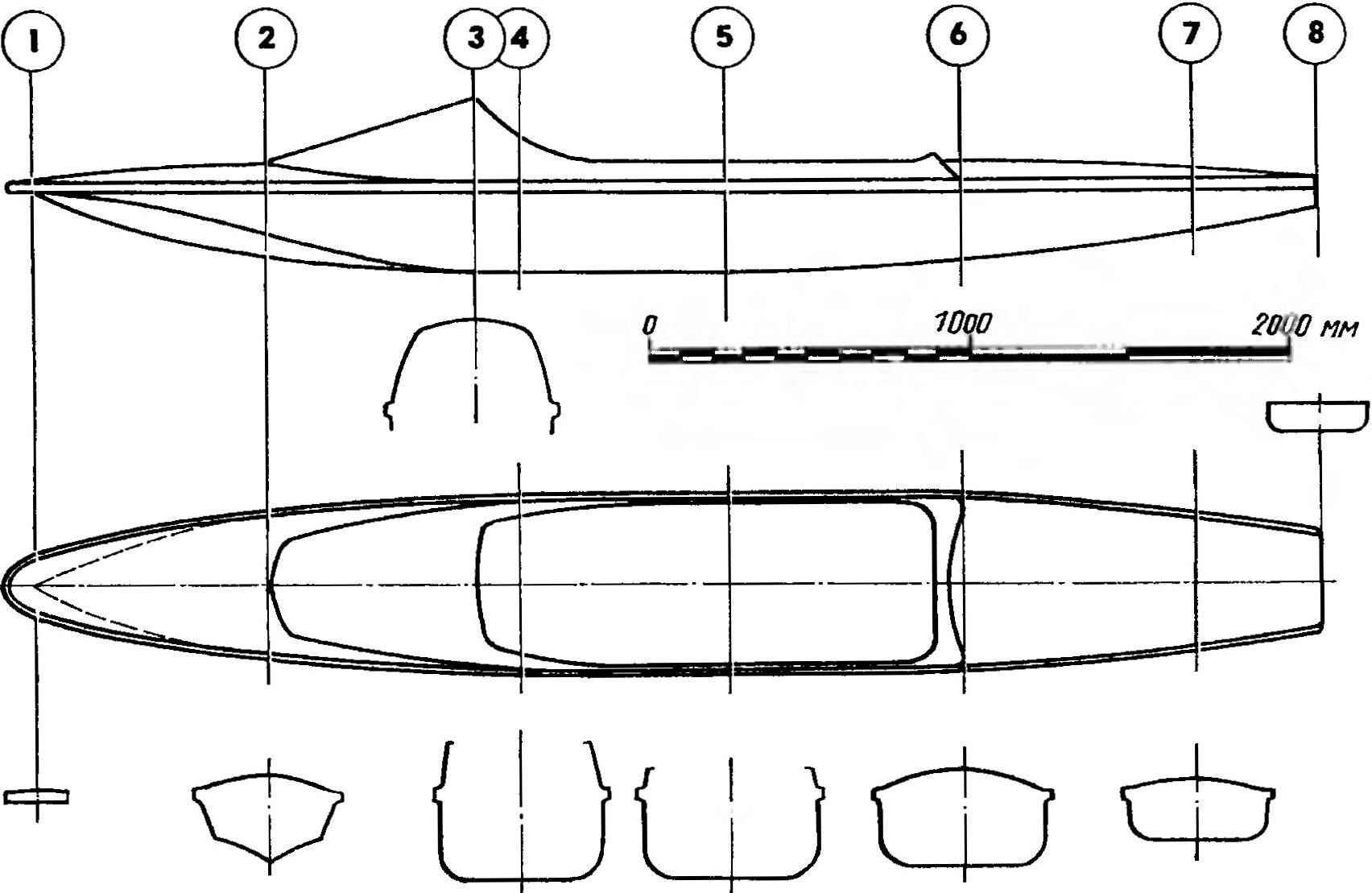
The theoretical drawing of the hull equiped
However, all these record aquapad designed to achieve the highest speed, is unlikely to ever be able to find a practical application. The fact that they have the or poor stability, or lack of tonnage for movement of such apparatus requires special training. Our goal was to create a high-speed musclegod, can be a real water bike, which will almost any person.
Displacement hull aquapad made extremely aerodynamically shaped, with a large length to width ratio. In order that it is so light, it is advisable to make it a method of veclachi on the boob. The boob is the easiest way to make of wood, cement and gypsum.
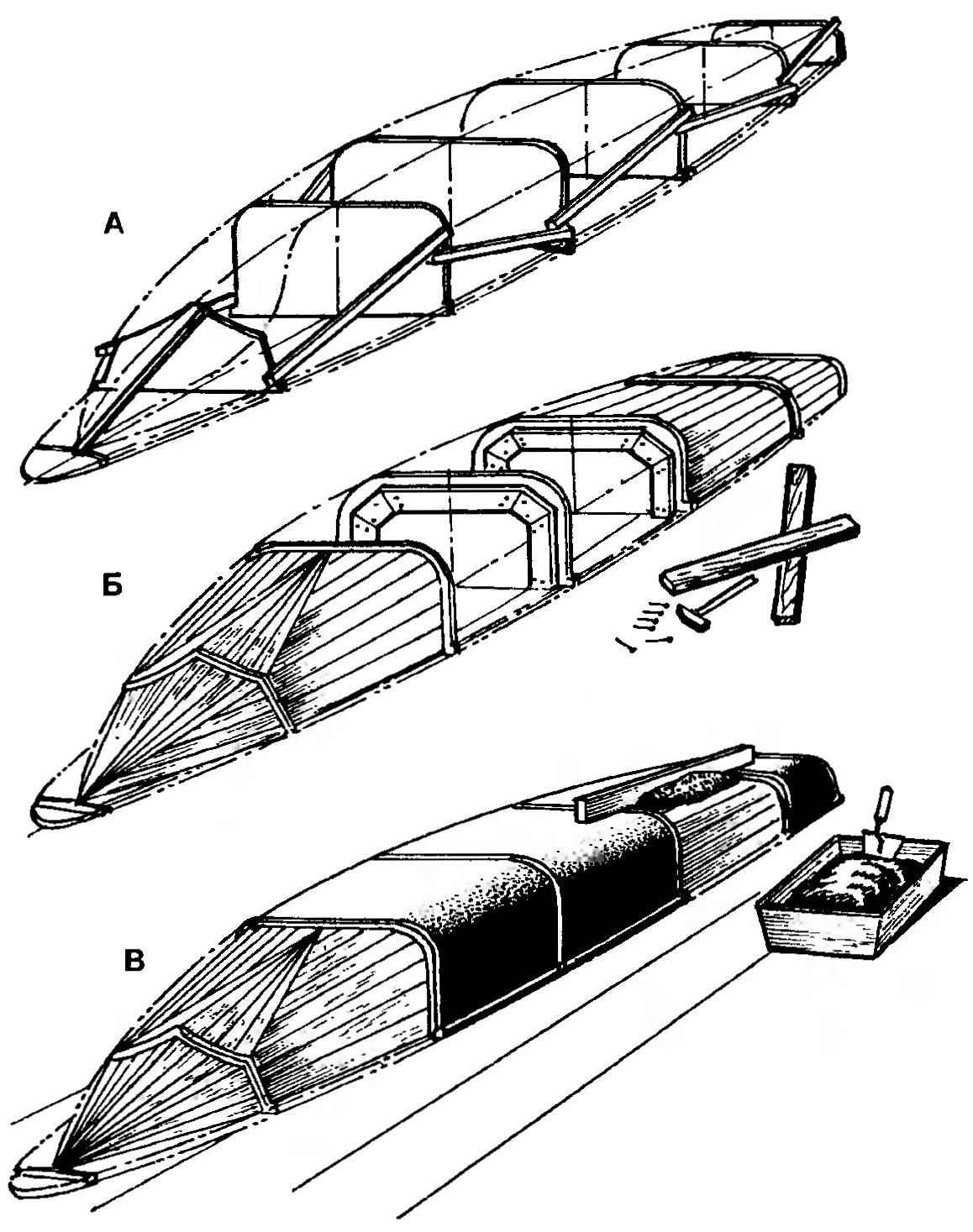
Sequence the manufacture of a dummy case:
A — installation of the frames;
B — installation of wooden cladding;
In applying a layer of cement mortar.
First of all you need to do the base for boob — they can be the plot is flat floor in the barn, or better, a shield of smooth boards: length 4.5 and width 0.7 m. In accordance with the theoretical drawing on the shield is depicted as the axis of symmetry (diametral plane) of the housing and perpendicular thereto — line location frames. The latter are cut out of plywood with a thickness of 6-8 mm; the shield they are temporarily secured by means of brackets, braces.
Further, in each of the frames on both sides are fixed slats — they will be the basis of wood covered boob. Note that the positioning of the strips should be so that the distance from the surface of the wood sheathing to the outer contour of the frame was not less than 10 mm. For covering you can use any scraps of boards, slats or slats of the fence.
Sheathed fool is brought to the desired shape by using cement-sand mortar. The solution was kept on the skin, in plates it is desirable to score more nails to the head of each protrude above the surface for 6 to 8 mm. Solution first pounced on the covering with a trowel and then smoothed with a flat Board, as shown in the figure. The Board must rely on the ends of the plywood frames.
Finally, the dummy is brought to the desired shape with the help of plaster or stucco, and putty. The final stage of work — sanding, staining and coating the surface antiadhesive floors (parquet wax mastic). As a separation layer can also be used food packaging film — it is very thin and literally sticks to any surface.
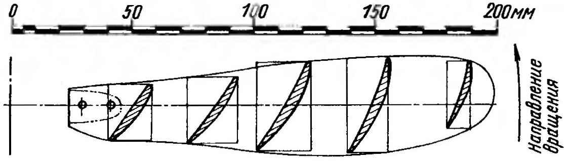
The theoretical drawing of the propeller blade.
For forming the shell of the case will need glass Mat (on two or three primary layers), thinner fiberglass finishing for surface levelling and binder — epoxy or polyester resin. Valaku it is desirable to produce in one step, so that each successive layer of resin and fiberglass fell on the not yet fully cured resin of the previous layer. After vyklicky to the surface of the body, it is desirable to roll the thin plastic wrap — it prevents the volatilization of the epoxy resin curing agent and plasticizer, which accelerates the polymerization, and as a result improves strength and durability of the shell.
A day after the sheath is removed vyklicky boob, and it fit plywood formers that make up the cockpit equiped, fender, Reiki keel and keel, planchonia and stringers. Put them in the housing preferably after the manufacture of deadwood and pedal mechanism.
Upper part of the housing (deck and fairing) is made of plywood thickness of 3 mm; after Assembly it is glued by one layer of fiberglass using epoxy resin.
In the manufacture of housings shall be provided at front and rear parts of the drain holes plugged by a pair of tubes, through which after each use must be drained trapped in the body of water.
The drive of the propeller — pedal, using the standard Cycling of the carriage, the sprocket and a pair of cranks with pedals. Torque from the sprocket is transmitted through roller chain to the multiplier from the hand drill, and then to the stern tube shaft and, in turn, the propeller. The multiplier is desirable to use a two-speed drills — this will allow you to pick the optimal gear ratio chain and gears from pedals to propeller.
Before installing the multiplier, it is desirable to seal his body using the composition “hermesi” or “autoerotic”, and its cavity to fill the transmission fluid — it will increase the durability of the mechanism and efficiency of the gearing. Full containment at the same time, most likely, will not work (the oil will still penetrate to the outside through a clearance in the bearings of the input and output shafts), so the multiplier should be set to a plastic trough to collect the oil.
The carriage of the pedal welded to the beam (steel pipe of square section), which, in turn, was mounted on the front and rear frames of the cockpit. On the beam installed and the seat of aquamedica. As the last-used moulded plastic skeleton of a small office chair, although, in principle, this can be done independently. Mount seat to the beam using a pair of clamps.
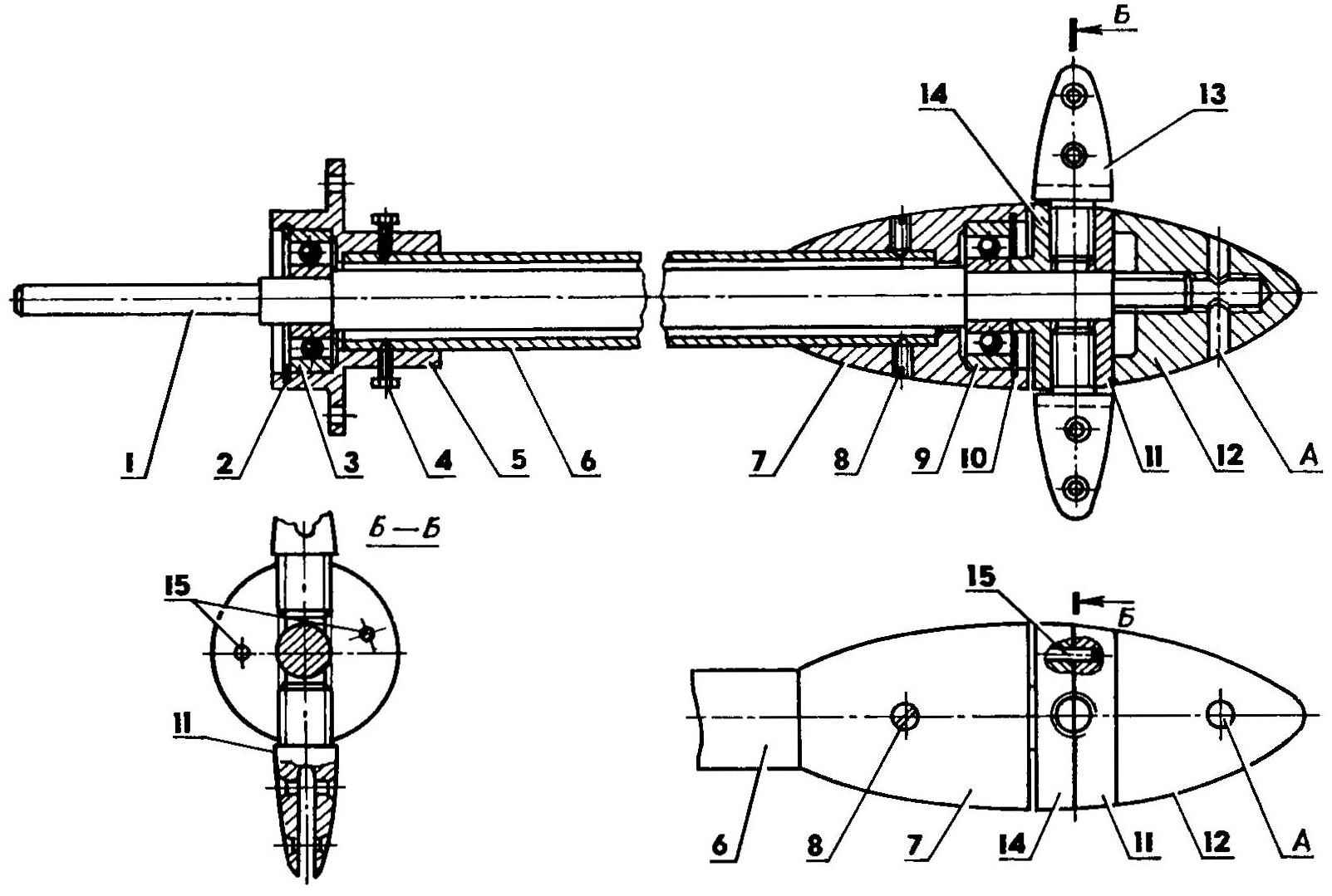
Deadwood Assembly to the hub of the propeller:
1 — stern tube shaft (steel, rod has ø 14-ø);
2,10 — spring persistent ring;
3,9 — ball bearings No. 200;
4 — retainer-front bearing housing (screw M5);
5 — front bearing housing (aluminum, 60);
6 — stern tube (aluminum pipe 20×2);
7 — rear bearing housing (aluminum, Ø40);
8 — pin on the rear bearing housing (screw M5);
11 — support plate fixing device (made of anodized aluminum, Ø40);
12 — Kok (duralumin, Ø40);
13 — the hub of the blade (made of anodized aluminum, Ø20; on the top view are not shown);
14 — plate locking device (aluminum, Ø40); 15 — pins Ø5;
A — hole under the knob.
Deadwood consists of the dural tube with two bearing nodes at its ends — in which revolves a steel shaft. At the rear of the deadwood within the sleeve with locking device, allowing to change the pitch (angle of the blades) in order to achieve optimum efficiency of the propeller and, accordingly, the maximum speed equiped. The bushing is comprised of a dural Coca and double disc clamp, to which are fixed propeller.
The manufacturing of the locking device has one feature that needs to be considered. Before cutting threaded holes M10 under the hub of the propeller between the disks is clamped a circular duralumin plate of thickness 0.5 mm. After drilling and tapping the plate is removed — clearance of 0.5 mm will provide reliable fixation of the hubs in the sleeve.
During Assembly of the deadwood in the cavity between the stern tube and stern tube shaft, you must enter several felt rings, impregnated with grease “ciatim”. It will not allow water to penetrate into the hull equiped at the stern tube.
On aquapage it is most advantageous to use a propeller with a diameter of 400 mm with a narrow blade, cut out of sheet aluminum with a thickness of 4 mm. These screws are most effective when a small transmission capacity and low load on the blade and have an efficiency of over 90 percent! The blank is first bent in accordance with the shape of the concave part of the blade of the screw and twisted, after which the convex part is attached to the profile according to the theoretical drawing of the propeller. The finished blades are fixed on the hubs of the aluminum rivets, and the adjustment of the screw pitch is strictly set at the same angle to the axis of the bushing with the template. The optimum screw pitch is selected in the trial heats.
Recommend to read
 TWO CYLINDERS FOR FOUR WHEELS
To build a simple, unpretentious, and reliable car, I was, one might say, forced by circumstances. Back in the memorable times of general shortages, I bought a well-worn "Zaporozhets" that...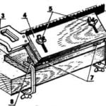 DRANK, SAW!
For the workman man a good tool — it is, as they say, is half the battle. For cutting tools (e.g., saws) it is important that it was sharp. With a significant amount of grinding you have...
