FLYING AT A HEIGHT OF INCHES

FLIGHT TO THE HEIGHT OF CENTIMETERS
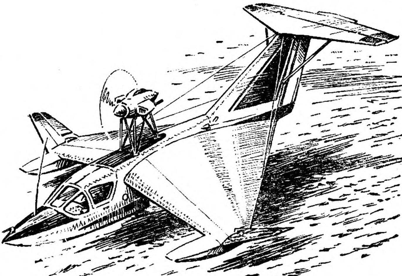
In the Soviet and foreign scientific and popular journals have repeatedly reported Nicoleta apparatus-ekranoplan, including the Soviet pilot the rescue boat amphibious ESKA-1. This car is Amateur-built successfully last cycle of flight tests, designed by Moscow engineers Gramatzki A., E. Grunin, S. Chernyavskaya, Y. Gorbenko and N. Ivanov. Flight tests were conducted by an engineer A. Gramatzki, and then the pilot Baluev A.. ESKA-1 was exhibited on one of the Central exhibitions NTTM was awarded a bronze medal VDNH USSR, and its creators — signs of the winners of the NTTM.

On theoretical foundations colouring mission and design of ESKA-1 says one of its creators, E. Grunin.
 
Ekranolyot history dates back to the mid 30-ies, when built hybrid aircraft, speedboats and apparatus on the air cushion. Its Creator, a Finnish engineer Thomas Cario, and is considered to be the pioneer of economichistory.
 
Design of the first cars, despite the external diversity and the exotic nature of the forms, did not differ refinement study. In those years there existed a coherent theory of the display flight. The projects were created on the basis of a large number of experimental data, and devices, of course, was imperfect. The stumbling block in this period and later, in the late fifties — was the problem of longitudinal stability.
First it is decided the aircraft A. Lippish. In 1964 he built ecranele X-112 and successfully tested it. Later in 1972 saw the release of another apparatus — X-113А. Made of fiberglass, he showed excellent flight characteristics and made up of aerodynamic quality equal to 30!
 
What is ecranele? In fact, it is a seaplane with a modified wing. Aerodynamic configuration allows it to fly as far or close from the screen, the ground or water. surface, figure 3 shows a classic growth curve the aerodynamic qualities of the device by reducing the relative height of the flight. A noticeable effect of the screen on the characteristics of the wing manifests itself at altitudes smaller than the length of the mean aerodynamic chord (SAH). Here is a different picture of the flow than when moving off screen. With a very small distance to it, measured in inches, the pressure increase under the wing close to the value of dynamic pressure and lift force increases sharply due to the pressure in the locked thread. Two-dimensional flow profile shown in figures 5 and 6. The physics of the phenomenon is clear: away from the lifting force is formed mainly at the expense of rarefaction over the wing, and near — by increasing the pressure under it.
 
Fig. 1. The control circuit ekranolyot.
 
Fig. 1. The control circuit ekranolyot.
 
Figure 2. The layout and components ukranalit
 
Figure 2. The layout and components Kranolta:
 
1 — handle, 2 — pedal, 3-battery 4 — receiver air pressure, 5 — pin antenna, 6 — removable part of the lantern, 7 — compartment of equipment 8 — fire extinguisher, 9 — rotor, 10 — engine 11 — engine, 12 — motor, 13 — pull Elevator control, 14 — removable hatches for the approach to transaction management, 15 Kil, 16 stabilizer, 17 — Elevator 18 — rudder, 19 — water wheel 20 — tank 21 — seat pilot and the passenger, 22 — dashboard, 23 — handle engine control (Gaza strip), scheina b — B, B — C, d-G, D-D, E-F, g — F and the ribs of the wing is increased.

 
From the graph, which in aerodynamics is called the polar line, is seen as the proximity to the screen affects the lifting force and frontal resistance (Fig. 7). With a decrease in the relative altitude increases, the su and reduced CX. Is a cool polars shift up and to the left. She receives a less pronounced maximum as flow separation on the upper contour of the profile has less influence on the magnitude of the lift force. This leads to a significant increase in the aerodynamic qualities of the entire apparatus. From ESKA-1 it is, for example, reached 25.
 
It’s more complicated with stability and controllability. For flight conditions these parameters ekranolyot studied is still weak, especially when changing the mode of movement or elevation change, they usually change dramatically.
 
Consider how behaves ecranele in screen mode. Suppose it moves a few inches above the water. The flow pattern of the wing the air; the pressure under the wing increases, begins to operate the on-screen effect quality increases. But for that you have to pay dearly: at speeds over 200 km/h ecranele suddenly loses stability and flips over the stern, so died in 1967 Donald Campbell Bluebird and seven years later, Cesare Scotti on the tunnel boat.
 
What happened? The solution was found: change the wrap of the wing entailed a deterioration in longitudinal stability. Aerodynamic focus Kranolta, continuous in-flight at altitude, the screen suddenly split, and each of its “halves” began to wander along the chord of the wing and behave differently: one was to track the angle of attack, the other fell into dependence on the distance to the water. Called them: the most “wayward” — focus on height, the other focus on the angle of attack.
 
“Wayward” here’s why. If a conventional rectangular wing with aspect ratio of 0.5—2 implement end-planes-washers (so it does not leak air) and to bring to the screen flow of the wind tunnel, the focus height will shift along the chord ago. The relative height of the wing above the screen, equal to 5-6% of SAH, it will stop and begin to return. Focus also on the angle of attack has a more permanent character and a decrease in the height only goes one direction — back from the toe of the profile to its middle. To understand the pattern of run-up tricks experimenters explored the different types of wings. It turned out that the presence of the screen, the degree of run-out is directly dependent on the wing shape in the plan. Of these, only one (!) has a minimum takeoff run is a Delta wing with trailing edge reverse sweep 45-60° and an elongation of 1.7— 2. Moreover, owing to the geometric shape of the wing the focus height is placed in front of the focus on the angle of attack. And this is the main condition for longitudinal stability in flight above the screen! Figure 4 shows the position of the major aerodynamic forces acting on ecranele.
The criteria of its pitch stability are: the stability margin in height, i.e. the distance in fractions of a SAH from the center of gravity Kranolta to focus in which is applied the increment of the lift force caused by changes in altitude, and the stability margin of the angle of attack is the distance from the DH to focus the angle of attack.
 
Ecranele to fly, and the pilot wasn’t afraid to roll over on it, you need a selection of aerodynamic configuration to achieve focus position at the height of the front focus angle of attack, which in the mathematical calculation is expressed as the inequality:
 
ХFN — ХFα < 0.
 
If some force, such as a gust of wind will press ecranele to the water, the increment of the lift force in the focus height relative to the center of gravity creates a negative pitching moment. The angle of attack from positive will become negative. Then focus on the angle of attack will be a negative increment, will cause careerwise time, restoring equilibrium. And nothing bad will happen.
 
COMPROMISE — ALLY DESIGNER
 
Ecranele should be easy and at the same time durable, easy to manufacture, reliable in operation. Finally, it needs to be cheap.
 
Given these sometimes conflicting requirements, we analyzed a number of possible designs and came to the conclusion that the most simple is a wooden unit with wide application aviation plywood, and foam core, fiberglass and other materials.
 
For the wing ESKA-1 came modified profile TSAGI R-11-CLARK y with a flat bottom rim. It is well established in the investigated models. The wing has aerodynamic and geometric twist, relative thickness of profile in the wing root 10%, at the end of 12.5%, and the angle of deviation of the profile from horizontal Kranolta from the root to the end of the console is reduced from 4.5 to 2.5°.
 
The wing in plan is triangular. The centre of gravity position for various angles of attack and if you change distance to the screen varies slightly. For lateral stability and handling on consoles are the so-called outer wing (PTS) — airfoils equipped with ailerons.
 
Interesting fact: many for aerodynamic have a rectangular wing of small aspect ratio. It although easy to manufacture, but has two major drawbacks. First, the position of the center of pressure it depends on the angle of attack and distance from the water and ranges from 15-65% of the mean aerodynamic chord. Second, the flow around such a wing with end vertical planes-washers formed air vortices that increase resistance to movement and significantly reduce aerodynamic quality. For this reason, we from direct wing refused.
 
Horizontal tail. When designing consider the following: tail mounted behind the wing of small aspect ratio, is ineffective when the apparatus of the zone of influence of screen — increase the bevel of the flow behind the wing leads to the fact that ecranele is trimmed at high angles of attack, and the plumage is in an unfavorable flow conditions. We installed it on the end of the keel — wing most remote from the place where you can not be afraid of the bevel flow. The dimensions of the tail are selected such that the longitudinal static stability allowed ekranolyot to fly and have the screen on top.
 
R and p. 3. The dependence of the aerodynamic qualities from the relative height of the flight.
 
Fig. 3. The dependence of the aerodynamic qualities from the relative altitude.

 
Fig. 4. Forces acting in flight over water.
 
Fig. 4. Forces acting in flight over water.
 
Fig. 5. The wing's flow over the screen.
 
Fig. 5. The wing’s flow over the screen.
 
As the ESKA-1, starts with water, then it has to have floats and a planing surface of the hull of the boat. This is the most important part of any Kranolta, with their help, he speeds necessary for the separation from water.
 
During the run, the flow resistance is growing rapidly, then the lift of the wing becomes equal to the weight of the device, its resistance decreases and it separates from the water. From ESKA-1 maximum resistance of about 70 kgf — was celebrated at a speed of 20-25 km/h (Fig. 6).
 
Another feature of the hydrodynamic layout ESKA-1 — afloat the entire rear edge of the wing immersed in shallow water and at speed 40— 50 km/h it acts as ridanna surface. Big wave resistance is not generated, and the stroke of the apparatus is smooth, since the wing is based on a lot of scallops waves. When the speed of separation ecranele touches the water only by redan hull and the wing is experiencing shock loads…
 
So, by way of trade-offs and design tweaks, we engineered our car. But this approach to the design paid off: four years of operation have confirmed a judicious combination of ideas inherent in its design.
 
THE DESIGN OF THE ESKA-1
 
The fuselage Kranolta — boat. It includes: cabin crew, instrumentation equipment, fuel. Outside attached wings, an engine with a propeller and keel of a horizontal tail.
 
The main in the boat — frame, assembled from frames and stringers. Frames 15, they are made of pine slats connected by bosses of lime and brackets from plywood. Frames No. 4, 7, 9, 12 and 15 power. The most loaded, perhaps ninth: it is docked wing, and the lower part is a ledge of redan.
 
Pine stringers: 4 — section 20 X 20 mm and 12 — 16 X 10 mm. from the Bottom of the fuselage where the sides joined the bottom, are two bilge stringers made of beech section 20 X 20 mm.
An important element of the power set — box-shaped keel, located ka the bottom of the boat along the axis of symmetry. The keel is formed by two shelves (upper and lower), connected by walls made of plywood with a thickness of 2 mm. flange Width: 20 mm, thickness — variable: bow shelves, it is equal to 12 mm, in the area of Rodan — 20 mm. throughout the length of its keel plywood walls supported by struts.
 
The housing is encased aircraft plywood with different thickness in the nose — two mm, then the thickness gradually increases and the area of redan is 7 mm. the expediency of such gain we have seen after a collision with a floating snag. Less” durable plating would not survive.
 
Ha boards — plywood with a thickness of 2 mm, the fairing is 1 mm. the Outside of the entire boat covered with a layer of fiberglass stamps of ASTT(b)With epoxy resin. To keep the boat’ kicking the water and had a clean smooth surface, which is important for its wrapping, sheathing stripped, treated by epoxy putty and painted with synthetic enamel and then covered with a layer of parquet lacquer.
Bolshej of the equipment and devices Kranolta placed and the bow of the boat: tow hook, PA — Pitot TP-156 (for measuring speed and altitude), an antenna pole of radio battery.
 
In the middle of the boat cockpit. In it one behind the other aircraft has two seats with seatbelts and niches for parachutes. The rear seat is located near the center of gravity Kranolta to alignment machines less dependent on the passenger. The floor in the cabin is made of polyethylene sheet, placed him under transaction control the ailerons, elevators and turning. To the left of the pilot’s seat on the panel there is a handle engine control (Gaza strip) and the block electrotumbao. In the cockpit, on the bulkhead No. 4, mounted instrument panel with indicators of speed, altitude, turn and slip, as well as a variometer, compass, artificial horizon, tachometer, ammeter, voltmeter, and temperature of the cylinder heads of the engine. The cockpit is transparent canopy. The front part is fixedly mounted on the fuselage, rear — removable. Castles of the flashlight make it easy to access the cockpit. In an emergency you can ecranele bistro to leave, dropping the lantern.
 
To the frame number 10 on a special cradle suspended fuel tank. He is drawn to the lodgement metal strips, lined with felt. The points of fastening of the keel and auxiliary wing spars are mounted not frame № 15.
 
For ease of transportation and repair Kranolta his wing is made up of two consoles, connected to the boat with bolts M10. Front and rear docking units — mounts made of steel 30KHGSA. They are connected with the flanges of the side members with M5 bolts and are designed as the same wing, ka fourfold overload with a safety factor of 1.5, i.e. total margin of safety equal to 6. This supply is sufficient for normal operation of the apparatus.
 
The console is odnaleziono design with rear auxiliary wall, stringers, four to nine ribs.
 
Fig. 6. Dependence have thrust and aerodynamic drag from the speed of flight
 
Fig. 6. Dependence have thrust and aerodynamic drag from the speed of flight:
 
A — the aerodynamic drag, G is the flow resistance, C — total, T is the available thrust, And excess thrust; and — navigation mode, b — plane, in — overcoming “hump” of resistance, g is the separation from water, d — flight.

 
Fig. 7. The polar ESKA-1 at different heights.
 
Fig. 7. The polar ESKA-1 at different heights.
 
Fig. 8. The pressure distribution on the wing profile.
 
Fig. 8. The pressure distribution on the airfoil.
 
The main spar consists of two shelves, walls and diaphragms. Top shelf has a thickness 34 mm at the root and 18 mm at the end of the spar, the lower — respectively 25 and 18 mm flange Width 38 mm across the span. Glued shelves from a set of pine slats with epoxy resin in a special clamping bench. The walls of the spar on the plywood VS-1 with a thickness of 1.5 mm. And for the strength of the fibers of the outer layers of plywood are oriented at an angle of 45° to the axis of the spar. The diaphragm is made of pine planks 34X8 mm cross section, glued to the shelves with the corners of Linden. The construction height of the spar along the span is determined by the thickness of the airfoil.
 
Rib number 1, 2, 3, 4, and 5 – truss and truss-beam construction, pine shelves and diagonals, tied together with plywood gussets. Rib No. 1 — power, continuous, it is located on the attachment points of the wing. Rib No. 6, 7, 8 and 9 — beam construction, with shelves made of pine and the walls out of plywood with a thickness of 1.5 mm.
 
An auxiliary rear spar similar to’ core. His troops — a constant width of 32 mm. the thickness of the upper shelves to the root of the spar 20 mm, on the end is 12 mm; the thickness of the lower — respectively 15 and 10 mm. on both sides of the spar sheathed mm aircraft plywood.
 
SUNGLASSES perched on the end of the console at an angle thereto. Under the plywood sheathing there are two spar, bow stringer and six ribs. The front longitudinal box section with shelves 25 X 12 mm and a wall made of plywood with a thickness of 1 mm. of the Rear spar-channel with the same shelves and the wall.
 
Aileron plane type consists of a spar, front, rear stringers and five girder ribs. Spar-channel shelves 15X10 mm and the plywood wall of thickness of 1 mm To the spar glued pine boss to install the hardpoints of the Aileron.
 
The internal cavity of the wing is double-coated with linseed oil. Wing SUNGLASSES and ailerons on the outside covered with cloth AST-100 covered with four layers of lacquer NC-551 and painted with white alkyd paint.
 
Resistance to water ekranolyot attach the floats from foam PVC 1. Omi covered with a layer of fiberglass of astg(b), and attached with M5 bolts to the wing not four ears of steel 30KHGSA.
 
Tail — keel with rudder and a water rudder and stabilizer with rudder heights. Keel sheathed millimeter plywood and is a conventional design of the two side members, eight ribs and a sock. The rear spar-channel with pine shelves 28X14 mm and the wall of the ka of plywood with a thickness of 1.5 mm. the Front spar of the same type as the rear, only the shelf of his less — 14X34 mm. To reduce malkivka socks keel broken ribs and form with the front edge of the keel is almost straight angle.
 
The rudder consists of plywood covered with a sock, spar, stringer and tail thirteen ribs. The steering wheel with a cloth AST-100, and suspended to the keel at two points.
 
Stabilizer in plan trapezoidal profile symmetrical NASA-0009, uGod installation plus 5° from horizontal Kranolta. The frame of the stabilizer is assembled from longitudinal support walls of the front stringer and 13 ribs. The stabilizer is bolted on four ears of the keel. The nose of the stabilizer is sewn plywood BS-1 with a thickness of 1 mm.
 
Stabilizer spar box section on pine wolves 20X12 mm and walls of mm plywood. On the spar there are two eyelets for fastening the struts from aluminum tubing teardrop-shaped cross-section. Pipe stiffen the combination of “Kiel — stabilizer”.
 
The Elevator is the same the wheel turns; attached to the stabilizer at three points. The rudder and stabilizer covered with a cloth AST-100, covered with paint and dope.
 
Rotor installation includes a two-cylinder four-stroke carburetor motorcycle engine M-63 output of 32 HP, special step-down gear reducer with a gear ratio of 1 : 2,3, hardwood SDV propeller-2 fixed pitch, Ø1,6 m and motor frame made of steel tubes Ø 26 mm.
 
The engine is attached to Motorama the M8 bolts through the rubber dampers and is mounted behind the cockpit on the nodes of the power frames No. 9 and 12. The maximum power the engine develops 4700 rpm gear propeller gets 1900-2100 rpm This corresponds to 95-100 kgf thrust.
 
The launch of the propeller installation is performed by the starter ST-4. It is installed on the engine through the gears and it rotates the camshaft. The power source of the electric starter is the battery ITSELF-28 with a voltage of 12 V. To ignition system worked reliably, the engine is equipped with magnetos “KATEK” driven by the camshaft via an intermediate shaft extension.
 
Standard carburetors did not satisfy us with its inconsistent, especially when sudden changes in engine operating conditions. We replaced it with a single carb “Weber-32 JEM”.
 
As you can see, the design of the ESKA-1, in principle, simple. Dominated by wood, plywood, fabric. The metal parts are kept to a minimum, and their production are not scarce steel grades and alloys. Externally ecranele is also quite simple, complex, curved surfaces little. Therefore, we believe ESKA-1 is easy to reproduce for those who intend to build ecranele on the basis of just such a wooden structure.
 
TECHNICAL DATA KRANOLTA ESKA-1FLIGHT TO THE HEIGHT OF CENTIMETERS
 
Scale, m……………6,9
Length, m……………7,8
Height, …………….2,2
Root chord of wing, meters……..4,11
Lines length, m………..1,0
The narrowing of the wing …………4,11
Elongation …………..1,996
The average aerodynamic chord (SAKH), m . 2,873
Wing area, m2……….13,15
Total bearing area, m2……13,39
The area of the horizontal tail, m?. . . 3,0
The area of the vertical stabilizer, m; . . . . 3,6
Mass of structure, kg …….234
Full flight weight, kg……..450
Wing loading, kg/m2………39,5
Engine power, HP……….32

Recommend to read

  • BREAKTHROUGH LEADERSBREAKTHROUGH LEADERS
    Golf car class, OPEL ASTRA. Competition has always been considered the engine of progress, including in the automotive industry. Vehicle manufacturers all by hook or by crook tried to...
  • UMBRELLA VICE VERSAUMBRELLA VICE VERSA
    Not everyone is a fan of tinkering, living in the city, has for its classes a special room. Often we have to settle for a table in the kitchen room. In these circumstances it is...