
 SMALL SPOOL, BUT PRECIOUS!
 Among multipurpose internal combustion engines, created by our readers, still have not found structures with the spool naturally. Meanwhile, this scheme has proven itself quite well and is often used in power installations of various applications. Under this scheme, for example, in the prewar years in the USSR mass-produced outboard motors LM-7 “Rubinar” and LM-6, which enjoyed great popularity. Known successful attempts of application of the valve timing in the engines of sports motorcycles and model the micro-engines of various applications.
There is quite natural question: and what are the benefits of valve of the gas distribution compared with the crank-chamber? First, the spool allows improved filling of the cylinder with the working mixture; second, the use of the valve allows to simplify the design and manufacture of the cylinder (suction channel becomes unnecessary, because a combustible mixture is supplied directly into the crankcase after it created the necessary vacuum); third, the use of the valve increases the efficiency of the engine, preventing the release of fuel into the atmosphere from the suction pipe of the carburetor.
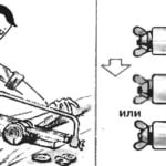
Figure 1 gives a General overview of slide valve systems used in two-stroke gasoline engines of small volumes (1.5— 500 cm3). Each of these systems has its advantages and disadvantages. Suction through the hollow neck, Kalanchoe shaft (Fig. 1 A) requires a significant increase in its outer diameter to provide the necessary area of the flow section of the suction channel, without weakening the strength of the shaft. Accordingly, increasing the diameter of the support core of the neck, increased friction losses. However, this system has undeniable advantages: possibility of application of the carburettor with a falling stream of the mixture is placed directly above the suction hole of the spool that allows you to install the custom length intake pipe between the carburetor and the spool (Fig. 2), and the ability to change timing on a running engine by setting the rotary holder over the suction hole of the spool (Fig. 3).
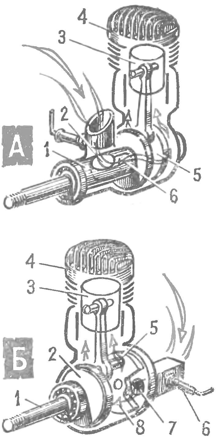
Fig. 1. Typical schemes directional spool valve-timing. (Conventionally shown single-cylinder engine.) A suction through the hollow neck of a cranked shaft:
1 — core front neck, 2 — suction port, 3 — piston, 4 — cylinder, 5 — pin, 6 — a hole in the cheek of the crank; B — suction through the rear cover of the crankcase disc valve: 1 — crankshaft 2 — cheek of the crank, 3 — piston, 4 — cylinder, 5 — finger of the crank, the rotating spool, 6 — needle jet 7 — and suction port in the cover housing, 8 — disc valve.
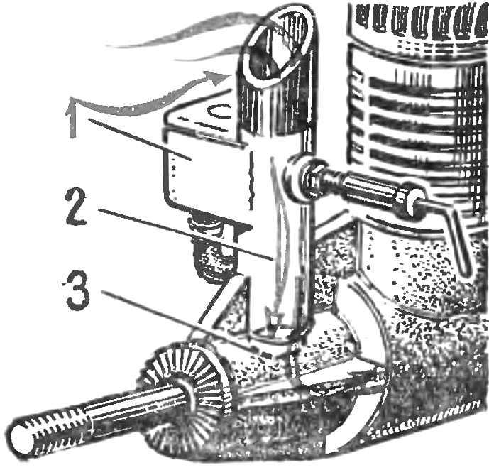
Fig. 2. Tuned length intake tract:
1 — carburetor, 2 — elongated suction nozzle, 3 — suction port of the hollow crankshaft journal.
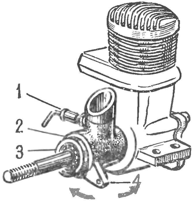
Fig. 3. Swivel clip to change the camshaft timing on a running engine:
1 — needle jet, 2 — swivel clip with built-in nozzles, 3 — ball bearing, 4 — pivot arm.
Another system of the suction — via hole in rear cover of a casing, a disk valve overlap (Fig. 1 B), is structurally simpler and allows you completely get rid of the slide bearings, setting the shaft on ball bearings. Disk valves are made of materials that are inhomogeneous with the material of the crankcase, to reduce friction losses (steel, plastic).
The engine with which we will introduce you today, designed by engineer A. Gerashchenko. As can be seen from figure 4, the two cylinders positioned opposed at a 180° angle to each other in common to both cranks Carter. This scheme got the name “boxer” and is currently used widely, especially for four-stroke engines. Two-stroke engines of the type “boxer” are less common, but legitimate or not — hard to say. Experience L. Komarov, A. Nikitin, and Beloshapkina, V. Buyanova and other Amateur designers who created and successfully operating two-stroke engines of this scheme, says that to abandon it, especially in the practice of Amateur engineering, you should not.
Posting description engine design engineer A. Gerashchenko, we hope it will appeal to many and pass the practical test, being built by the designers-lovers.
MULTI-PURPOSE “BOXER”
Engine AG-2 — two-cylinder, two-stroke, opposed, with simultaneous working cycles in opposite cylinders. Heads and cylinders — shirts air cooling. Pistons and rods can be used from a motorcycle engine M-106 or IZH-th-3. In the first case, the total working volume of 250 cm3 and a power of about 20 HP; in the second, respectively 350 cm3 and about 25-30 HP, depending on the degree of force and use of fuel. The variant of the installation of the new cylinder from the motorcycle IZH (Planeta Sport) with the manufacture of the corresponding crankcase and crankshaft. In this case, when the total working volume of 700 cm3 can be achieved with a power of 60 HP.
Engine crankshaft AG-2 to obtain the minimum weight of the assembled parts of the motorcycle “Jupiter-3”, the last a small additional processing: with right-hand axle shafts of the crankshaft dismantled middle the cheek; on the left is cut intermediate root neck, and drilled the pin hole of the connecting rod, with the corresponding machining plane intermediate the cheeks. After that, the finger of the cheeks (from the generator) is pressed on the connecting rod and machined middle hole cheeks of the crankshaft. On the cheek side of the sprocket ring is removed chamfer 9X45°; the same side zapressovyvajutsja 4 fingers 0 6X10 mm for mounting the disk spool. In a radical neck from the generator on the M7 thread screwed additional transition taper (taper of 1 : 5) under makovicka maggino from scooter “Vyatka”.
Balancing the crankshaft may be accomplished through perforations in the cheeks, which are recommended at the end of this operation to drown out the cork or foam inserts on epoxy glue. The engine crankcase (Fig. 6) is executed without internal partitions, whereby a minimum length and a much smaller weight compared to the crankcases for two-cylinder engines, which require separate sections for each crank.
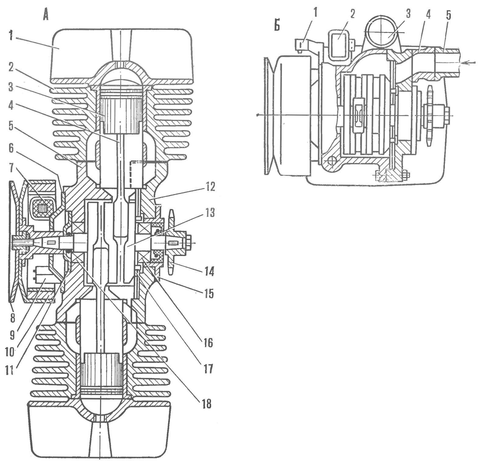
Fig. 4. Layout engine AG-2:
A — horizontal incision: 1 — cylinder, 2 — cylinder, 3 — piston, 4 — rod, 5 — the case of Carter, a 6 — base maggino, 7 — coil power ignition, 8 — the drive for manual start by cord, 9 — block diodes, electronic ignition, 10 — flywheel maggino, 11 cover seal 12 — case cover, 13 — crankshaft, 14 — sprocket chain transmission, 15 — Cup, 16 — roller bearing No. 42205, 17 — disc spool, 18 — bearing number 205; B — vertical incision: 1 — inductive sensor, 2 — thyristor unit, 3 — two-spark ignition coil, 4 — intermediate reducer, 5 — nozzle carburetor.
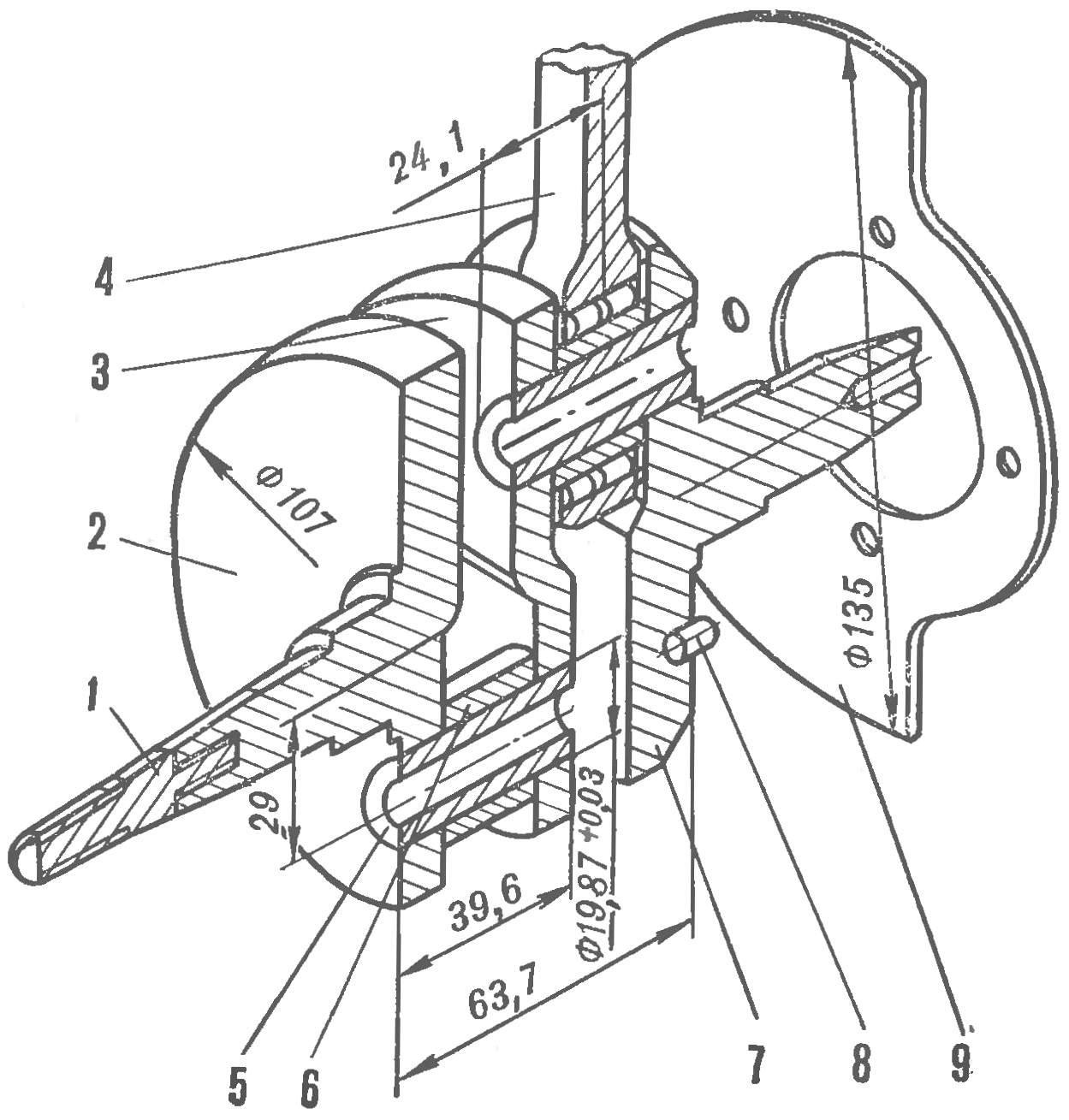
Fig. 5. The crankshaft Assembly with the spool:
1 — transition cone under the flywheel maggino; 2 — cheek crankshaft (IZH-Yu, right); 3 — average cheek of the crankshaft; 4 — connecting rod roller bearing from IZH-th; 5 — finger rod from IZH-Yu; 6 — a nut from a IZH-th; 7 — crankshaft cheek (from IZH-Y. left); 8—finger spool Ø 6X10 mm (4 PCs); 9 — disk spool.
The crankcase AG-2 is technologically very simple — it consists of a housing and cover, is not axial, a radial connector, which greatly facilitates its mechanical processing and subsequent Assembly of the engine. The body and cap of the crankcase cast on the wooden models in earthen or shell in the form of alloys AL-9, AL-5, etc. followed by heat treatment.
As mentioned above, the inlet mixture in the crank chamber controls the valve disk of spring steel of a thickness not exceeding 0.5 mm. it is Possible to manufacture it from plastic. With one side of the disc cut in order to open the dump window. Spool freely planted on four fingers Ø 6 mm, pressed into the cheek of the crankshaft, and has the ability to navigate through them in the axial direction under the influence of pressure fluctuations within the crank chamber. But this movement is limited by the clearance of 0.5 mm between the butt cheeks of the crankshaft and the inner surface of the case cap, with the outer side of which is attached through a reducer carburetor from a motorcycle “IZH-Planeta”.
When installing the valve inlet ports in the cylinders jammed the cork or foam tabs on epoxy glue. The use of a disc valve on the engine AG-2 gave the possibility to extend the duration of intake of the combustible mixture; to obtain an unsymmetric timing; to introduce an additional (third) vent the cooling channel of the piston. Taken together, this improves the filling of the crank chamber with fresh mixture and therefore, increases the engine power. In addition, the disc valve will provide a selection of the best phases of intake as the beginning and duration (by changing the configuration or disk replacement), reduce the gas-dynamic resistance of the intake tract by reducing its length and turns.
A feature of the engine of AG-2 — application of electronic ignition systems, using parts of electrical equipment “Vyatka-Electron”. For installation of this system, you must purchase the base maggino flywheel, flywheel, thyristor unit from “Vyatka-Electron” and doohickery the ignition coil of type B-11 or B-201.
As is known, conventional ignition system can operate reliably only in the range of 7 thousand rpm of the crankshaft, allowing the current at the breaker contacts no more than 5 And, respectively, the voltage on the plugs to 12 thousand. the Electronic ignition system provides normal spark over a wider range, up to 10-12 thousand rpm, the crankshaft, the current in the primary circuit of the ignition coil 25 A voltage candles up to 16 thousand.
Used thyristor contactless system does not have the usual Cam and mechanism of the interrupter with a capacitor, that is, moving parts and contacts subject to wear. So the value of the ignition timing is almost constant.
Electronic ignition system is less sensitive to moisture and contamination of the candle, since the energy for spark is stored in the capacitor, not the coil, thereby reducing the time of breakdown of the spark gap in the spark plug. Describes the advantages of the electronic system make it indispensable for engines of the Amateur design, power density and specific gravity which, as a rule, very high requirements.
Consider the work of proposed system: the flywheel maggino (Fig. 7B) made a window where is displayed the end of one pole Shoe, and the node breaker replaced with an induction sensor 2. When you rotate the flywheel with the magnet in the coil (Fig. 8) is excited by the current through the circuit: diode D1 — capacitor With the primary winding of the ignition coil — housing — charged capacitor to a voltage of 200-250 per revolution of the crankshaft. A thyristor and a diode D3 connected to this circuit, that period of “closed”. When the protrusion of the pole Shoe passes under the poles of the MAG-nieprawda sensor, its coil is excited by the voltage pulse 6— 7 V. half wave Negative pulse is shunted by diode D2, creates a positive current in the control circuit of the thyristor. The last “open” and forms a circuit for discharging the capacitor through the primary winding of the ignition coil. This discharge excites the secondary winding 5 doohickery ignition coil high current, up to 15 thousand, which is supplied to the spark plugs. Diode D3 maintains the oscillatory process in the system and protects the thyristor from reverse voltage.
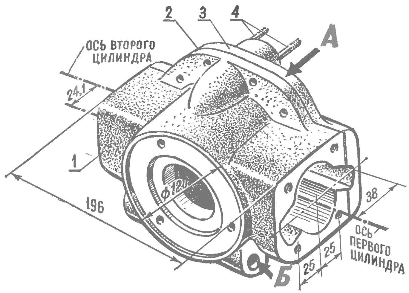
Fig. 6. Case Assembly with cover:
1 — housing; 2 — gasket; 3 — case cover; 4 — stud mount the reducer with the carburetor; A — line radial casing with a cover; B — the rush for the M10 engine mounts to Motorama.
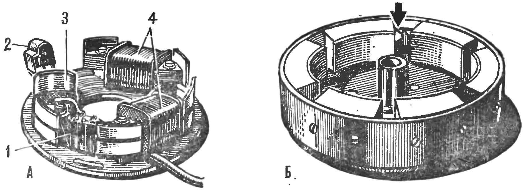
Fig. 7. Details of electronic ignition system:
A — base flywheel maggino: 1 — diode units, 2 — induction sensor, 3 — coil with windings of the supply capacitor and charging battery, a 4 — coil lighting; B — flywheel maggino (the arrow shows the projection of the pole Shoe and the window in the flywheel).

Fig. 8. Schematic diagram of electronic ignition:
1 — coil recharging batteries; 2 — winding power; 3 — winding of the induction sensor; 4 — electronic block; 5 — duhoka-Wai ignition coil; 6 — lighting coil; 7 — wire to the lighting devices; 8 — wire for recharging the battery; 9 — the ignition switch; 10 — ignition plug; D1, D3 — unit CD 205Ж; D2, D4 — block CD 205Д; thyristor — КУ201К; C — capacitor 4 µf, 400 V.
Thyristor unit and ignition coil strapped to the top of the crankcase. The ignition timing adjust by turning the base maggino so that the claw magnetic poles of the flywheel will overlap by 1/z—3/4 the thickness of the first during the rotation of the end of the magnetic sensor. On the basis of maggino have leads for connection of lighting devices 7 and recharging the batteries (voltage 6 V) via a diode D4.
Possible to install conventional, makovicky ignition system, with one circuit breaker and doohickery coil (or two coils odnoskatnyj). Details for such a system will approach from scooter “Vyatka” or from the boat motor “Breeze”.
For manual engine start (cord) on the flywheel with three screws is attached to the disc with the grooves. In the case of engine AG-2 to drive the propeller (for example, snowmobiles, microplane, wig, APE, etc.) necessary reduction gearing. The simplest is a reducer chain transmission, which allows quickly and with minimal cost to choose best speed by replacing the driven sprocket. Is possible to install a propeller directly on the front of the sock crankshaft, but the inlet window in the crankcase cover, you must point it up and set respectively the carb elbow.
Recommend to read
 MULTILATERAL HACKSAW
Now fashion wooden buttons and decorations that require a large number of blanks-kruglyashi. Cut them from a wooden rod very easily with a hacksaw on metal, if you fix it is not one... DURABLE INSOLE
In rubber boots in the cold season warm insoles my design is simply irreplaceable. They differ from the ordinary in that, first, layered; second, in covers. After the contamination...
