In my previous article (see “M-K” No. 12-2019 and 1-2020 ) I talked about the experience of building and operating a collapsible planing catamaran of the Craig Cat type. Such a craft can be equipped with a 12-15 hp motor. and a crew of two people go on plane and joyfully move at a speed of 30-35 km/h. One thing is bad: the fuel consumption of such an engine is 6-7 liters per hour. A fishing trip and… the 20-liter can of gasoline is gone! And if the nearest gas station, as happens in the most picturesque places of our big country, is several dozen kilometers away? It is for such a case that a modest four-stroke engine with a power of 4-5 hp usually hangs on the transom of our vessel, the fuel consumption of which does not exceed one to one and a half liters per hour. But you also have to put up with a cruising speed limited to 10-15 km/h. At the same time, the planing catamaran moves in an unfavorable transition mode: flat-bottomed floats raise a high wave and, as yachtsmen say, “drag water along with them.”
MULTIHULLS FROM THE POINT OF VIEW OF HYDRODYNAMICS
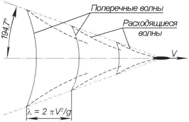
Over time, I came to the conclusion that an economical watercraft should be a displacement one, designed for a 5-7 hp motor. and a speed of 15-20 km/h, no more. From the point of view of the theory of a small vessel, this is a transitional regime, when hydrodynamic forces are not yet sufficient to achieve planing, but they are already sufficient for intense wave formation. Science states that in transient mode, wave drag makes up the bulk of the ship’s total resistance and recommends avoiding this mode. The picture of wave formation known from textbooks, the so-called Lord Kelvin wave system, is shown in the figure.
A ship moving at speed V creates two wave systems. Divergent, the envelope of which forms an angle of 19-20° with the ship’s trajectory (theoretically, exactly 19.47°). And transverse ones, the length of which can be calculated using the formula λ = 2πV2/g. The intensity of wave formation is determined by the relative speed of the vessel, called the Froude number F = V/√g 3 √D, where V [m/s] is the speed of the boat, D [t] is its displacement in tons, g = 9.81 m/s. The greatest wave formation is observed during the transitional mode of motion, when the Froude number is in the range from 1 to 3, which corresponds to speeds from 10 to 30 km/h for most small vessels. Thus, we will not be able to avoid movement in the transitional mode.
In shallow water, when the depth of the reservoir is comparable to the size of the vessel, the picture of wave formation is even more interesting. Divergent waves are almost not formed, but transverse waves increase so much that almost all the engine power is spent on their creation.
Are there ways to reduce wave formation? Yes, they exist, but for this, first of all, the ship’s hull must have a large elongation, as they say, “the length runs.” Shipbuilding practice has shown that the optimal elongation, that is, the ratio of the length of the hull to its width, should be in the range from 8 to 12. With greater elongation, the gain from reducing wave drag is largely “eaten up” by the increase in friction resistance. In addition, to reduce wave formation in transitional mode, the contours of the vessel must be quite smooth, and the stern must be streamlined so as not to “drag water.” And since in this mode the stern of the vessel falls directly into the trough of the transverse wave, it needs to be “lifted” by some means, for which you can use a sufficiently large aft section of the flat bottom, transom plates or a hydrofoil. You can also shift the centering forward.
For a multihull vessel, catamaran or trimaran, it is also necessary to take into account the superposition (interference) of waves created by its hulls. Shipbuilding practice has shown that there is no mutual influence of hulls harmful to resistance if the hulls are spaced so widely that diverging waves do not reach the adjacent hull. From the above diagram it follows that for this the distance between the housings must be greater than B = L*tg20° = 0.36L.
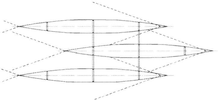
Is it possible to build a multihull so that the mutual influence of the hulls is not harmful, but beneficial, so that the waves they create do not amplify, but cancel each other out? In the case of a symmetrical catamaran, this is unrealistic, since the waves created by the hulls will always add up. But for a trimaran this is possible. Take a look at the wave pattern of a trimaran with three identical hulls, the middle of which is pushed forward relative to the other two. It can be seen that with the correct relative position of the bodies, the waves they create will cancel each other out.
This short and simple excursion into hydrodynamics will allow us to approach the construction of multihulls from a scientific point of view.
CATAMARAN ON FLOATS FROM “MEFODIUS”
The coronavirus epidemic and self-isolation at the dacha helped me move from dreams and theoretical reasoning to practical activity. Excess free time greatly promotes technical creativity…
There is a company called Methodius in the Moscow region, whose activities I have been watching with interest for a long time. There, using the rotational molding method, various boats and other watercraft are made from polyethylene, including floats of two sizes, the smaller of which was exactly suitable for my tasks.
One of the advantages of polyethylene boats is the ease of their repair. Polyethylene, as you know, glues very poorly, but it melts at a temperature of only 96 ° C. All damage can be easily repaired using a regular construction hair dryer, which I have tested in practice.
Possible moisture-resistant bridge decking materials
| Material | Density, g/cm 3 | Tensile strength, MPa | Dimensions of standard sheet, mm | Standard thickness, mm |
| Bakelized plywood FBS-1 | 1.2 | 78-117 | 2440 x 1220 (2500 x 1250) | 6-30 |
| Aviation plywood BP | 1.2 | — | 1550 x 1550 | 1-5 |
| Moisture-resistant birch plywood FSF | 0.7 | 61-96 | 2440 x 1220 (2500 x 1250), 1500×3000 (1525 x 3050) | 4—40 |
| Wood-laminated plastic chipboard-10 (delta wood) | 1.3 | 176-274 | 1520 x 1520 | 5-60 |
| Fiberglass STEF | 1.8 | 220 | 2000 x 1000 | 0.35-100 |
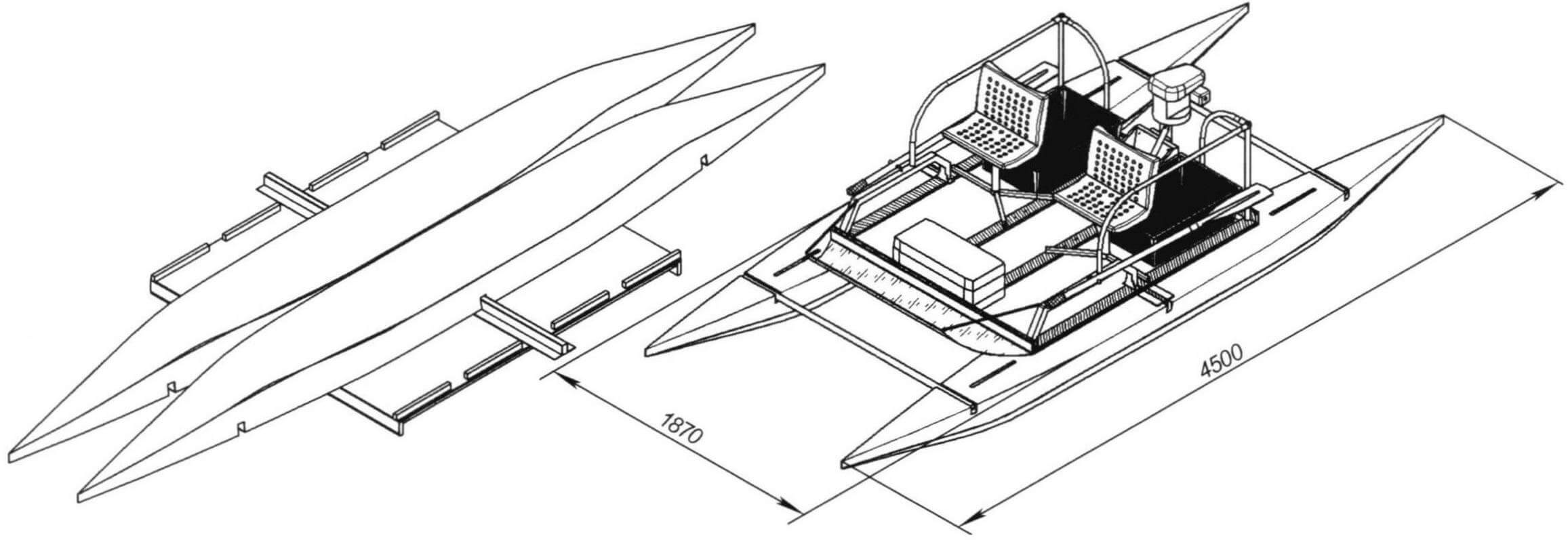
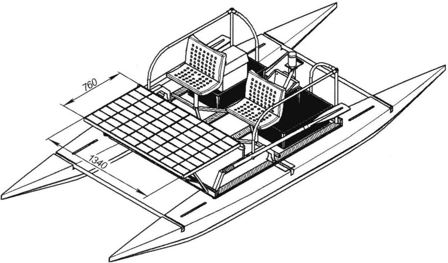
The length of the small polyethylene float from Methodius is 4500 mm, width – 400 mm, height -300 mm. The contours resemble the classic rounded shapes of a kayak, the bow and stern are symmetrical. There are longitudinal and transverse grooves for docking with the catamaran bridge. Float volume (total displacement) -0.28 m3, weight – only 18 kg. The load capacity of the float can be calculated as 0.5 * (280 kg – 18 kg) = 131 kg. Not much, but if you build a bridge correctly, remembering what we were taught at the Moscow Aviation Institute, you can get a good and very light two-seater motor catamaran.
First you need to decide on the sizes. The floats must be spaced as wide as possible: according to our formula, with L = 4500 mm, the distance between the bodies must be at least 1620 mm. However, there is another “introductory” one – the width of the top trunk of a UAZ car is 1500 mm. This means that the bridge will be exactly the same width, and the distance between the floats will have to be chosen the same way. The length of the cross beams can be slightly longer – up to 1800 mm across the overall width of the machine. The length of the bridge is determined from the experience of operating a planing catamaran: for a two-seater vessel, 1700 mm is quite enough.
To facilitate assembly and transportation, it is important that the weight of the assembled bridge does not exceed 25-30 kg. Its design for this should be the simplest: a transverse power beam that carries the entire load, and a light flooring. Bakelized plywood FBS-1 is best suited as a deck material. It is characterized by maximum water resistance, since during its production the veneer is impregnated with phenol-formaldehyde resin (bakelite varnish) before gluing. However, the dimensions of a standard FBS sheet are 2500 x 1250 mm, which does not make it possible to obtain a flooring from one sheet and will require reinforcement and weighting of the joint. For the same reason, and also because of the increased density compared to plywood, fiberglass sheets were rejected. There is another very interesting material on sale – wood-laminated plastic DSP-10 (not to be confused with particle board, which is correctly designated DSTP). This is nothing more than the famous delta wood, from which LaGG-3 fighters were built during the war. I was inclined to choose this particular material, but it turned out that in our “coronavirus” times we have to wait for more than one month for its delivery, which did not suit me at all. All that was left was the limited waterproof FSF plywood. It is also glued together with phenol-formaldehyde resins, but without preliminary impregnation, unfortunately. But it is produced in large sheets of 1500 x 3000 mm.
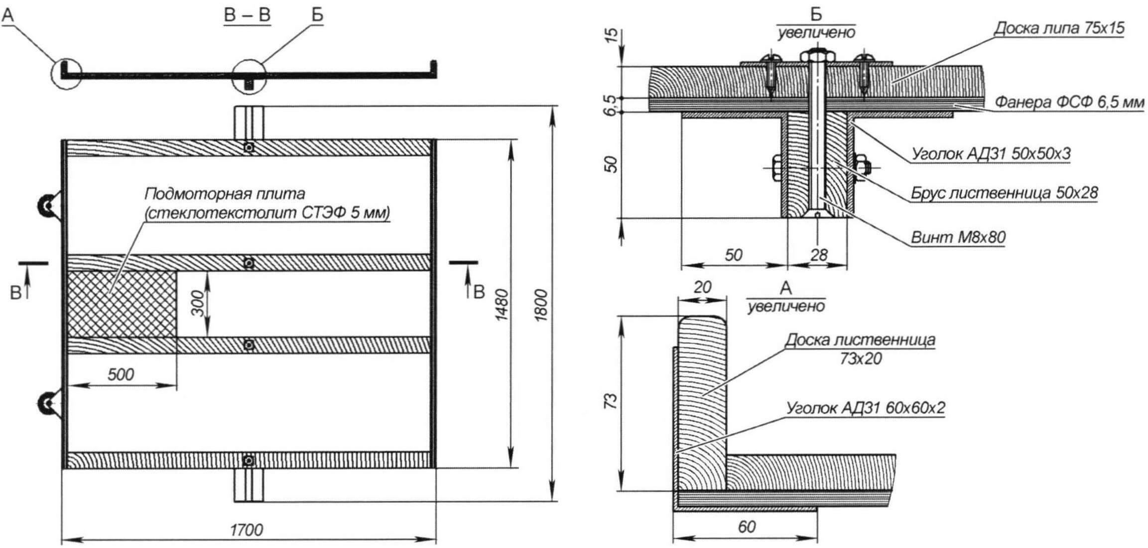
Amateur shipbuilders recommend using at least 5 mm for the thickness of plywood sheets, so that you can walk on it; I took it with a small margin – 6.5 mm. So, we decided on the material and dimensions of the bridge: FSF plywood, size 1700 x 1500 mm, thickness 6.5 mm.
The cross beam must bear the entire load, including the weight of two people. The best material for lightweight load-bearing structures has been and remains D16T duralumin. The aluminum-magnesium alloy AMg6 is slightly inferior to it in strength. But it welds well and is not subject to corrosion in sea water. While I was thinking about the choice, it turned out that these materials had also become difficult to obtain: regular domestic duralumin profiles can only be purchased to order, and you have to wait until the fall.
For the same reason, it turned out to be impossible to purchase a widely advertised new product – a fiberglass profile. During the “knockdown” period, all manufacturers “downsized” and offer only fiberglass reinforcement, that is, a simple round bar.
We could only rely on what was sold in construction stores near Moscow. But there was only an AD31 aluminum profile. This construction alloy of aluminum with magnesium and silicon is sold under the trade name “avial”, but has nothing to do with aviation. In terms of yield strength, it is more than four times “weaker” than duralumin. Its only advantage is high plasticity.
But in shops and markets, high-quality lumber was sold in abundance – from the strongest larch to the lightest linden. The high price for my small needs – just a few bars and planks – did not matter much.
Thus, limited by the realities of the “pandemic era,” I had to make a mixed structure using a durable larch block and auxiliary parts from “plasticine” aircraft. However, it is very similar that during the difficult years of the war, this is exactly how airplanes were built and nothing happened – they fought off the enemy!
Possible materials for load-bearing structures (standard profiles)
| Material | Density, g/cm 3 | Tensile strength, MPa | Yield strength, MPa |
| Duralumin D16T | 2.7 | 412 | 284 |
| Aluminum-magnesium alloy AMg6 | 2.64 | 314 | 157 |
| Avial AD31 | 2.67 | 127 | 69 |
| Fiberglass profile | 1.8 | 220 | — |
| Larch tree | 0.68 | 97 | — |
| Pine tree | 0.53 | 79 | — |
| Linden tree | 0.49 | 53 | — |
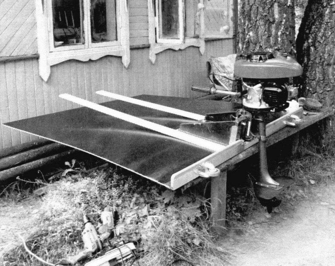
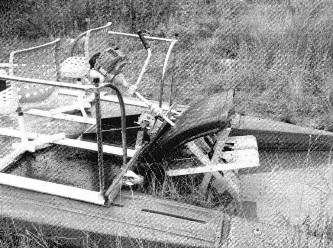
The bridge has a plywood deck, a transverse power beam of mixed construction 1800 mm long and two similar, but lightweight cross-beams: bow and stern. The stern takes the pushing forces and weight of the outboard motor, and the bow is designed to mount a wave breaker, solar panel, auxiliary bow motor bracket or removable canopy, as desired. The wave breaker is made of monolithic polycarbonate 2 mm thick. The flooring is reinforced with four longitudinal linden boards, and the installation site for the outboard motor is reinforced with a 5 mm thick fiberglass slab. Small wheels are installed on the rear traverse for transporting the bridge to the catamaran assembly site. The entire structure is assembled with screws and screws and glued with epoxy glue.
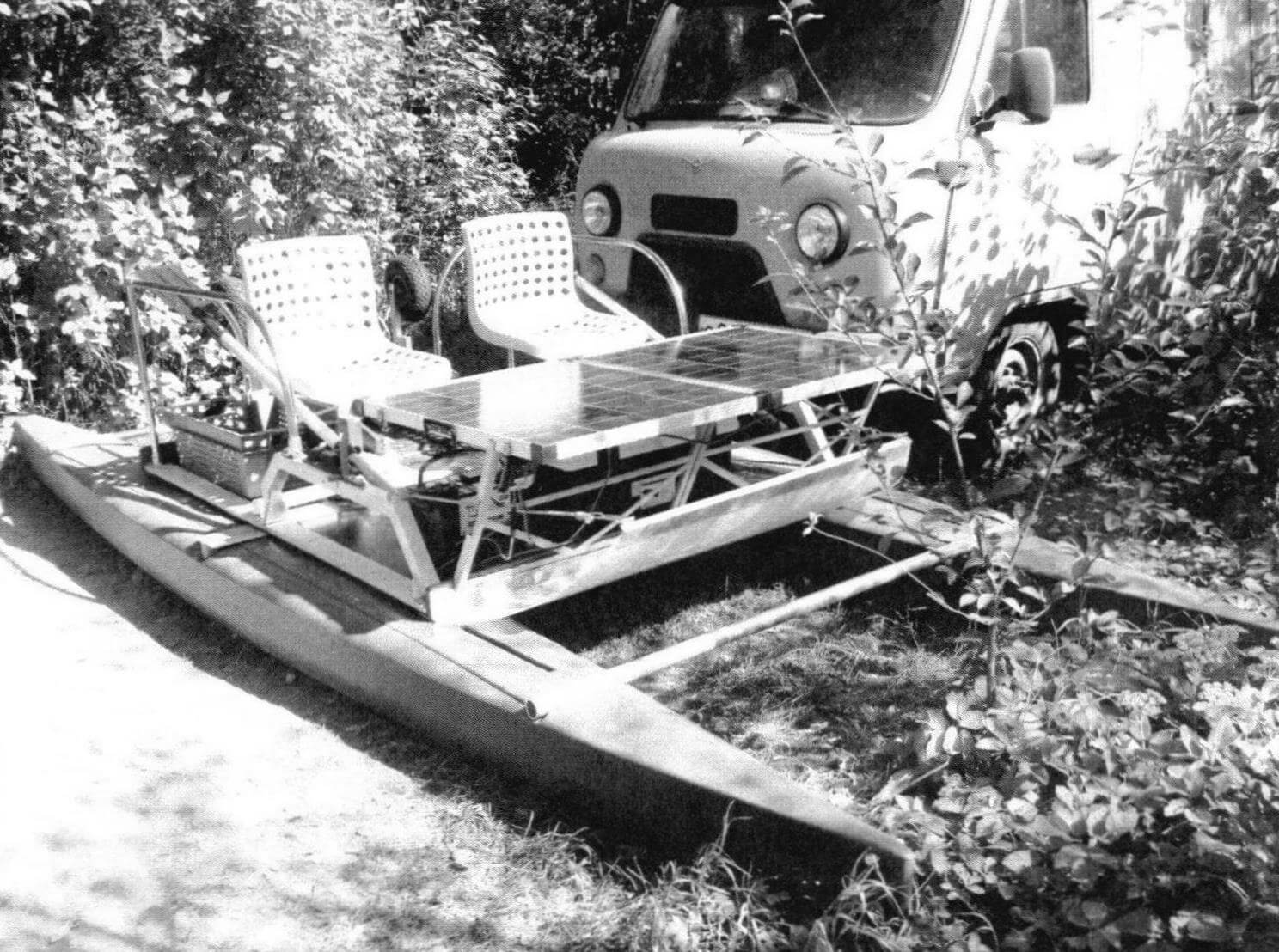
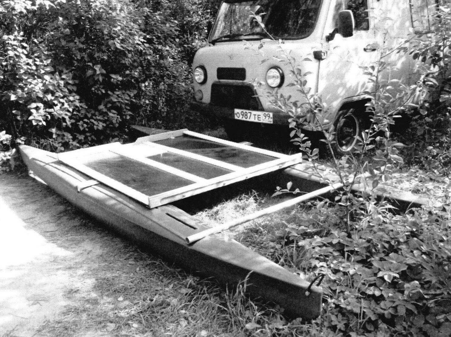
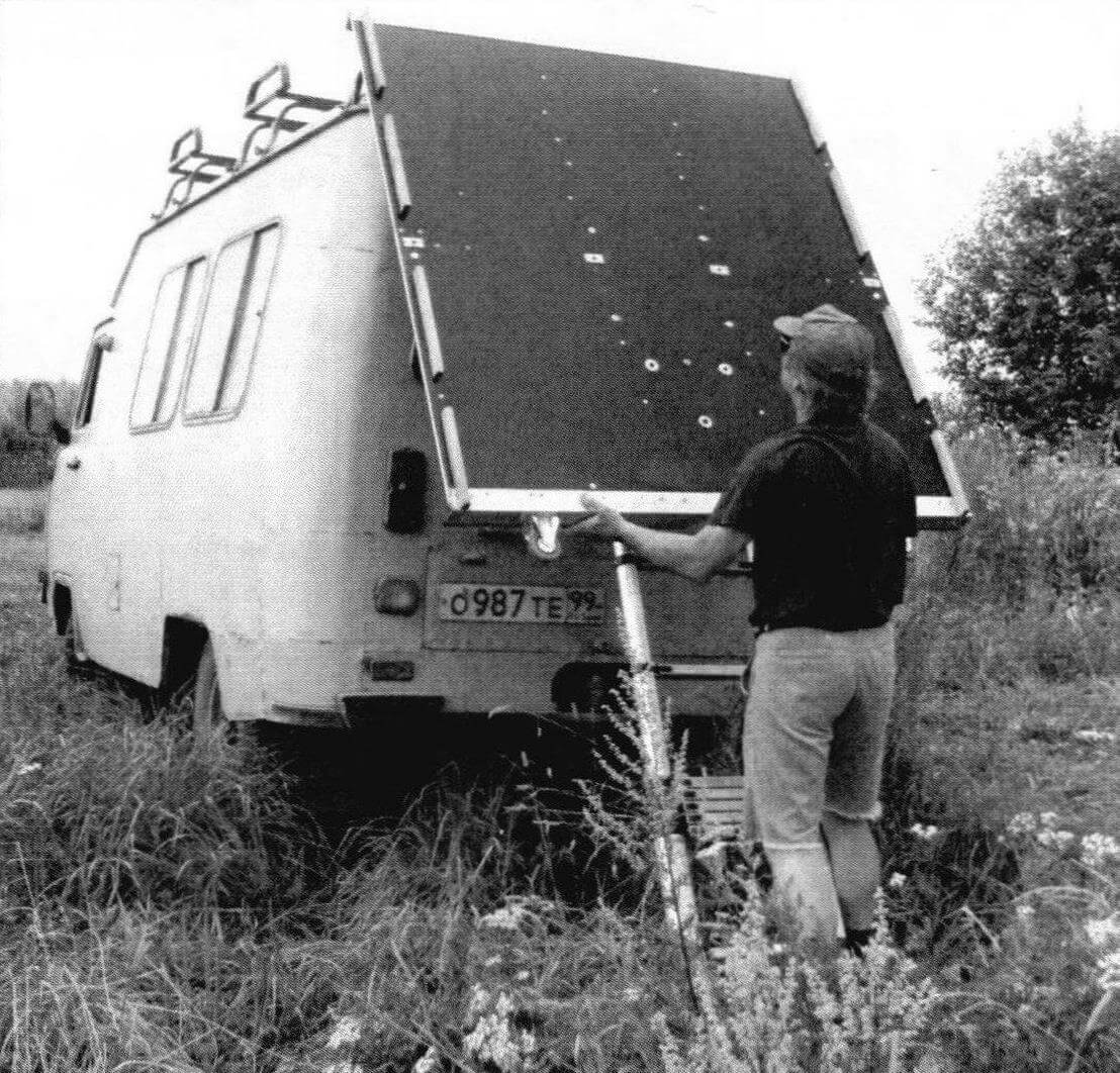
The mass of the assembled bridge was 29 kg. I thought it was too much for me and made the decking and cross beam detachable. Now the catamaran is loaded onto the trunk of the UAZ as follows: first, a deck with bow and stern crossbeams with a total weight of 23 kg is slid over, then a transverse power beam weighing 6 kg is attached to it, and then floats, each weighing 18 kg, are attached to it.
Swivel chairs, outboard motor bracket, railing, oars with brackets for them, luggage lockers are used from the previous design (see “M-K” No. 1-2020). The total weight of the assembled catamaran without outboard motor was about 95 kg.
SOLAR CATAMARAN
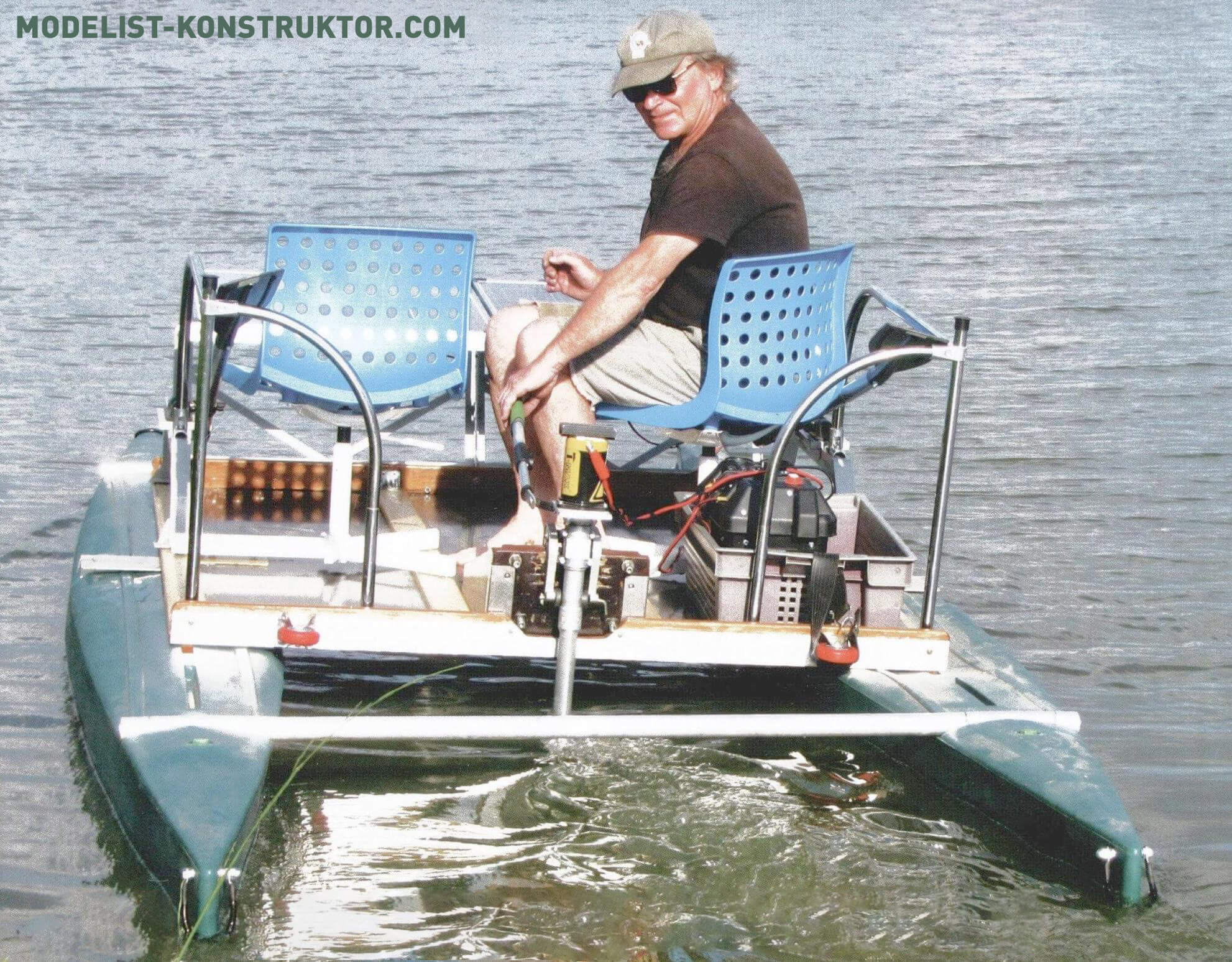
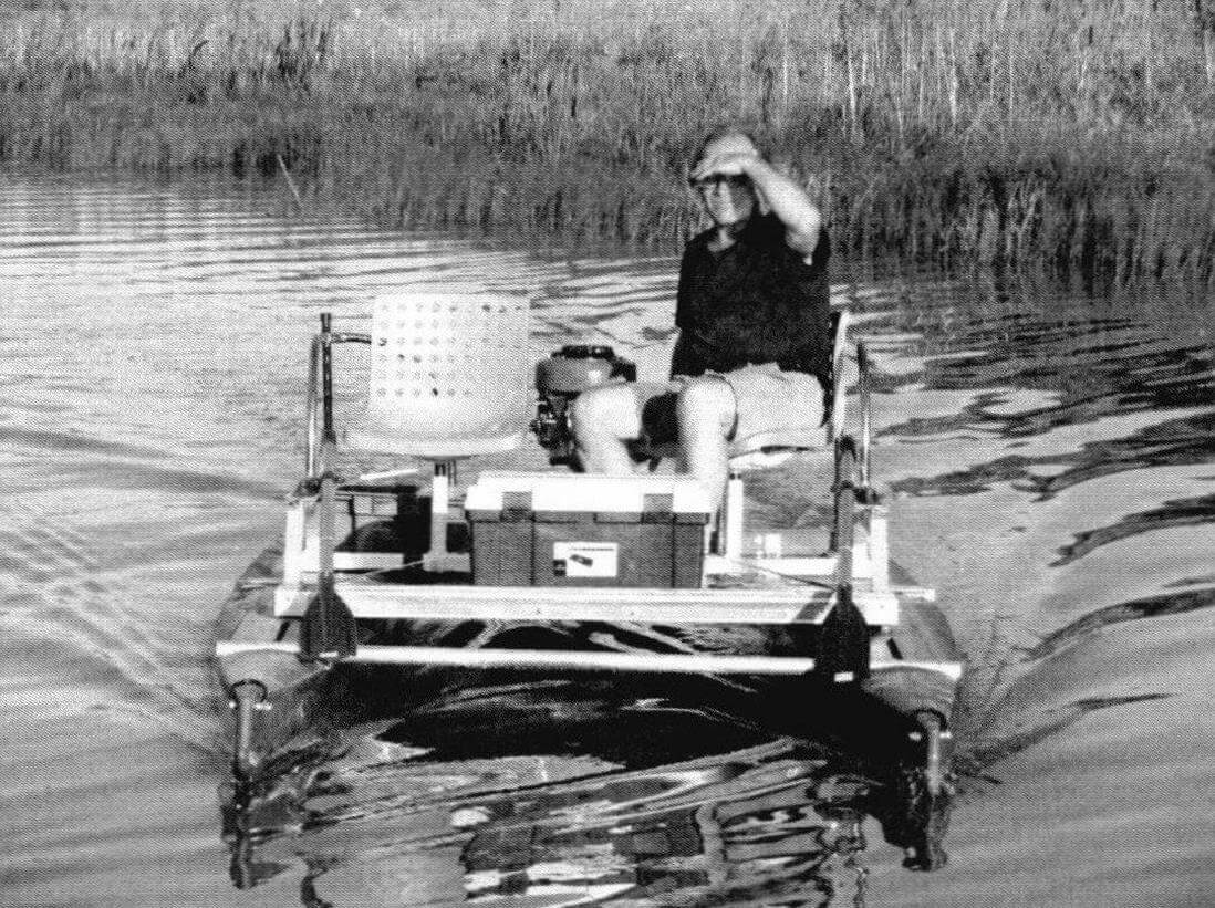
The photo of the assembled catamaran shows that a 150 W solar panel is installed in the bow of the bridge – this is a gift for my anniversary, as well as a continuation of experiments with electric propulsion, which began with the construction of a homemade boat electric motor and a 300 W power supply for it (see ” M-K” No. 6-2020).
The motor is a 12-volt DC motor from an electric winch mounted on the “leg” of a Soviet Salyut outboard motor. The current source is a power and control unit with a starter-traction marine lead-acid battery with a capacity of 85 A*h and a stepless PWM power consumption regulator. In my free time from “sea duty,” the battery is used on my expedition vehicle as one of two starters.
You can see that the maximum power of a solar battery under ideal lighting conditions is approximately half the maximum power of an electric motor. This was done deliberately: the excess power of the electric motor is needed as a reserve for difficult driving conditions, such as strong crosscurrents or strong winds. In this case, the power deficit is made up by a buffer battery, which can be recharged in the parking lot from the same solar panel or from a gas generator. It is interesting that the designers of environmentally friendly large ships with electric propulsion, which are now becoming fashionable, came to the same conclusion: the maximum power of the propulsion system should be approximately twice the total power of the solar panels.
The mass of the solar panel with a charging controller and fastening elements is 17 kg, the power supply and control unit with a buffer battery is 21 kg, the electric motor itself is about 6 kg, that is, in total, the same as a good boat motor with a power of about 30 hp. Is such weight justified by the ability to cut through expanses of water without gasoline? Let’s check this in practice!
SEA TESTS
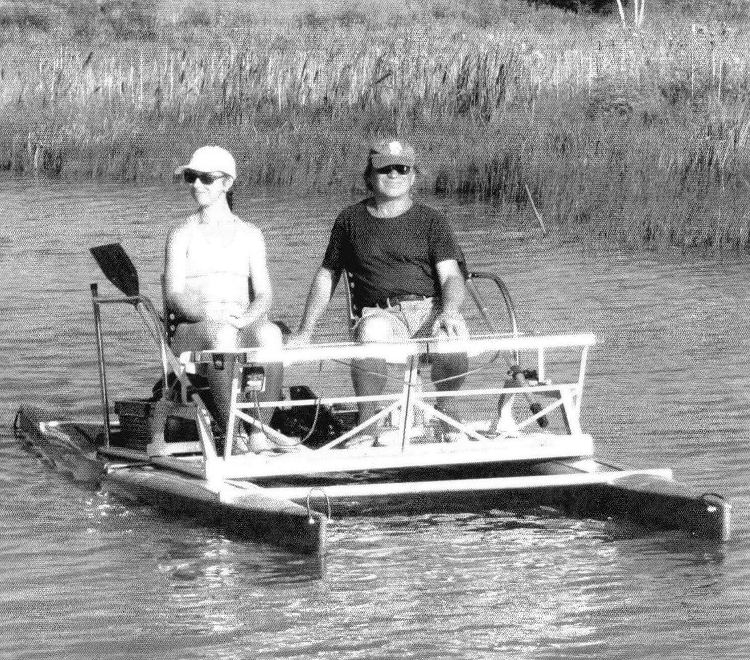
Unfortunately, the same restrictions that stimulated my creativity prevented me from conducting full-fledged tests on a long-distance hike. We had to use the body of water closest to the dacha as a testing ground. But, thanks to such a close location, over the summer I was able to try as many as two variants of multihulls with five different engines afloat and get the positive emotions from the joy of technical creativity necessary to improve immunity.
The first to water was a catamaran with a solar battery and a traction electric motor. The speed at a maximum power of 300 W was 6 km/h, with half a power of 150 watts – about 5 km/h. This is even a little more than the calculated one, which is explained, of course, with excellent hydrodynamics of floats. Testing for the swimming range was not carried out, since the length of the pond did not exceed 200 m.
When a rather strong oncoming wind blew, the catamaran with its great sailing was driven into coastal reeds. They managed to get out of them only at the full power of the electric motor, and once again I was convinced that 300 W is a minimally allowable power for confident swimming.
What are the general impressions of the tester and passengers? In the sense of pleasure from silent movement is great! But … no dynamics! At the same speed, the catamaran moves on the oars, and it is very easy on the go, and rowing equally convenient both forward and back: everything is symmetrical. For calm rivers and small forest lakes, this version of the power plant has the right to exist. In addition, we recall that in many interesting reservoirs, such as, for example, Senezhskoye and Pleshcheev of the lake, the use of PLM internal combustion is generally prohibited. You can raise a sail, of course, but for its use it is necessary to be a yachtsman, and this is a separate caste of lovers of rest on the water. I like the motors more.
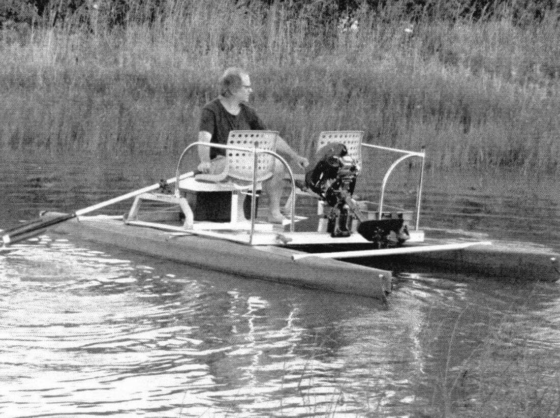
Having enjoyed plenty of silent and environmentally friendly pokatushki, I dismantled the solar power plant and put a homemade four -stroke engine with a capacity of 4 hp. And he was pleasantly surprised!
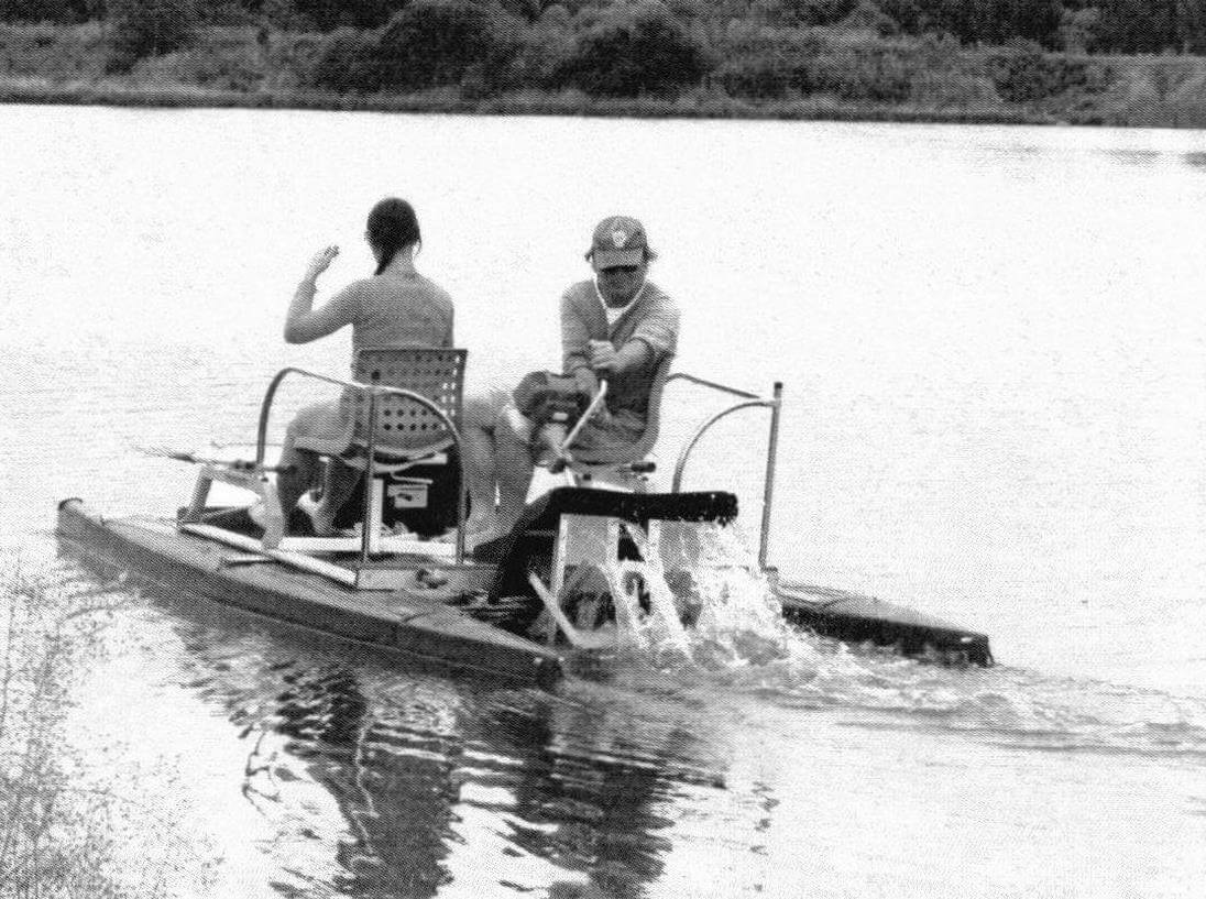
Without visible voltage, a very small motor dispelled the ship lightly up to 20 km/h, and with a full load of two people – up to 18 km/h. For comparison, the corresponding speeds on the launching catamaran and a small transubic boat were exceeded 12-15 km/h. Fuel consumption was a little more than 1 l/hour, which corresponds to a waybill of not more than 7 liters per 100 km. A great result is not only for the boat, but even for the car!
My favorite 1.5-horsepower motor with a wheelbuilder was tested (see M-K No. 12-2018). Its main advantage is the ability to move in the smallest and overgrown with aquatic vegetation places where it is difficult to even go on oars. True, the speed with such a power plant did not exceed the same 6 km/h. But even when the floats sat aground, the wheels, resting Plitsy on the ground, continued to push the catamaran forward.
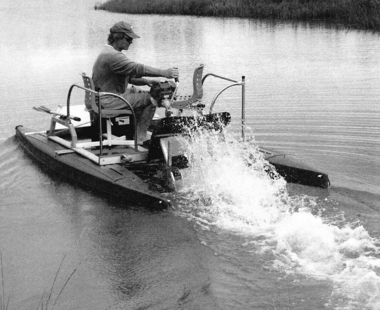
Do the new catamaran revealed shortcomings? Of course, how without them! Firstly, its maneuverability is noticeably worse than that of a single-body boat, which is understandable: the float is quite long, and the application point of the vinting force of the screw is not far from the middle of the vessel. A more significant drawback is limited seaworthiness (although this is impossible to check in the country pond). After all, a vertical clearance at full load is only about 100 mm, and even the wave of the chopper will probably not save from strong spraying. Although for calm reservoirs and even for large rivers this is a completely reliable and easy design that does not require registration and management documents under our laws.
Having received as a whole positive results, experiments with a catamaran at this stage ended, and I moved to the construction of a more complicated, but also more promising crafts – Trimaran. I’ll tell you about him in the next issue of the magazine.
Grigory Dyakonov
Recommend to read
 WITHOUT WASTING TIME
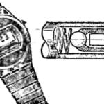
Men's watches and metal bracelets to them are often quite weighty. And spring-loaded axis connecting them, sometimes not withstand the load. But if you only break the pin, with the...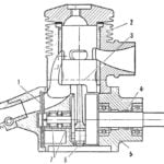 ENGINE — UNIVERSAL
To the editor of the magazine received a lot of letters in which modelers are asked to familiarize them with the device of the engine, designed by the Leningrad athlete E. Gusev. During...
