We live in a time when everything (well, almost everything) can be bought in a store – if only there was money. But, alas! There is always not enough money. In addition, not everyone is satisfied with the technical characteristics of commercial products. So you have to “turn on your head” and engage in amateur construction. In this article we will talk about building a buggy – a lightweight sports car intended for use by children or adults. I made my first such machines back in Soviet times according to the drawings of the Modelist-Constructor magazine. And then, over many years of working at the Avtoproject company, where many buggies for various purposes were manufactured, I accumulated quite a wealth of experience, which I want to share with the readers of the magazine.
In general, there is nothing complicated about the buggy. Most of the components for its construction can be purchased at auto stores. Or, if you have a workshop, make it yourself, which will significantly reduce the cost of the project. For example, for a children’s buggy, the most affordable materials and parts from motorcycles are used (silent blocks, steering knuckles, axle shafts, suspension elements), and to reduce labor intensity, the amount of turning work is kept to a minimum. However, as my long practice has shown, creating even a simple machine is impossible without drawings. Properly executed technical documentation at the design stage allows you to avoid errors (both directly constructive and financial) and will speed up the process.
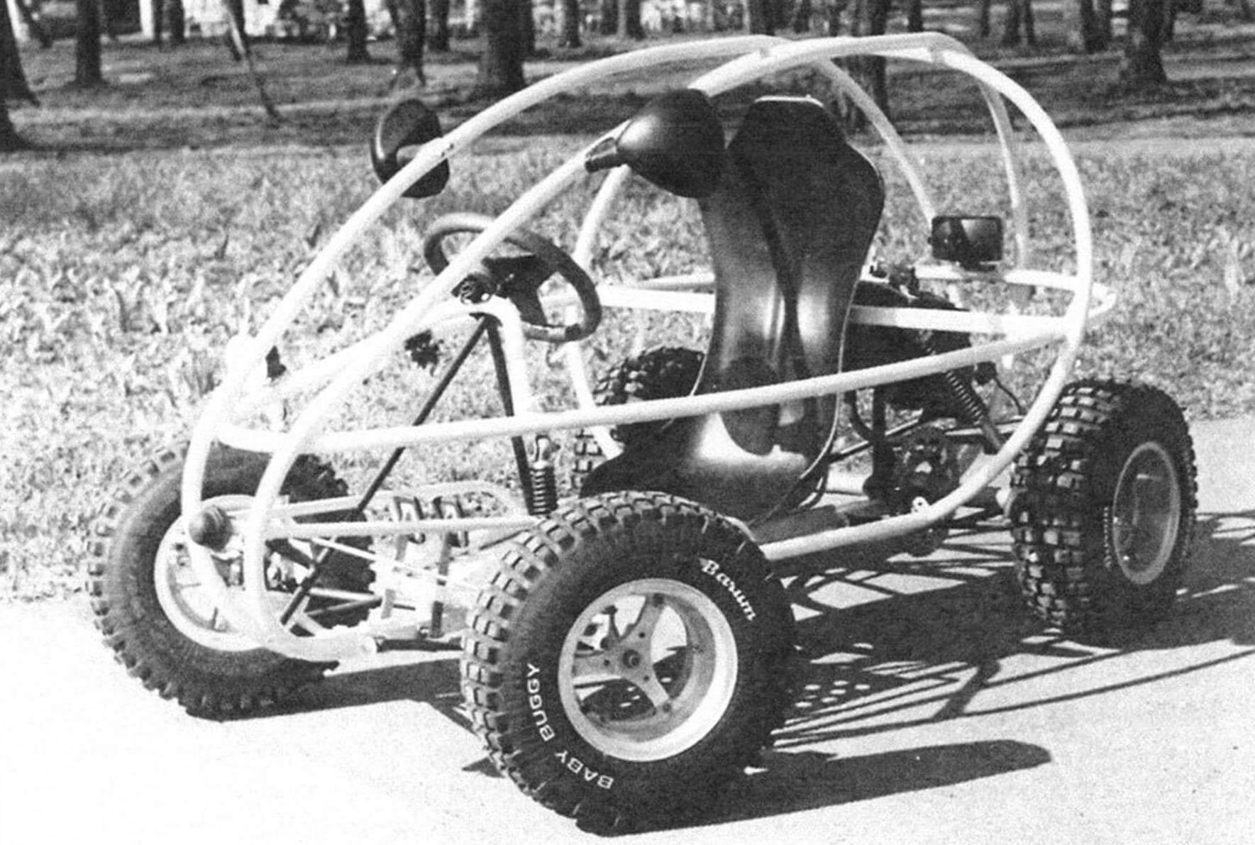
JUNIOR GROUP
Let’s start with buggies for teenagers. But before you get down to business, you need to decide for what purpose this car is intended: for the initial training of children in driving skills, for driving over rough terrain for tourism purposes, for rental business or sports? The answer to this question determines the safety margin of the design, the type/power of the power plant, as well as the maximum speed restrictions that must be ensured. It is also advisable to provide in advance the possibility of creating a multifunctional chassis with different options for the frame base and suspension design, with the ability to mount various bodies made of plywood, metal or plastic – this will be a foundation for the future, when a child who has already received some practice wants something new.
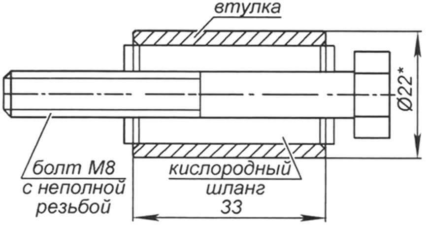
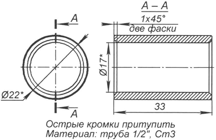
To make the base of the frame, a steel profile pipe with a cross section of 25×50 mm is suitable. If you have a pipe with a cross-section of 25×25 mm, it is possible to assemble from two pipes, welded “tack welded” along the length – the frame will be, although a little heavier, but more durable. Suspension arms can be made from scraps of water pipes: upper ones with a diameter of 17 mm, lower ones with a diameter of 22 mm. To ensure a smooth ride, the levers must be long enough; the optimal track width of a children’s buggy is 1250-1300 mm. The safety frame is made of pipes with a diameter of 25-34 mm. Silent blocks can be cut from an oxygen hose; to make them you will also need M8 bolts with partial threads.
The choice of tires and wheels should be approached quite responsibly, taking into account the intended operating mode: they directly affect safety. An affordable solution is wheels with a diameter of 400 to 480 mm and a width of about 100 mm. For a children’s car with electric drive and a maximum speed of up to 10-15 km/h, wheels from carts and garden wheelbarrows with the appropriate load capacity are a completely reasonable choice.
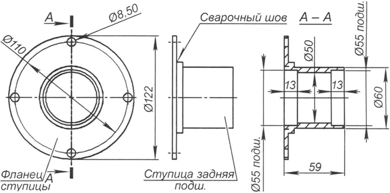
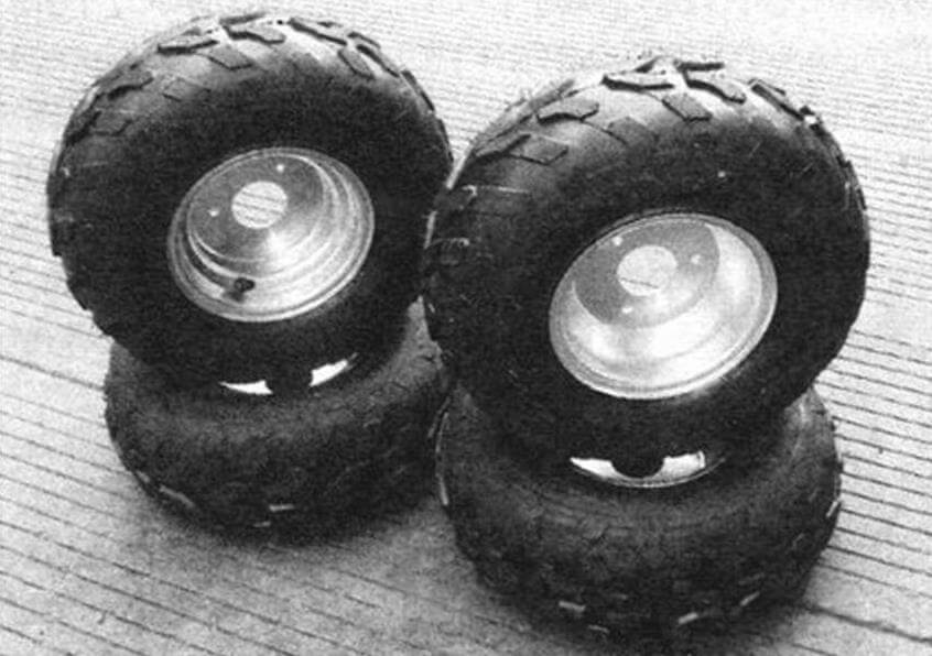
A more expensive, but more practical option for a buggy is to use a set of wheels from children’s ATVs measuring 7-8 inches. Serial rear hubs from the VAZ-2108, sold in any car store, are ideally suited for such discs, which will save on turning work. They are inexpensive, have a large margin of safety, and are suitable for both front and rear suspension. But they have a significant drawback – heavy weight. Therefore, if the task is to achieve high sports results at any cost, then the only way out is to manufacture custom-made parts in a modern turning workshop, with laser cutting and welding. The process is expensive, requires non-standard workpieces, and not every turner will undertake such work. But the result is worth the money and effort spent, since the weight of the unit can be significantly reduced.
If standard trolley wheels are used, then front hubs are not needed, since these wheels come complete with bearings (usually with an internal diameter of 20 mm). If the buggy is used with an electric motor, the same wheels can be installed on the rear axle, after first replacing the bearings with bushings.
Another possible solution is to use three-beam aluminum castings as discs, followed by machining on a lathe. They will fit both forward and backward. Their main advantage is trouble-free installation of brake discs and low weight.
A fiberglass seat for a buggy is preferable, since it is light in weight (no more than 2-2.2 kg) and can be easily transformed; I bought it and installed it in 10 minutes. A cheaper chair is made of plywood, covered with foam rubber and upholstered in any available fabric. It would be easy for someone with some metalworking skills to make a seat out of sheet metal, cut and bent similar to sports buckets. But in this case, the external covering of the chair with some kind of material is required.
One of the most important questions when building any car is what power unit to use? Recently, electric drives have been increasingly used for buggies. For a children’s car, an electric motor with a power of 0.5 to 1.0 kW is quite sufficient. The advantages are that they don’t need gasoline, they require almost no maintenance (dad won’t have to run around with a screwdriver), they don’t pollute the environment, and they operate silently. The disadvantages are the relatively high cost and short range, which requires infrastructure to charge the batteries.
As an alternative, a gasoline engine from a scooter with a displacement of up to 50 cc. see. Such units are usually supplied complete with a variator. The engine is started using an electric starter, which is convenient for children to use. But new components are also not cheap, especially since you will also have to purchase a fuel system, muffler, electrical wiring, and filters. However, there is a secondary market where it is not so difficult to find a used scooter as a donor. The standard braking system will also come in handy.
There are also gasoline engines – analogues of Honda with a volume of 160 to 200 cc. cm – they are now produced by many Chinese companies. But when using an engine of this type, additional components and assemblies will also be required. In particular, an automatic clutch and an intermediate sprocket shaft are required to provide the required gear ratio. Although there are options for a standard gearbox with an automatic clutch, which will allow you to do without an intermediate shaft. The main advantages of such engines are endurance and ease of operation. They are supplied complete and their price is lower than for scooter motors. But most of them are started by a cord, like a simple boat motor, and not by an electric starter.
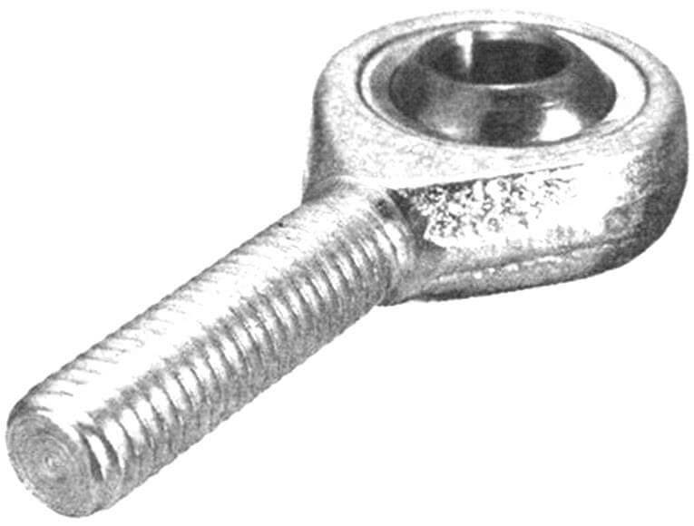
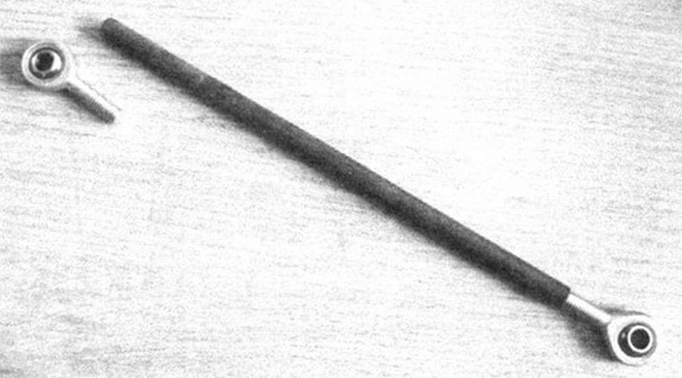
Let’s move on to the steering system. The simplest and most accessible thing is to take the lever control from a go-kart. Today, joint heads Sa10,12,14 are optimally suited for tie rod ends and ball joints. They are inexpensive and sold in many stores. If the buggy is operated at low speed, Sa8 tips are sufficient, for more intense loads – Sa10. They have proven themselves well in children’s autocross, where speeds over rough terrain reach 80 – 100 km/h. Sa12 is suitable for the upper ball joints, Sa12 or Sa14 for the lower ones. To eliminate the cost of turning, to make bushings for levers for balls and ends, it is enough to buy tall nuts (20-25 mm long). They are welded onto the levers under the hinge heads. For the steering rods themselves, the optimal choice is to select pipes and then cut the appropriate threads on them. Since the steering wheel is also an important element of safety and ergonomics, it is better to purchase it ready-made; the most practical diameter for a child is 280-300 mm.
Shock absorbers can be used from mopeds or motorcycles. But, I repeat once again, a lot depends on the operating mode of the machine.
FOR THOSE WHO ARE OLDER…
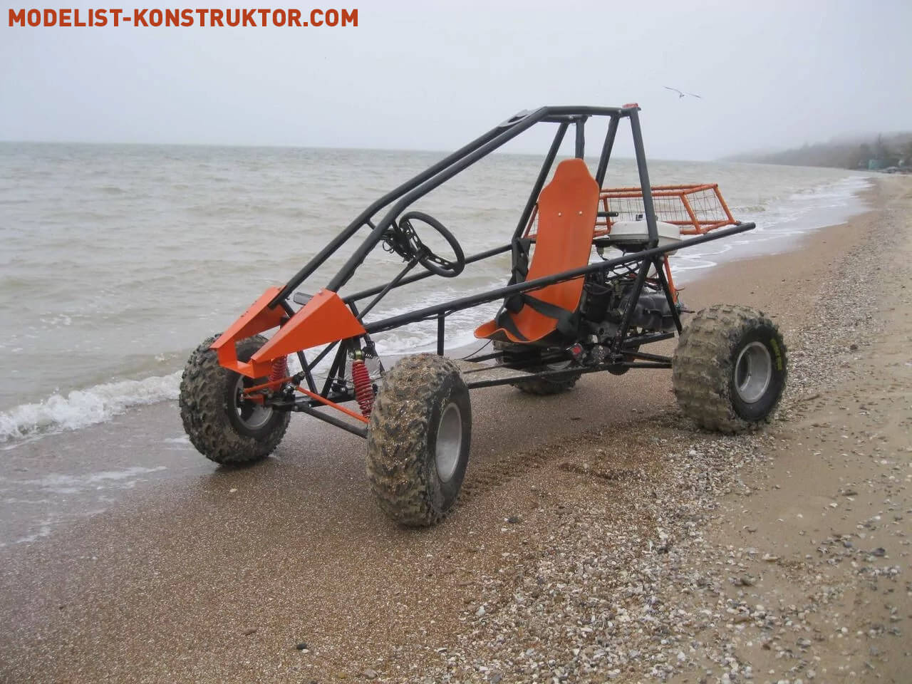
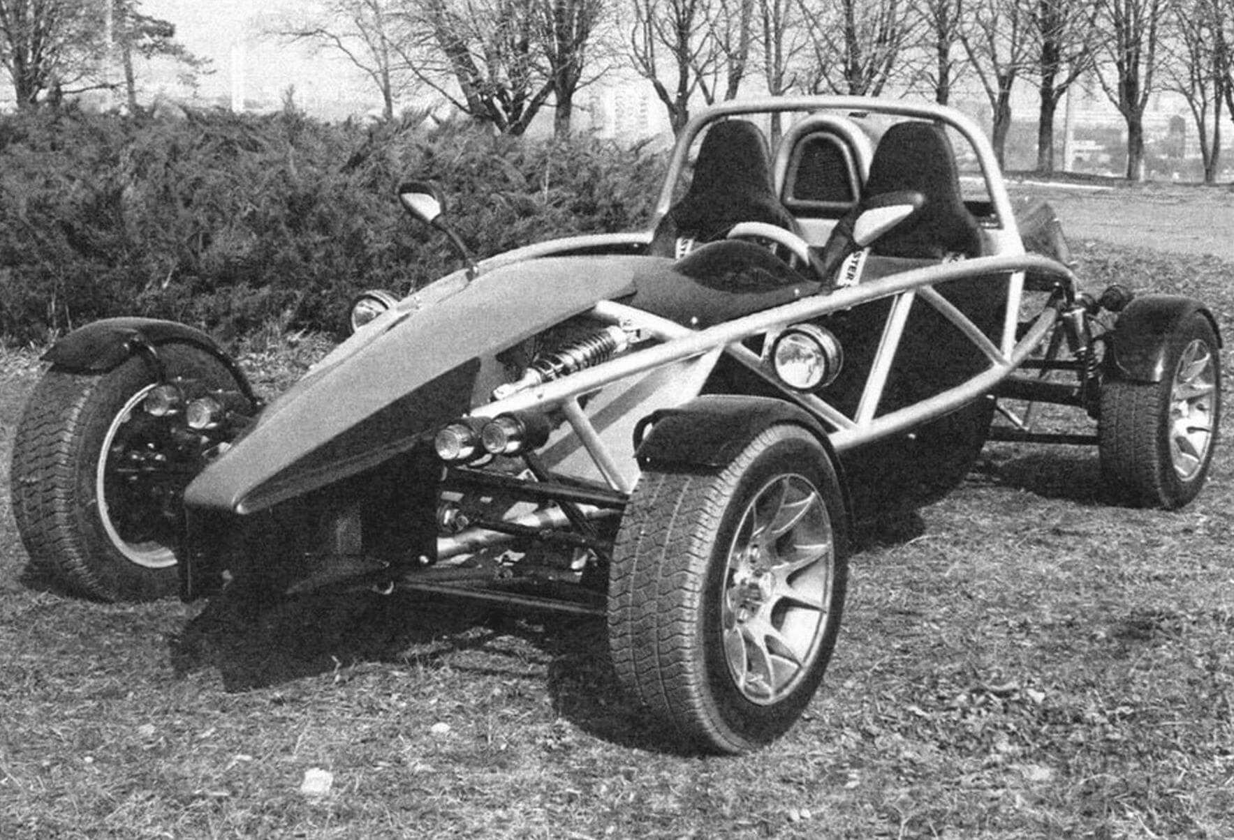
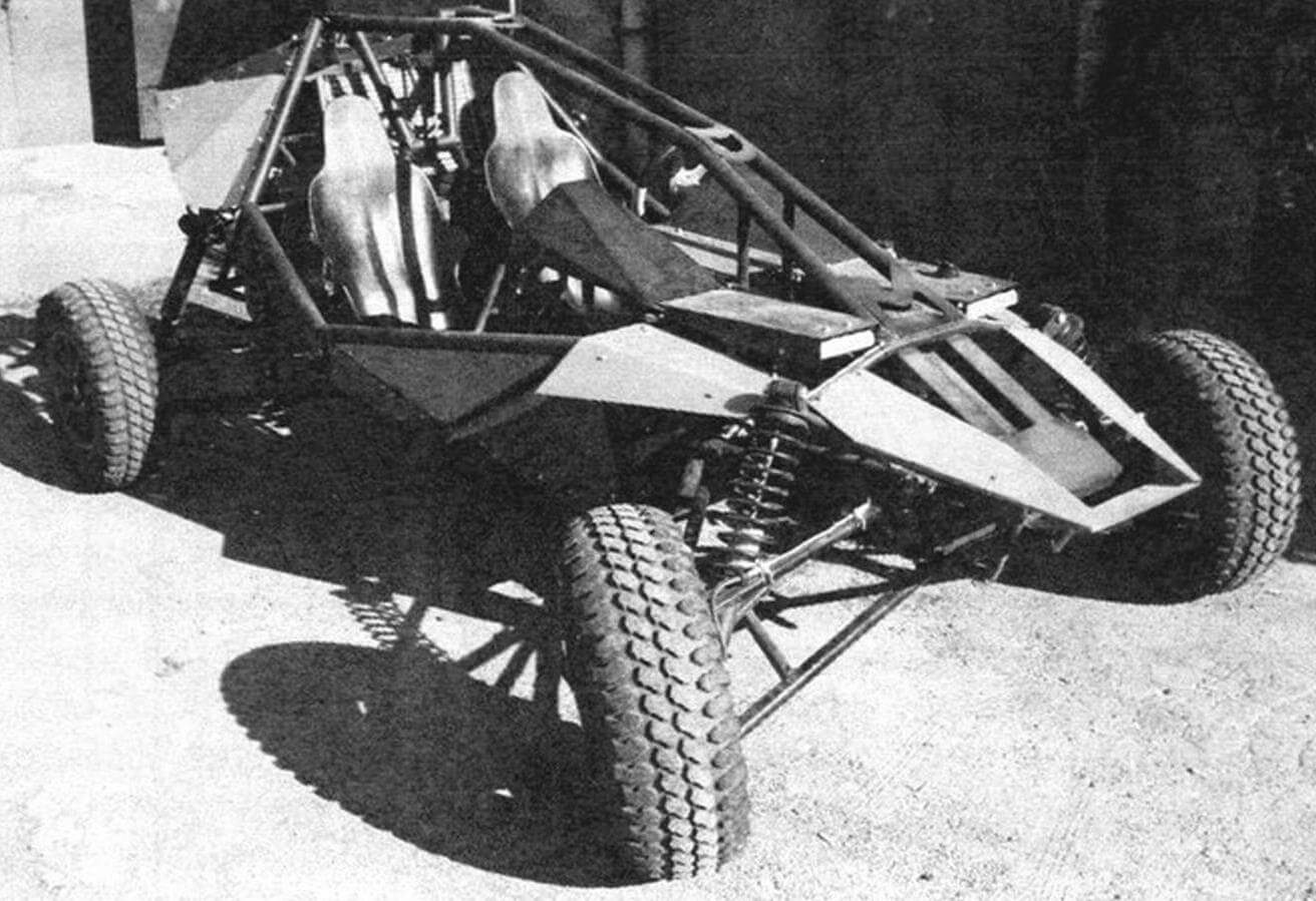
Using approximately the same scheme as a children’s buggy, you can build a completely decent device for an adult; you should only take into account the higher loads on the structure due to weight and speed. Since we are talking about a “buggy accessible to everyone,” we will consider the most budget option. That is, we use already existing inexpensive components, most of which for many car enthusiasts are probably gathering dust in the far corners of the garage, waiting for “better times.”
This project is a kind of “free program”, but in compliance with certain rules based on a clear algorithm, which I have repeatedly tested in practice. I think anyone can figure out the necessary and sufficient minimum of drawings – this does not require a diploma from a technical university. As for the rest, as they say, variations are possible. The only and main requirement for the master is that there should be no trousers with sleeves in his wardrobe.
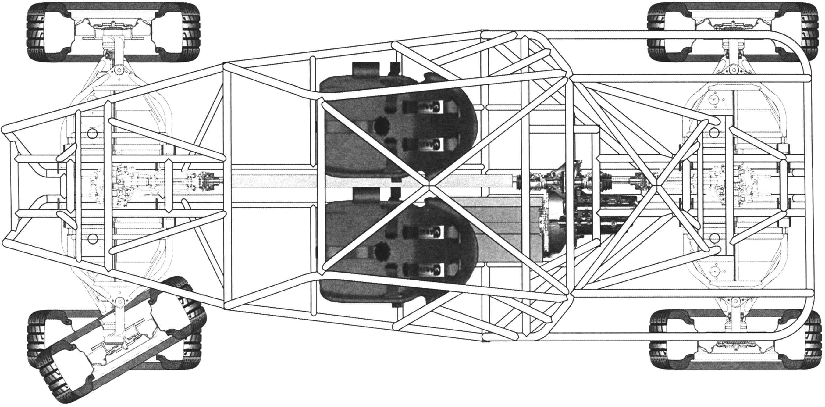
First, let’s sketch out a diagram with the preliminary geometric dimensions of the buggy. Optimal dimensions: width 1250-1300 mm, wheelbase 1350-1500 mm, length 1900-2100 mm. The exact values depend on the body. The estimated weight of such machines is from 80 to 120 kg (depending on the materials, components and parts used). The most suitable wheel size is diameter 400-500 mm, width 140-150 mm.
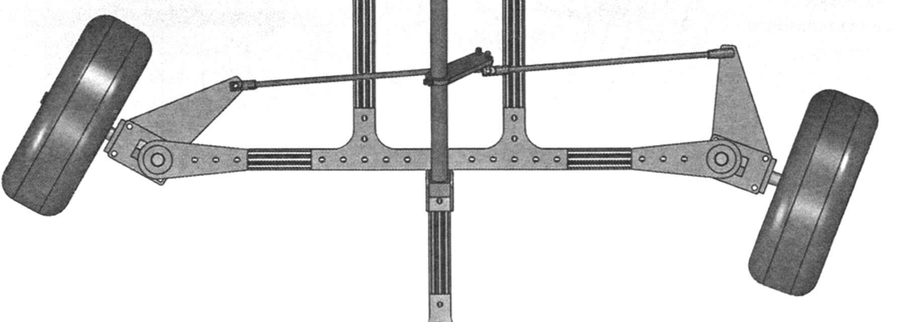
Next, you need to decide on the body frame and suspension components. We lay a “ridge” from a profile pipe along the longitudinal axis and first estimate the rolling axes of the lower arms based on the dimensions of the silent blocks and steering knuckles.
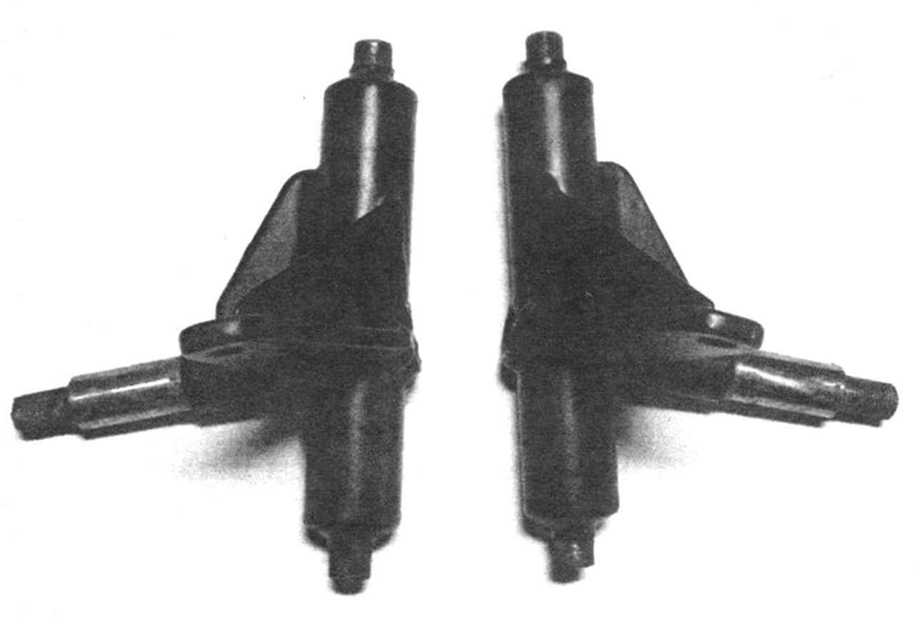
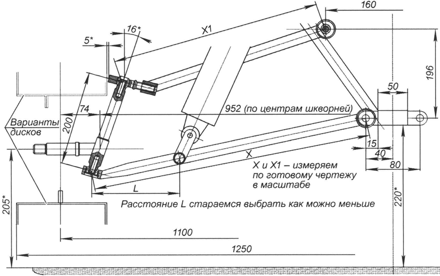
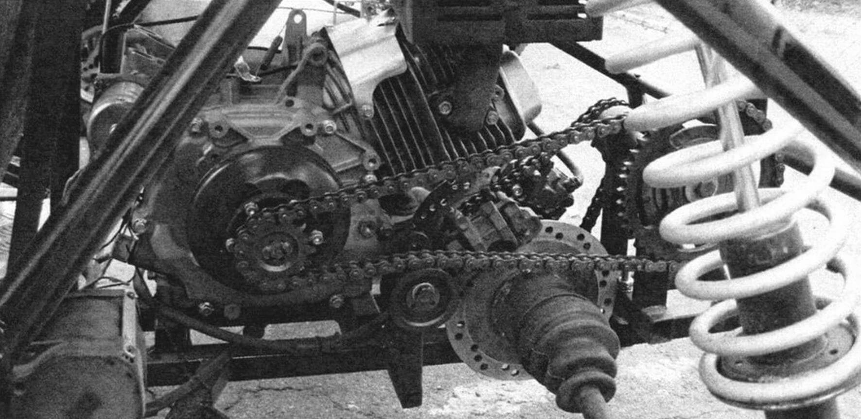
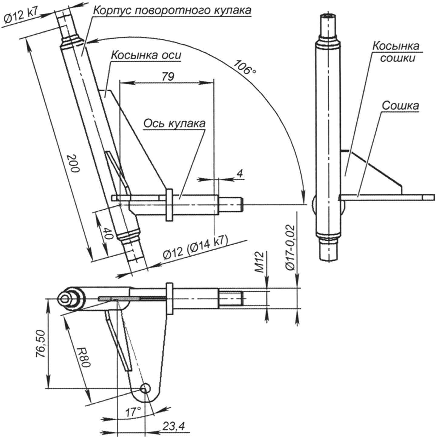
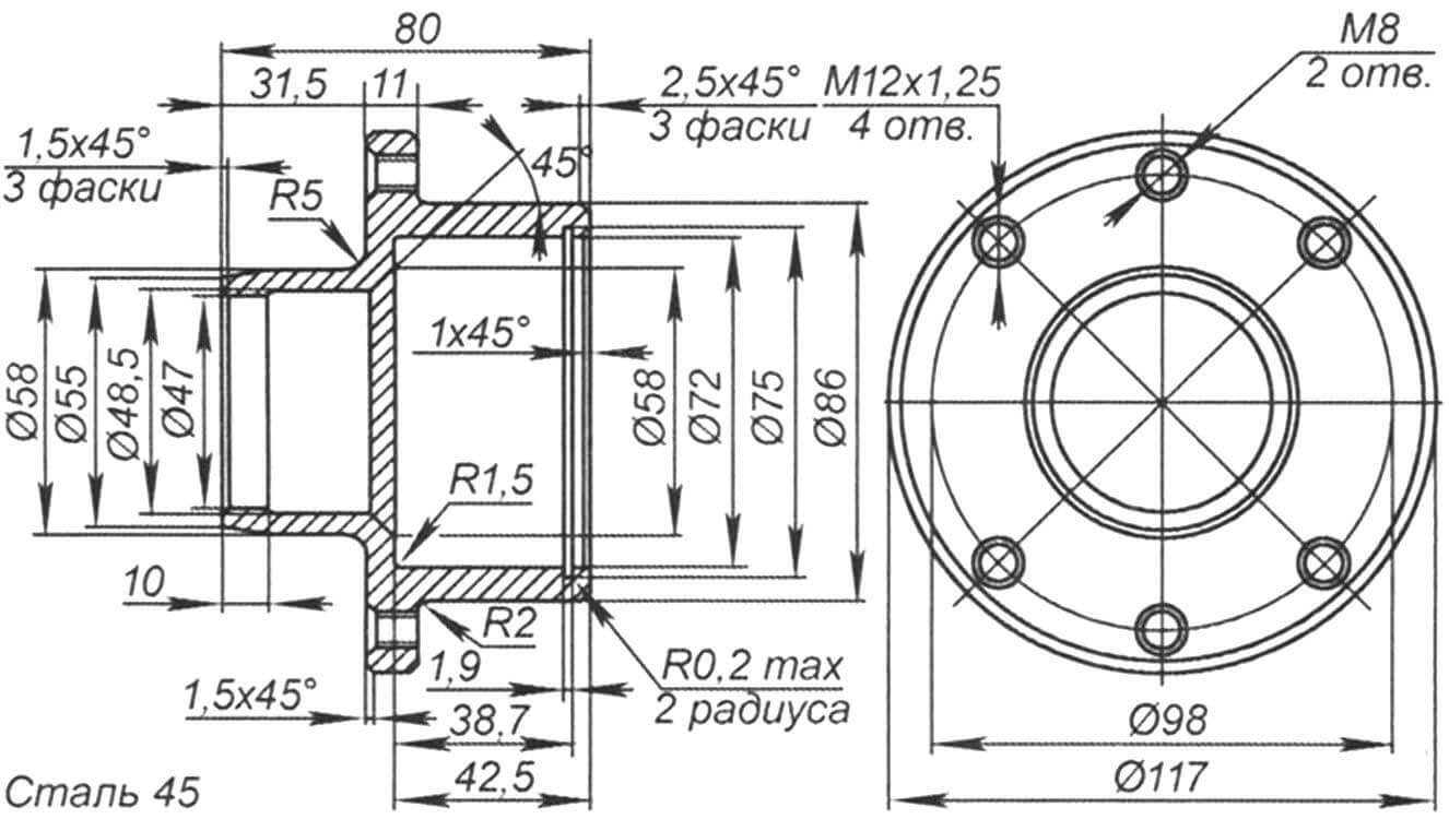
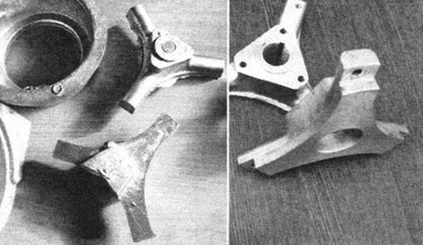
In our case, the steering knuckle consists of the following parts: a housing, which can be made from a piece of standard water pipe with a diameter of 21.5 mm, and two articulated heads Sa12 or Sa14 – their size depends on the weight of the structure, type of engine and design loads. For a light car or electric car, pipes with a diameter of 17 mm or 20 mm can be machined to the required size. You will also need to machine a solid axle with the same diameter. And make gussets for the bipod and axle, which can be cut from a strip of metal 2-3 mm thick. We cut out the bipod from sheet metal 5 mm thick or pipes with a diameter of 17 mm, welding a high M8-10 nut (corresponding to the selected ball head tip) onto one end. A possible option is shown in the drawing. The specified dimensions of the parts are taken from personal practice and tested on several dozen buggies.
As for the location of the bipod, the installation angles are also thought out and tested many times. I especially want to draw attention to the lines intersecting the axes of the fists. These are the lines on which the bipods of the steering knuckles are located, and the angle relative to the steering knuckle. Those who deviate from this scheme will not be shot, but will receive guaranteed discomfort in handling at speeds above 20 km/h.
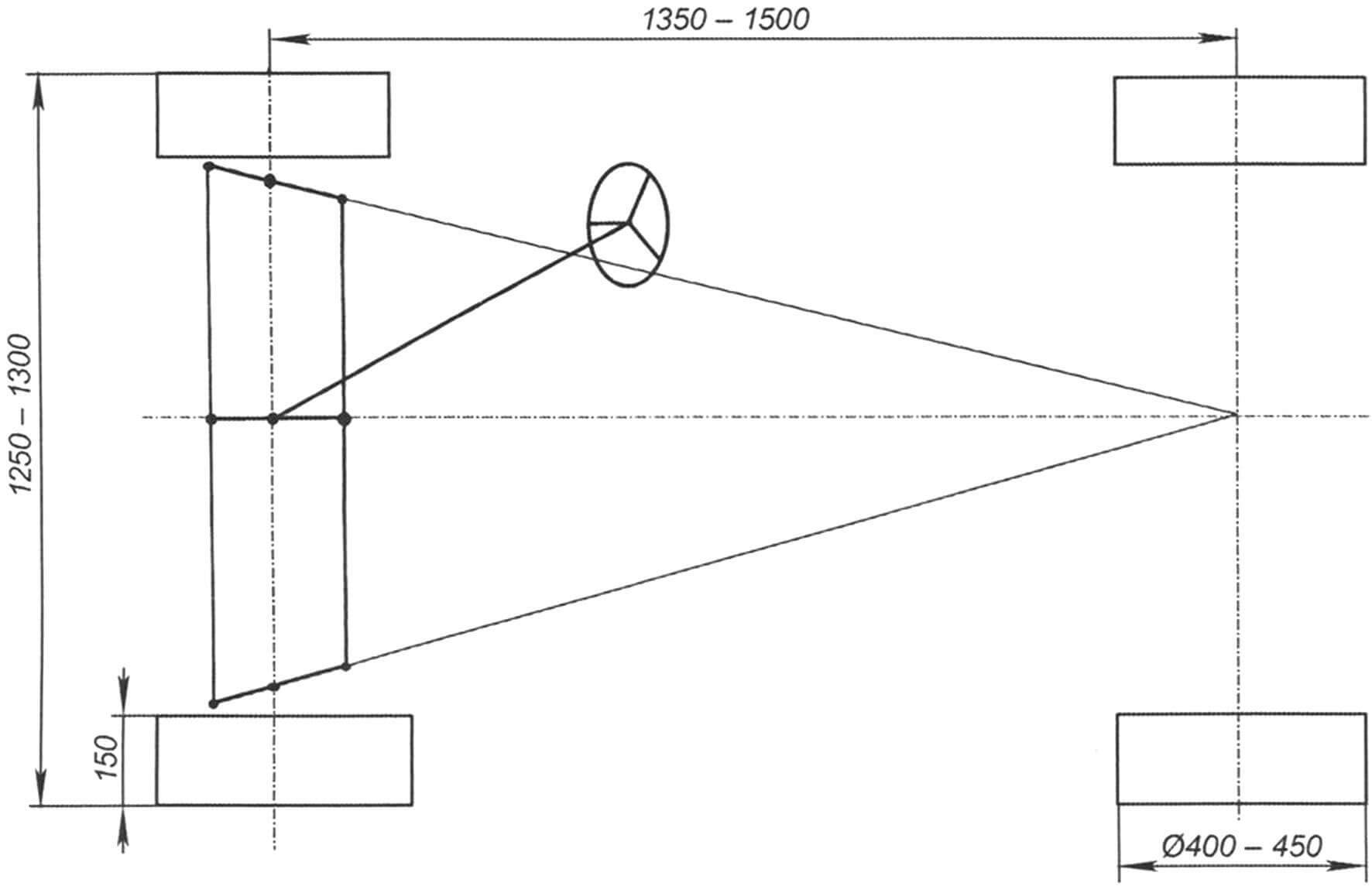
Steering rods can be located both in front of the front axle and at the rear – this is not a fundamental issue. For the handling of a vehicle of this size, their location does not matter much. Although there is a difference in the layout and overall overall dimensions of the machine. The front steering linkage improves ergonomics by increasing the distance from the pedals to the seats. And since with this arrangement the steering rods work in tension, they can be made from a pipe of a smaller diameter and the risk of bending them is minimized. However, the rear tie rods are better protected from impacts when hitting an obstacle, but at the same time they limit the space in the cabin. My choice is for the tie rods at the front. True, there is one important point here. Due to the tight layout, the bipod of the steering knuckles can enter the internal space of the wheel disk – this must be taken into account at the design stage. With rear tie rods, this problem does not exist. The ear for fastening the levers can be made from a strip of metal 3 mm thick and make a hole in it with a diameter of 8 mm for the bolt for fastening the silent blocks.
Vitaly ALEKHIN (Avtoproject company), Mariupol, Ukraine
Recommend to read
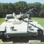 T92 LIGHT TANK
Received in 1966 the US Army light tank М551 Sheridan made a splash among specialists. The case of aluminum alloys, 152-mm gun — launcher ATGM "Shillelagh", the ability of the transport...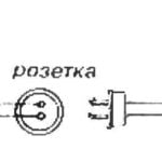 IF FORGOT ABOUT THE KETTLE
Insurance against burning out the heating element wikipesija the kettle samovar coffee pot or offer to make an extension cord with auxiliary power outlet and timer from the washing...
