 Letters a lot. One of them is to “brand” the forms of various enterprises and institutions, others on pieces of paper torn from a student notebook. But the questions are all about the same: the readers are interested in where, when and how you can get comprehensive information about gliders and hang gliding. We started in 1968 talking about a new kind of motorless flying has generated huge interest and gained the scope is truly inclusive. This, in our opinion, quite natural and not surprising: the level of technical training of young people is now high enough that even at home to build their own full-fledged glider. A shortage of necessary materials also does not stop enthusiasts of hang gliding. Difficulties in other: there is good, detailed and accurate drawings, which could produce details of the glider and the lack of experience and technological skills very often negates the attempt to make a dome (the sail). Reach extremes. In a letter to the seventh-grader Vladimir Nikitin of Sumy region photography barefoot boys. He flies with a small hill on a hang glider, made of spruce and covered with pieces of old red slogan.
Such correspondence a lot. They demonstrate the difficulties faced by enthusiasts of hang gliding on your way to your dream! But the glider is finally ready. Gleaming brand new parts, it stands on top of a hill, ready to fly and something like a huge bird.
And then start the main trouble! After all, there is still no official instructions or guidance on flight operations, safety regulations, etc., not to mention technique. Everyone is trying to fly on my own, at your own risk! And this is totally unacceptable.
Meanwhile, some social organization, first started in our country, the development of hang gliders, have already gained considerable experience, developed although still not all refined rules of organization and conduct of flights, laid the foundations of a technique for beginners. However, judging by the letters from readers, few people know how these organizations communicate and what help can count people who start everything from scratch. A curious detail: recently, our editors received a call from a public telephone enquiry service (the famous “09”) and asked ‘ clubs, hang gliders and other organizations, where young people involved in this sport.
Having carefully reviewed the letters received, we have compiled a list of questions that most interest our readers, and have prepared a compilation under the title — the glider without secrets.
Family of hang gliders Slavutich, established in Komsomolsk public design Bureau in Kiev enthusiasts hang glider appeared in the result of extensive research and complex flight tests conducted with the direct assistance of General designer Oleg Antonov. The participants of this work — the engineers of KB N. Kalashnikov, A. Peshkov, V. Moiseev and G. Makarov.
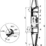
Fig. 1. The glider and its main components:
A — front node, B — the “top” of the mast In a side node, G is the Central node, D — tail node;
1 — pipe front flange, 2 — keel beam, 3 — mast, 4 — cross, 5 – a steering linkage, 6 safety washer, 7 — suspended system 8 — 11 — ropes.
Hang gliders of type “Slavutich” is intended for initial flight training for gliders, and the execution of training and record flights, participation in competitions.
The design of the devices all modifications consists of the following main elements (Fig. 1): frame, steering linkage, mast, rope stretch, dome and suspension systems. They allow you to use it in three ways: “Slavutich-1” are the most simple in management, it is recommended that for initial training of gliders; option 2 — transition, different from the first increased apex angle (80° to 84°). Modification of option 1 in option 2 is carried out by lengthening the transverse pipe 100 mm on each side (a connecting hole on the leading edge is transferred to the 120 mm back). It uses the same dome. Option 3 — sports, has an apex angle of 90°. In the modification of the framework revision is the same as for option 2, with a corresponding increase in the cross beam 210 mm and carrying a connecting hole on the front edge 280 mm back. The dome has increased in comparison with the other embodiments, the apex angle is 97°.
The theoretical scheme of the frame and plating, and the main geometric and performance data of options of hang gliding “, Savatic” shown in the figures.
DESIGN DESCRIPTION
Frame — the main hard part of the apparatus that defines its geometric characteristics. Main parts frame: two edges, keel beam, cross beam, bow knot, the Central, side and tail nodes. Edges, the keel and transverse tubular beam structures are the joints along the length in the adapter. In the center of the adapter coupling — connecting hole (Fig. 2). The pipe ends are plugged with wooden inserts by length equal to four pipe diameters, as shown in the figure. The ends of inserts are covered by epoxy resin. A connecting hole formed by inner diameter tubes inserted across the main pipe. When used as a material for these liners deletedrevision tube is not needed. Bow knot And connects the front edges and keel. Mount the nose of the node and pipe — 4 bolts M8. The distance between the axes of attachment of the front edges 150 mm. On the nasal node are set upper and lower fasteners of the front tether stretch marks.
Fig. 2. Design of parts and assemblies of the glider:
A diagram of the adjustment of the steering linkage along the length of the glider: 1 — suspension system of the pilot. 2 — adjusting strap, 3 — shields.
B — joining pipes using couplings: 1 — tubular rivet, 2 — connecting clutch, 3 — shields.
In the design of the connecting openings: 1 — connecting coupler, 2 — tube.
D — the scheme of location of connectors (when the length of the glider in folded condition about 2 m are used to label the connectors with a length of about 2.7 m connectors 1, 2 and 3 are not performed).
E — the Central node: 1 — mast. 2—keel beam, 3 — beam cross. 4 — washers. 5 — the center bolt, 6 — steering linkage.
And a side node: 1 — nut-lamb. 2 — pipe front flange, 3 — cross beam. 4 — wooden insert — bugey.
To — tail node: 1 — thunder (lanyard), 2 — wooden insert — bugey, 3 — lower rope stretching.
L — bow knot: 1 — upper cable stretch, 2 — wooden insert — bugey, 3 — lower rope stretching.
M — weight hull front, N — end Central node, the upper end of the Central node, N — washer P — plate cable bracket, mast mount plate cables, T — adjusting turnbuckle and method of sealing cable.
The Central node G is designed for connection poperechnoi and keel beams to each other, install the steering linkage and the mast. It consists of upper and lower U-shaped profiles, center bolt, insert the two tubular washers, spring washers and nuts. The lower the U-shaped profile is set to a steering linkage, this provides the possibility of its permutations along the keel at 35 mm from middle position. The upper U-shaped profile designed for installation of the mast.
The tail node D is designed to attach the rear cable stretch marks and consists of upper and lower fastening elements of stretching, mounting bolt, lock washer and wing nut.
Side node is designed for mounting cross Hoe and the front edge between them, and also for fastening terminal lugs cable side stretch marks.
A steering linkage is designed to control the glider, for mounting the suspension system and the lower cable stretch marks. It can be made in a collapsible or non-collapsible embodiments (Fig. 3).
The upper part of the trapezoid (Fig. 2) has bolted “step” for mounting the system. Each rung consists of M8 screws, lock washer and wing nut. Between the pipes trapeze installed the spacer tube (put on a bolt), providing a constant gap between them. Fixing the harness on one or another “step” enables you to change the alignment of the apparatus with pilot within 1 — 1,5%.
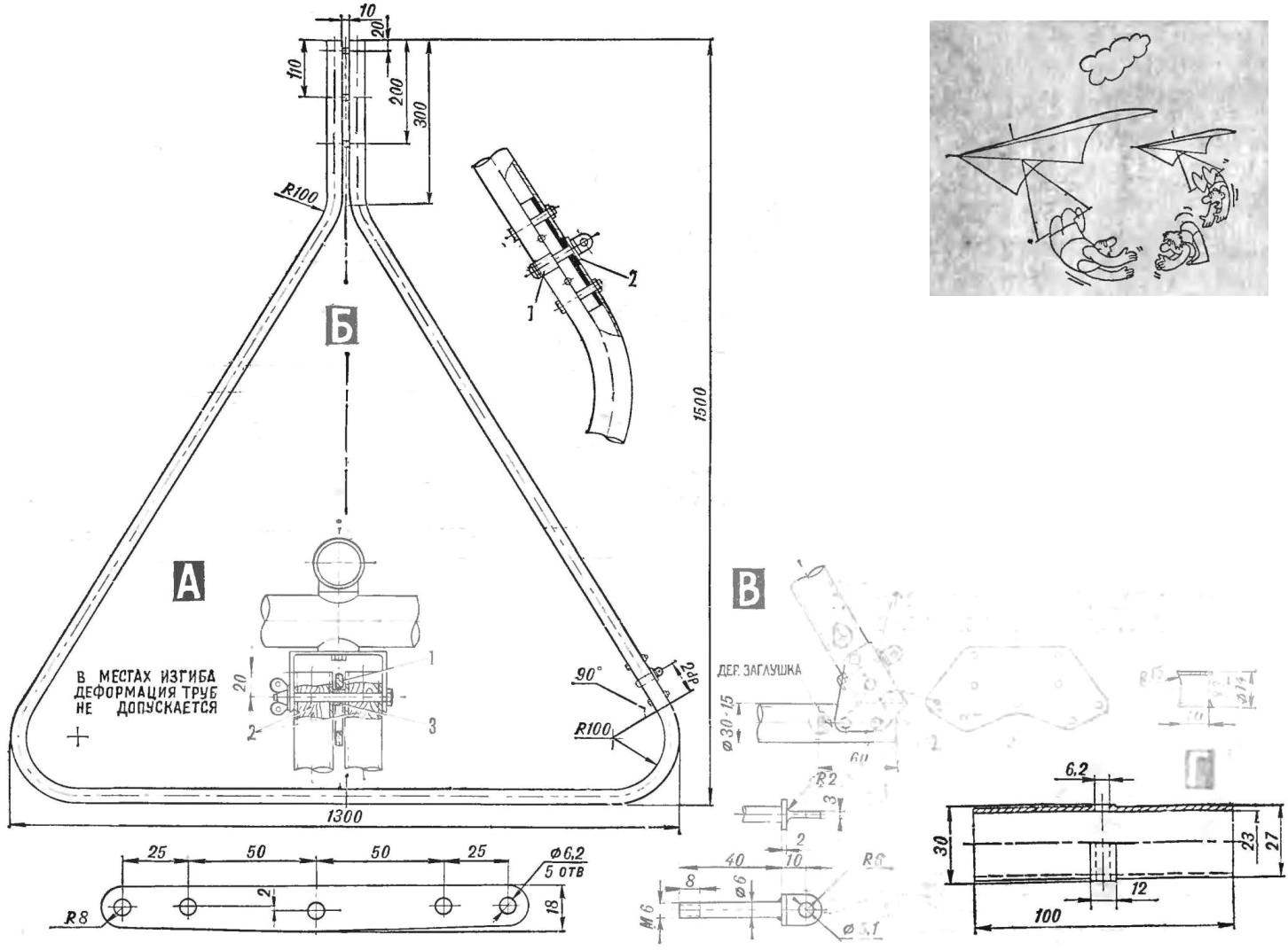
Fig. 3. Steering linkage:
And — fastening of a trapezoid to the frame: 1 — carabiner suspension pilot, 2 — wooden plug — bugey, 3 spacer (see also “In” on the right).
B — the steering trapezoid (top — connector design): 1 — adapter sleeve, 2 — Adjuster strap at the bottom – its in plan view.
In the version of the connector without the use of bent tubes: 1 — adjusting strap, 2 — overlay and its unfolding. Right spacer (om. also A” position 3). Bottom lug bolt.
G — adapter sleeve.
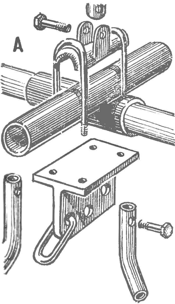
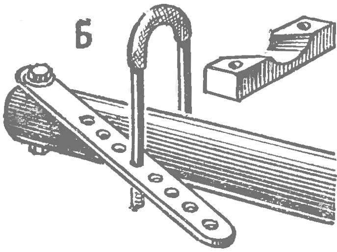
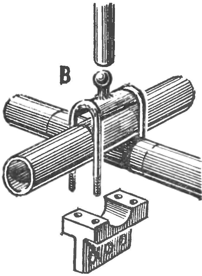
Fig. 4. Modification of knots used sections of gliders Tomsk, Leningrad and Rostov-on-don:
And Central node, B — side node — the node design is performed without drilling of the main pipes of the frame (development A. Antipova, Krasnoyarsk).
At the bottom of the lateral uprights of the trapezoid is set to the attachment of the lower cable extensions which consist of a lug M6 bolt, washers and self-locking nuts. In the place of installation of these nodes in the rack is inserted Couplings, such couplings of the main frame (Fig. 3G).
The mast is designed for mounting the upper cable stretch marks and consists of pipe and a cross-site cables. The knot of fastening of cables mounted on the mast by means of the insert and cotter pin (Fig. 2). Pipe masts attached to the upper U-shaped profile of the Central unit bolt M6.
Ropes provide the required rigidity of the frame and composed of upper and lower branches, which, in turn, are divided into front, side and rear. Front and rear lower ropes provide an opportunity to change the position of the steering linkage along the keel beam. This adjustment is provided by the tenders, adjusting P-obraznymi profiles on the nose and tail of the knots or adjusting straps on the side nodes of the trapezoid (Fig. 2). In the latter two cases, the thunder only serves to tension the front and rear cables. Tension adjustment of the lateral cables is also carried out using the turnbuckles.
(Should not continue)
A. DELIVER
Recommend to read
 A MODEL ROCKET CLASS S6A FROM KARELIA
Over the past 3 — 4 years in the lists of winners of major Russian competitions in sport flying are increasingly common names "rocket scientists" of the Republic of Karelia. So, on...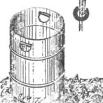 TWO-HANDED BARREL…
To lift and move manually to a large barrel and it is not easy and inconvenient: not to hold on. Meanwhile, equip it with a pair of convenient handles very easy. Do in the side wall at...
