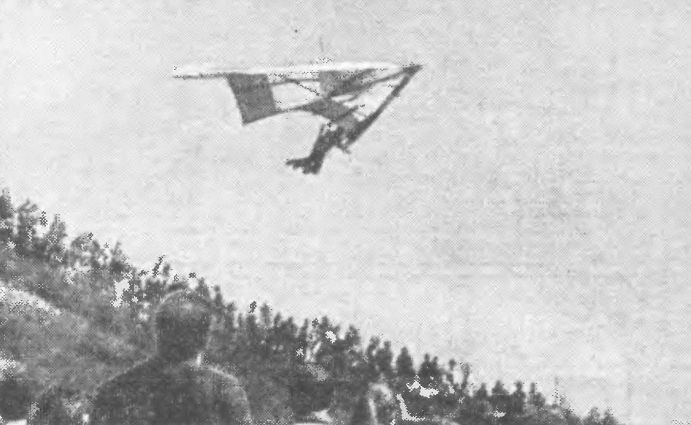
 “Fly higher, farther, faster!” This aircraft is the slogan became the motto of hang gliders. In our picture the glider master of sports M. B. Gokhberg. The front part of the dome is raised above the spar and forms a profile line, which significantly improves the aerodynamic efficiency of the machine. This glider Hochberg flew competition gliders Moscow area and became the absolute champion of the sum of three exercises.
In the previous issue we spoke in detail about the design of modern hang-gliders and gave first recommendations for the characterization and the production of the main elements of the “floating triangle”. The theme of this publication — recommendations for construction.
As already mentioned, to materials intended for the construction of the glider, very high requirements. The use of unacceptable substitutes. In the first place as a frame. For its production need seamless (seamless) pipe D16T such dimensions: the outer diameter of 40-45 mm, wall thickness 1 mm, length of 5.44 m (3 pieces if pipe full); Ø 36 — 45 mm, wall thickness 1.5 mm (or 32-38 mm, wall thickness 2 mm) length 4300 mm (cross). Pipe trapeze and masts — D1, Д16М; Ø 28-32 mm, wall thickness 1.5—2 mm. Bow knot — sheet steel 30KHGSA brand with a thickness of 1,5—2 mm. Profile the Central node of the steel with a wall thickness of not less than 2.5 mm. the attachment points of the cables 30KHGSA with a thickness of 2.0 mm connectors are machined from D16T. Pipe the washers and the liners — D16T, AK6, magnesium alloys.
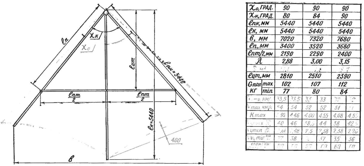
Fig. 1. The theoretical scheme of the glider-type “Slavutych” (legend, see table).
The main parameters of the three variants of hang glider “Slavutich” (see constructive scheme in figure 1) and the interdependence of them with flight characteristics (the latter calculated for a gross weight G floor. = 95 kg).
VP — vertical position of the pilot; GP — the horizontal position.
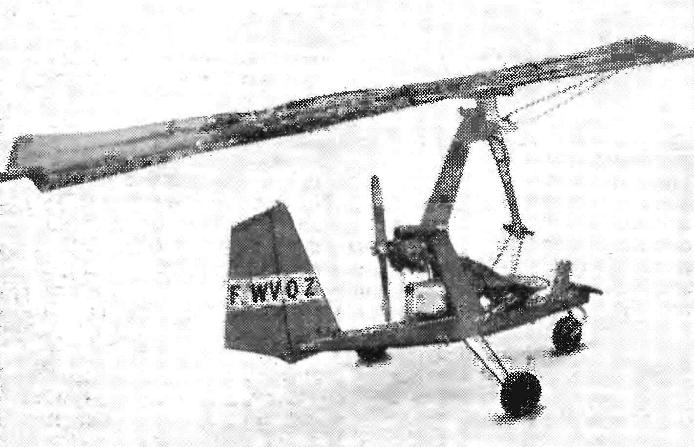
This single glider with a motor was demonstrated at the air show in Le Bourget (France). The fuselage resembles microalloy I. Banseka, but instead of the rotor (rotor) mounted on the triangular soft wing, which is a conventional hang glider with an area of about 30 m2. Control of the wing is a lever with two arms, one of which is connected by flexible cable to the throttle valve of the carburetor, the pedals control both rudder and front wheel chassis, which is very convenient for taxiing. Engine two-cylinder, opposed, with a pusher propeller with 30 HP Draw attention to the extremely rational form of the fuselage and pylon, as well as reactive, tuned exhaust pipes of the engine. Supply of fuel to the 40 min flight is under the engine in a transparent plastic canister.
The dome material: Dacron, calendered polyester, nylon, Bologna. Webbing suspension system: nylon ribbon, linen breeching width of 50-70 mm with a tensile resistance of the order of 500 kg.
Coating of metal parts of suspension systems (locks, buckles): of aluminum — anodized, steel — cadmium plating or passivation.
Ropes: rope brand KSAN; bottom — Ø 2,2—2,5 mm, the upper —1,8—2 mm.
The strength of pipe joints and connectors is carried out by the internal dimensions of the connecting tubes (see drawings). To exclude abrupt changes in stiffness in a couple of “pipe — coupling” the ends of the coupling are made cross-cuts on a length of 30-40 mm, the cut groove should have a width of 1-1,5 mm and end is drilled in the wall of the coupling hole Ø 3— 4 mm. Mount the coupling with pipes from one side blind rivets Ø 3 mm and epoxy glue, the other on a sliding fit. Pipe bending pipe bending using the trapeze fixture. Pre-annealing is conducted at 280-300°. The internal cavity of the pipe stuffed with finely sifted dry sand and the ends are closed tight wooden plugs.
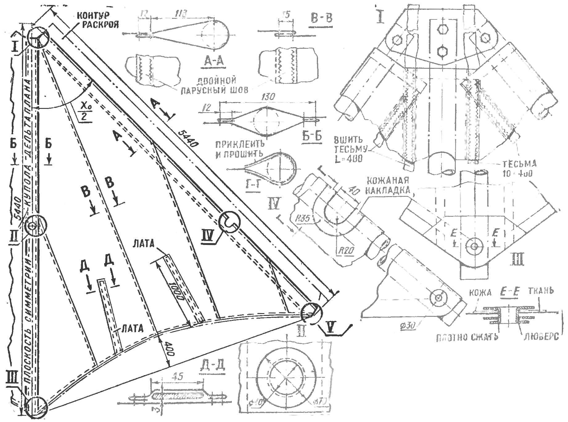
Cutting of the dome depends on the type of fabric. Seams must be positioned so that they do not create additional folds in the dome. The most economical location of the seams parallel to the keel beam. So should stitch fabric, having approximately equal compliance stretchable in all directions. The location of the seams parallel to the rear edge increases the strength of the dome, but it is difficult to avoid the formation of surface undulations along its chord. For most tissues, as shown, the best location of the seams is at an angle to the keel beam is equal to the inner corner of the dome (in the background).
Fig. 2. The design of the sails (dome), the technology performance of joints, sealing holes and corners, mount the dome to the frame; a dome in the plan (the diagram shows an advantageous arrangement of panels with a width of not more than 900 mm).
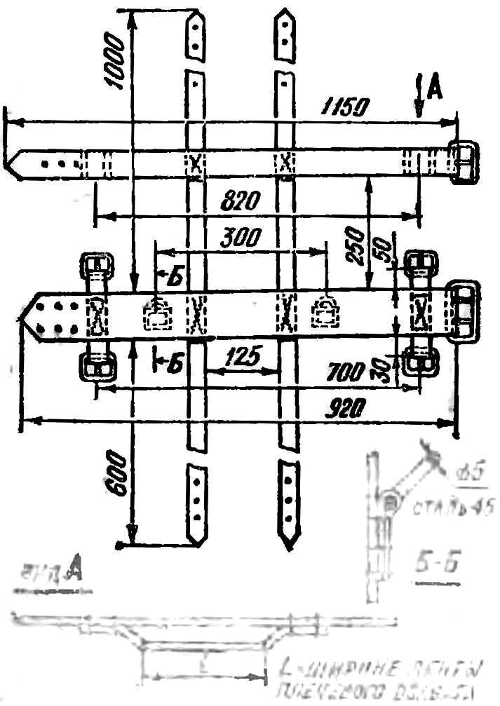
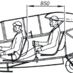
Fig. 3. General view and details of a homemade suspension system, allowing for both vertical and horizontal position of the pilot with the growth of 176 cm and weight 70-80 kg.
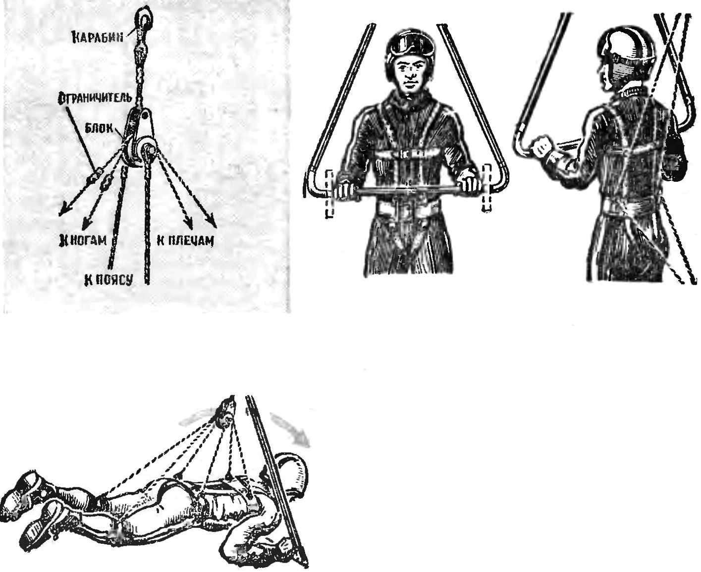
Fig. 4. The scheme is simple pendants that allow the change of body position of the pilot in flight.
Carabiners and webbing harness system is to have one reliable striker (the latch) that allows uncoupling in any position in not more than 2 s.
After Assembly of the frame members is mounted a mast and is determined by the length of the upper cable stretch, which can specify the frame transverse to V and raising of the tail section of the keel at an angle of 5-7°. The lower stretch marks are set so that the steering linkage was tilted forward at about 7-10°.
The center of gravity of the apparatus should coincide with the suspension point of the pilot. This point is determined by the glider hanging from the ceiling. The well-ambulancewoman hang gliding theoretically and practically, it becomes possible to flight from the cast control knob (in calm air).
(Continued. Beginning at No. 4, 1977)
A. DELIVER
Recommend to read
 SCHOOL OF AIRCRAFT (PART 4)
AIRPLANE FOR TWO. Use of a low powered engine in a two-seater suggests several options of its aerodynamic layout. If not enough power, you can increase the load-bearing properties of the...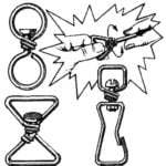 HANG FROM NAIL
Sometimes to connect two devices or articles required joint called a swivel. It provides independent rotations of one part relative to another. The swivel is often used in conjunction...