
In the journal “Modelist-Konstruktor” No. 2 for 1989, material by A. Baklansky from Kremenchug, Poltava region, was published about a micro mill that he designed for his household.
This publication prompted me to also make a similar unit for the same purposes. However, the productivity of A. Baklansky’s device did not suit me — by that time there was already a lot of livestock on the farmstead, and I also planned to increase the number of animals and poultry. Therefore, right away, still “in the rough estimates,” I conceived to make a more powerful mechanism.
Most of the work on manufacturing the unit is welding; there is little machine work, and factory-made parts are also used.
The main components of my mill, as in other similar units: frame-stand, housing, hopper, working organ (rotor with hammers) and electric motor.
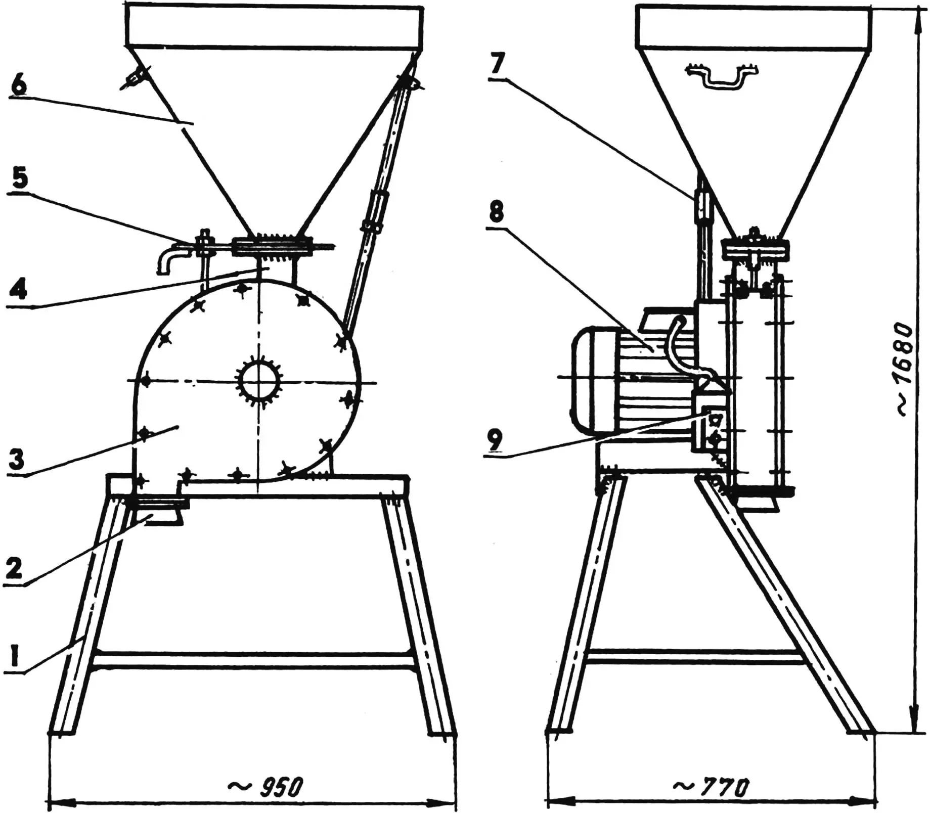
1 — frame; 2 — discharge pipe (St3, sheet s2.5); 3 — grain crusher housing (fan housing); 4 — throat; 5 — gate valve; 6 — hopper (St3, sheet s2.5); 7 — support (pipe 1/2″); 8 — electric motor (N = 7.5 kW); 9 — control unit
The electric motor with a power of 7.5 kW, 3000 rpm, operates from a 380 V network. An automatic circuit breaker rated at 16 A is used in the motor connection circuit to the network. The powerful electric motor also ensures high productivity: there’s no point in stretching out the time for this work — the pleasure from it is below average.
First of all, I welded a frame-stand with a height slightly more than the length of a standard bag, and on top of it (with flanges inward, that is, facing each other) I welded a pair of L-shaped brackets. The four frame posts are made from one-and-a-half-inch water pipes, three lower cross members and two upper ones — from 30×30 mm angle. The brackets are made from 70×70 mm angle. To give them an L-shape, I made a cutout in the shape of a rectangular isosceles triangle in one of the flanges, then bent the workpiece and welded the joint at the cut location. For rigidity, I welded gussets from 2.5 mm steel sheet in the corners of the brackets. The distance between the brackets is according to the size of the electric motor feet. In the lower flanges of their horizontal branches, I made corresponding holes for mounting the electric motor according to the holes in the feet.
I tack-welded the housing to the vertical branches, directing its discharge pipe downward and ensuring the coaxiality of the central hole of the housing with the electric motor shaft. To do this, I put a technological bushing with an outer diameter of 30 mm on the shaft and aligned it with the hole in the housing. The housing-shell (volute) is from a decommissioned fan of a steam installation. I removed the impeller from it as unnecessary, and welded up the suction window of the removable side panel, overlapping it with a patch made of 2.5 mm thick steel sheet. The side panel is attached to the shell with thirteen M6 bolts.
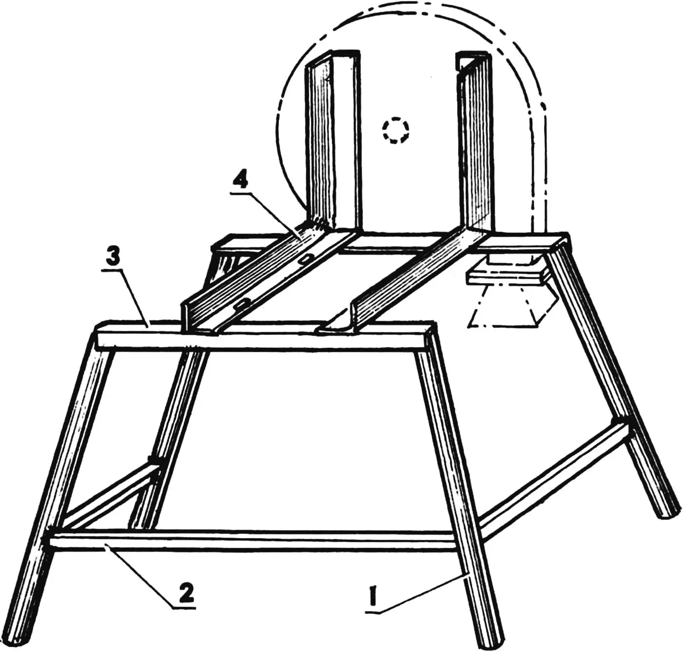
1 — leg (pipe 1 1/2″, 4 pcs.); 2 — lower cross member (steel angle 30×30, 3 pcs.); 3 — upper cross member (steel angle 30×30, 2 pcs.); 4 — bracket (steel angle 70×70, 2 pcs.)
In the upper part of the housing shell, I cut a window for the hopper throat measuring 90×50 mm, with one of its short sides located above the axis of the electric motor shaft (and rotor). Along this side, across the full width of the shell, I welded a small guide platform-visor at an angle toward the window. Here, from the inside, I covered the opening of the discharge pipe from the visor to the edge formed by the pipe wall and the shell with a removable sieve, attaching it with two M8 bolts at each end to the shell. I positioned the sieve mesh along the arc of the shell circumference. I equipped the opposite half of the shell with “decks” — ribbed (on one side) cast iron plates. I used “decks” from an industrial mill — selected from old ones that were more or less unworn. But they didn’t fit the dimensions for my crusher: too wide and long with a large bend radius. Therefore, I had to break them into parts, and from the parts cut out small good segments 94 mm long so they could be laid along the circumference of the shell. Before installation, I drilled two holes for M6 bolts with countersunk heads in each piece (“deck”). Then, placing oak spacers between the “decks” and the shell, I attached the parts to the latter with M6 bolts, having previously drilled corresponding through holes, using each “deck” as a jig. As a result, half of the shell was lined with “decks.” I tried to maintain the distance between the ends of the hammers and the tops of the “decks” within 3 — 4 mm. Over time, the “decks” wear out (not from grain, but from hard impurities: even nuts and bolts can get in there), and the maximum allowable gap is about 10 mm.
I welded flanges to the throat and discharge pipe for connecting the loading hopper to the first, and the discharge tip to the second. I welded corresponding flanges to the hopper and tip. All mentioned parts are made from the same material (2.5 mm thick steel sheet). I drilled the bolt holes in the flanges by assembling the flanges into a pack and slightly tack-welding one part to another.
At the top, I welded low vertical rectangular border-edging to the hopper walls around the perimeter on the outside, and on the sides — a pair of handles bent from steel rod. Between the hopper and throat, I installed a gate: two longitudinal plates with a damper between them. In the damper, I cut a guide groove and a window measuring 90×50 mm (the same as in the shell) to regulate the grain feed from the hopper to the crusher. Between the hopper and the crusher housing, I installed a detachable support from a half-inch pipe.
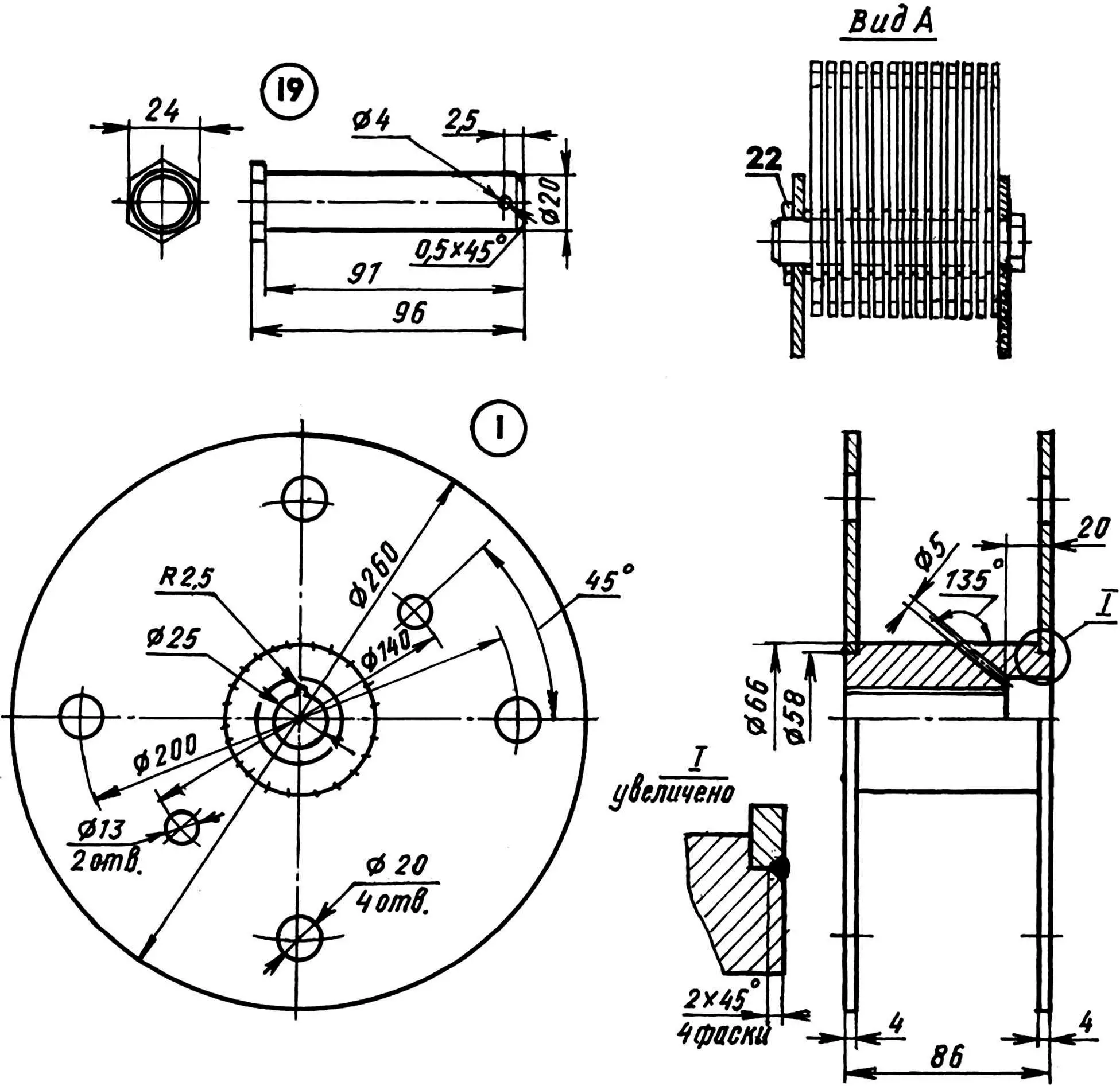
The most critical and complex component in my crusher is the rotor-coil with hammers. The hammers are standard, taken from a serial product, and the rotor is homemade, welded, in the shape of a coil. I turned the coil bushing from a steel blank with a diameter of 70 and a length of about 180 mm. Such length is necessary so that the workpiece can be clamped in the machine chuck and the part can be turned without reinstallation. I made the keyway in the bushing in the following way: I inserted a suitable (according to the hole diameter) steel plug into the hole and at the joint of the parts, with a drill with a diameter equal to the width of the keyway on the electric motor shaft, I made a hole. After that, I knocked out the plug from the bushing.
I made the disc-cheeks from 4 mm thick steel sheet, making in each of them, in addition to the necessary holes (one — for the shaft and four — for the hammer axes), two more with a diameter of 13 mm to connect a puller (for repair) with bolts, installed them on the recesses at the ends of the bushing and welded them. I turned the pins from a suitable hexagon, the washers — from “round stock.” The washer thickness is the same as that of the hammer — 3 mm. After that, I assembled the unit, alternating washers and knives when installing them in 13 sets on each pin in the rotor. At the same time, on one pin I started the assembly with installing a washer, and on the next — with installing a knife. I secured the pins with knives and washers in the rotor with cotter pins.
I mounted the rotor directly on the motor shaft and tightened it with an M12x1.25 screw with a washer, screwed into a previously made corresponding hole in the end of the shaft. I secured the screw itself in the following way: from the center of its head at an angle of 45° to its plane, I drilled a hole with a diameter of 5 mm with its continuation into the bushing body, and then inserted a piece of electrode wire into the hole. After installing the working organs in the housing, I closed it with a cover.
I initially planned the rotation of the rotor with hammers counterclockwise (along the “volute” path — the visor was also welded on the other side of the window). But when emptying the hopper, part of the grain flew back out of the chamber through the hopper in different directions. This disappointed me. I began to look for the cause and a way out of this situation — I changed the direction of rotor rotation by simply swapping the motor power phases, rewelded the visor to the other side of the window, and things went well. Even when you throw a handful of grain into an empty hopper — it is sucked into the chamber without problems and completely processed.
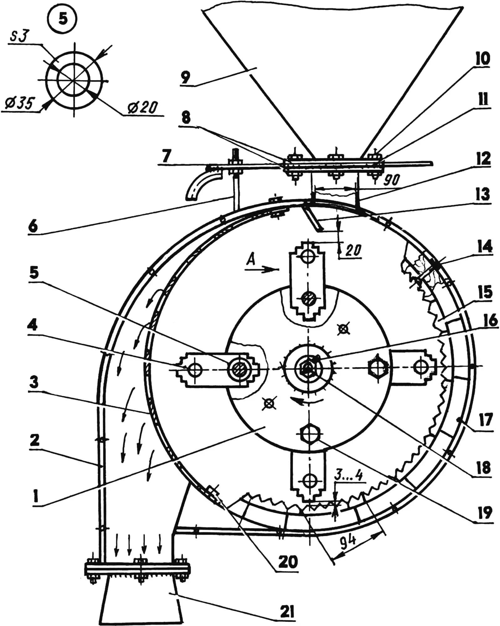
1 — rotor (steel 45); 2 — housing (from industrial fan); 3 — sieve (from serial mill); 4 — hammer (from serial mill, 52 pcs.); 5 — washer (steel 45, round Ø35); 6 — gate valve travel limiter (M14 bolt with two nuts); 7 — gate valve (St3, sheet s2.5); 8 — flanges (St3, sheet s2.5, 4 pcs.); 9 — hopper (St3, sheet s2.5); 10 — M10 bolt (12 pcs.); 11 — spacer plate (St3, sheet s3, 2 pcs.); 12 — throat (St3, sheet s2.5); 13 — visor (St3, sheet s2.5); 14 -— M5 bolt with countersunk head (as needed); 15 — “deck” (as required); 16 — key; 17 — pad (oak); 18 — M12x1.25 screw; 19 — pin (steel 45, hex s24, 4 pcs.); 20 — M6 sieve mounting bolt (4 pcs.); 21 — discharge tip (St3, sheet s2.5); 22 — cotter pin; hole Ø5 in rotor to be drilled together with M12x1.25 screw after mounting on motor shaft.
For crushing grain for livestock feed, I install a sieve with large holes (7 mm). To obtain bread flour with bran, I put a sieve with 2 mm holes. After that, my wife also sifts the flour through a sieve with cells of about 1 mm. The time to change sieves is 15 — 20 minutes.
In the crusher, I grind both large grain (corn) and small grain (even millet), only in the latter case I open the damper by a third. But when crushing oats, I remove the sieve completely — when ground, it turns into a cotton-like mass. On the crusher, I even grind dry clover and hay (for feeding young animals), adding them together with grain. Weeds found in the grain: thistle heads, lamb’s quarters, straw, and whole ears — all this is crushed to pieces and put to use.
I currently load grain into the hopper manually, although there is an idea to mechanize this operation as well.
I determined the productivity of the grain crusher by the volume of poured grain (5 buckets). So, corn is ground in 35 sec, wheat — in 40, barley — in 50, oats — in 1 min 35 sec. If recalculated by mass, it comes out to an average of 1 kg per second.
Over five years of operation, the unit has not let me down. True, I already turned the hammers, and now I’ve repositioned them with the other end.
Another important circumstance — there are practically no losses. When I ground grain at the “collective farm” mill, I got 9.5 bags of crushed grain from 10 bags of grain. Now from the same volume — 11.5 — 12 bags.
V. PRONIN
Recommend to read
 WINGED HYDROPLANE
Speed radioact with a sail-wing. Competitions of radio controlled model yachts are one of the most exciting. Silent glide of sailboats on the smooth surface of the pond, clearly they can... DUO ROLLERS
Original brush two foam rollers used for painting walls and ceilings V. Vakulenko from St. Petersburg. They are located on the shaft so that rotates in contact with each other, the lower...
