We are long-time and regular subscribers of the Modeler-Constructor magazine. For us – as well as for all those who connected their lives with technology – the magazine has always been a kind of information spring, providing life-giving information on issues that interest us. And our interests have always been concentrated on amateur ultra-light aircraft: we have always carefully examined the new products of amateur aircraft designers, and primarily rotary-wing machines – gyroplanes and helicopters.
True, “Modeler-Designer” has practically never had a chance to talk about this kind of technology in recent years. The fact is that amateur aircraft designers extremely rarely undertake the creation of mini-helicopters, and those that ultimately reach “flight” models are literally a few. Nevertheless, all this did not stop us when we finally decided to take on the creation of first a gyroplane and then a helicopter.
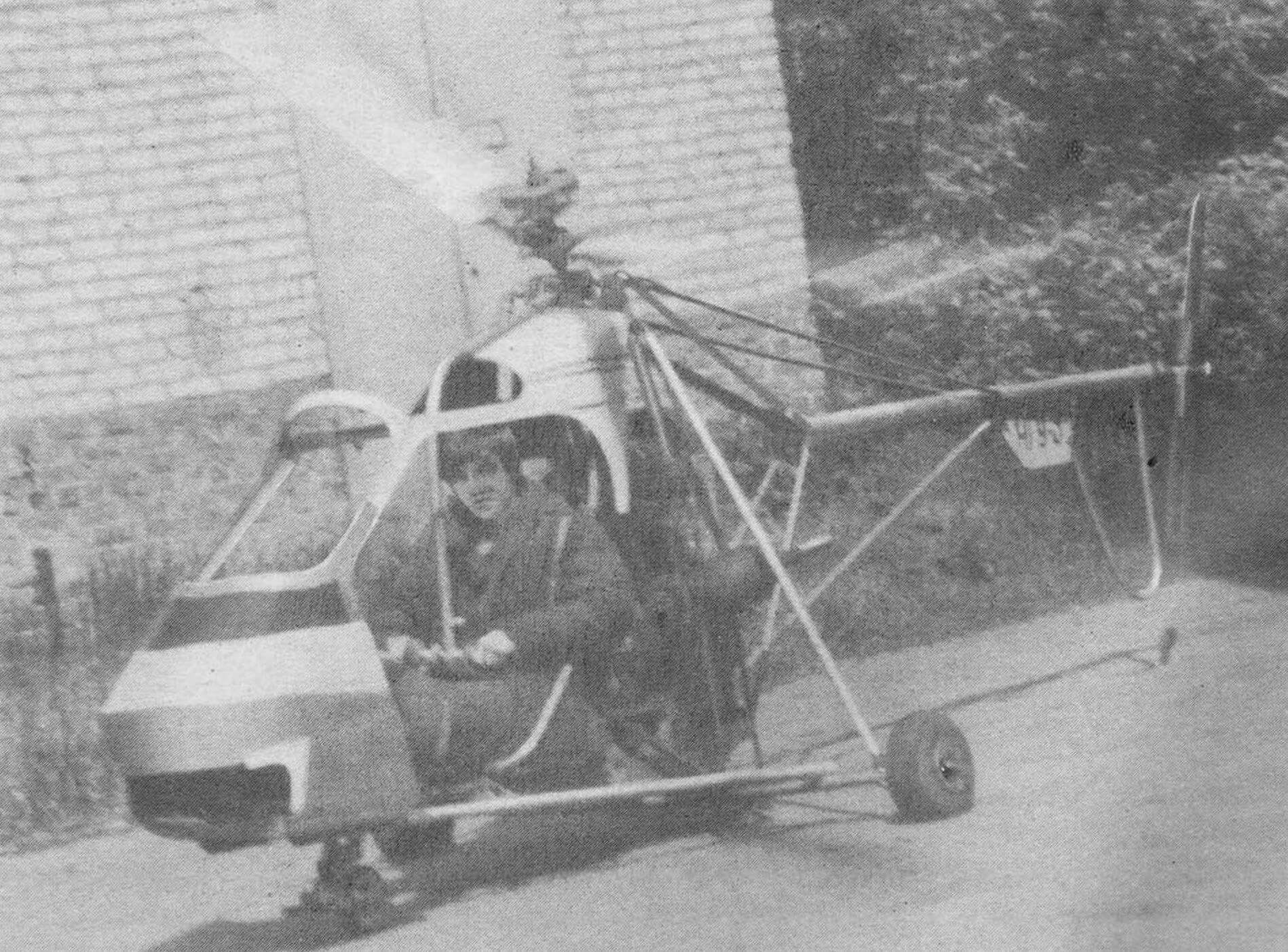
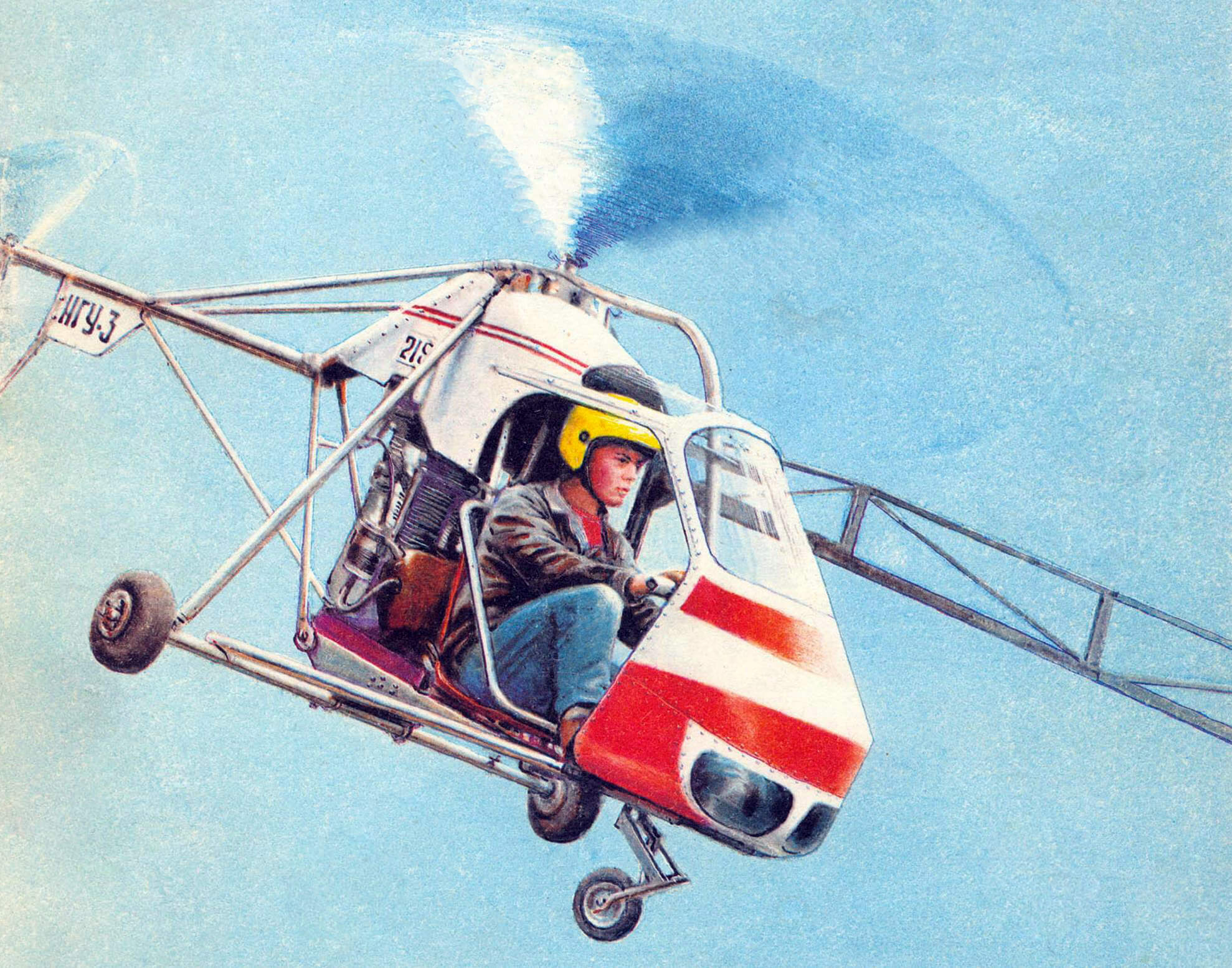
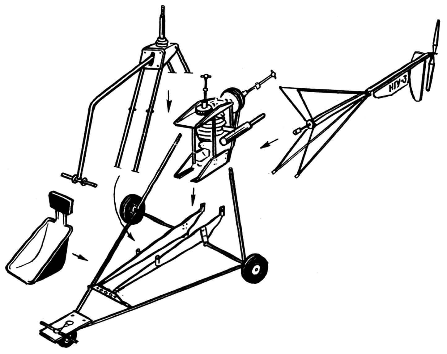
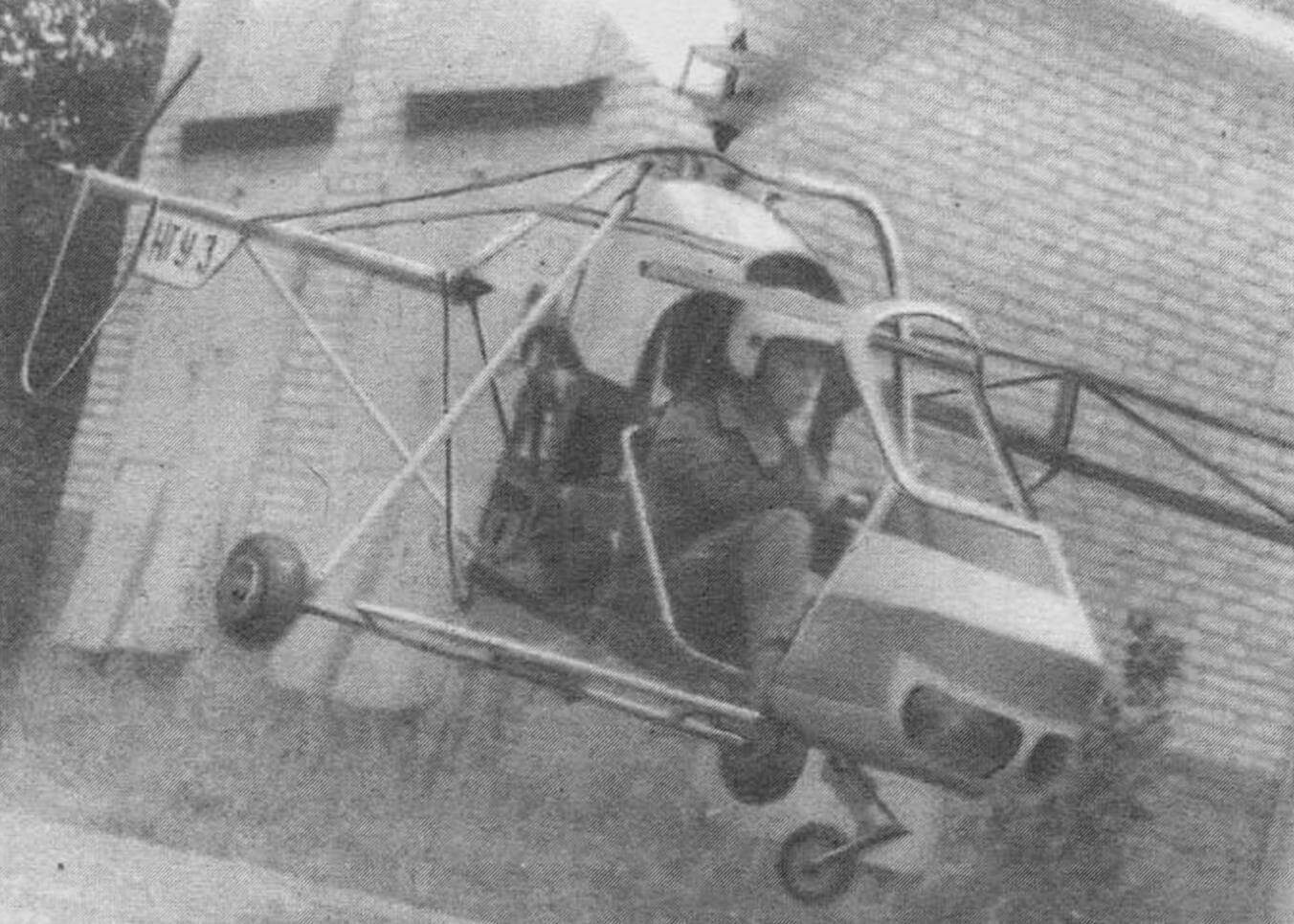
Unfortunately, we were unable to find a reliable and sufficiently accurate method for calculating the main rotor. Therefore, to begin with, we designed a stand for testing rotor rotors. During the manufacturing process, it became more complex, “overgrown” with mechanisms, systems and components – and the result was the NGU-3 helicopter, which can be seen here in the drawings and photographs. All that was left from the stand was the name of our machine, which stood for “Full-Scale Helicopter Installation-3.”
The author of the helicopter project is industrial engineer S. Komissarov. The author of these lines, the head of the aircraft modeling laboratory of the Station for Young Technicians in the city of Likino-Dulevo, devoted a lot of effort and time to creating the machine; Employees and students of the Likino-Dulyovo technical school Li-DAMT also took part in the work, with a completely friendly attitude towards our activities from the management of both the technical school and the city Station for Young Technicians.
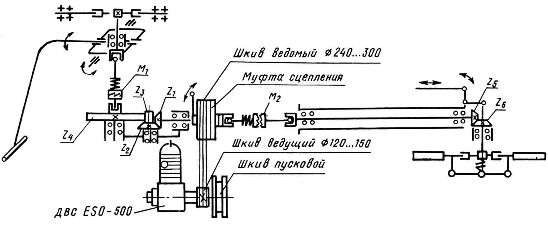
So, a helicopter. We chose the simplest design method – it can be called statistical. In other words, similar helicopters of this type were studied, and based on an analysis of their designs, taking into account the parameters of the power unit we had, as well as the materials and technologies we had, our rotorcraft was developed. By the way, the power unit – the 500 cc ESO-500 engine, without which our work would hardly have made sense, was donated to our group by a local philanthropist, for which a huge thank you to him.
Most of the helicopter components are made independently. And we also “piloted” the car during testing ourselves. She taxied on the ground, and also, using a special stand, made stable approaches to a height of 1…2 meters. The stand was a “well crane” type device that prevented the helicopter from turning and capsizing. Controlling it on the stand made it possible to gradually increase the number of degrees of freedom of the machine and thereby gradually improve the skills of controlling the apparatus. The main thing here was to ensure the safety of this process, since none of us had ever flown a helicopter before.
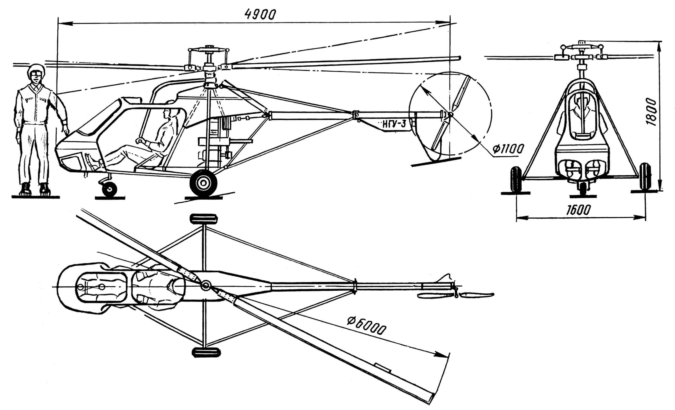
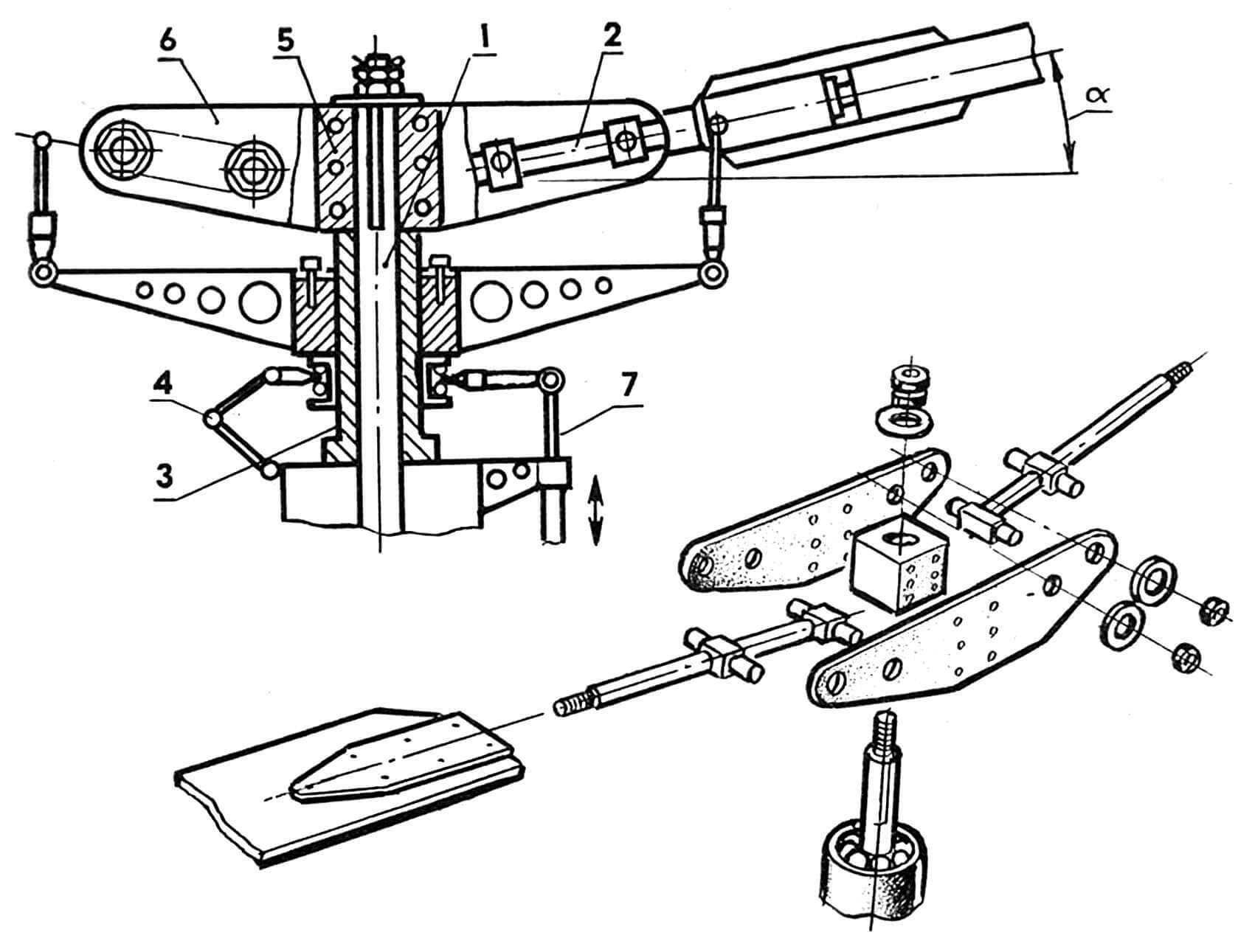
A few lines about the technical characteristics of NGU-3. Thus, the take-off weight of the device is 250 kg; rotor diameter – 6 m; blade profile – CLARK-Y – 10%; engine power – 35 kW (48 hp). The rotor is controlled using a “step-throttle” type handle, changing the direction of the thrust vector is direct. The blade angle control is centrifugal type, located above the main rotor hub. The device is all-metal, assembled from duralumin (D16T) profiles (pipes, “corners”) and sheet material. The supporting blades are wooden (spruce), covered with fiberglass using an epoxy binder. The gearbox is combined, open type. Dry type friction, disc. Torque transmission is via cardan joints.
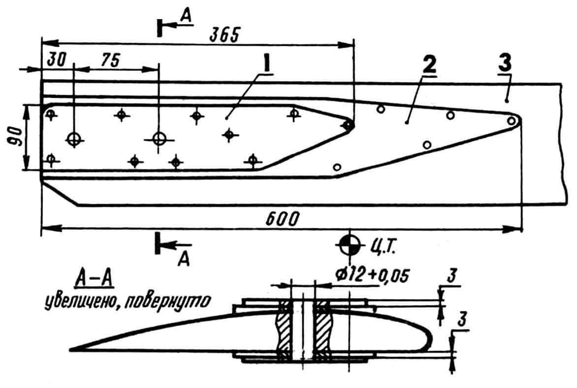
One set of helicopter blades was manufactured using the technology described in the magazine “Modelist-Constructor” No. 3 for 1970, and the other was manufactured using our own, simplified, as we called it, “musical” technology.
A monolithic spruce beam with a certain orientation of layers and the required structure was selected. The bars were dried in a press, jointed, soaked and dried again in a press, jointed again and fixed with varnishes, then profiled, fixed with varnishes and finished again… Then reinforcing linings were glued onto the butt parts of the blades, linings in the area of the tips (and, in fact, the tip itself ), as well as a trimmer unit. Next, the blade was covered with fiberglass using epoxy resin, puttyed, polished and painted. It was even possible to obtain a negative twist of the end sections of the blades.
Balancing the blades along the profile was carried out as recommended in the already mentioned issue of “Model Designer”. Of course, such blades turn out to be quite heavy. However, this is still much better than using decommissioned and cut-off blades from the Ka-26 helicopter, as most of the “gyroplanes” we know do.
We borrowed the open-type gearbox design from a radio-controlled helicopter model and, as practice has shown, we were not mistaken. In general, our helicopter is, in fact, a semblance of such a model, and in the absence of requirements for a significant resource, many problems are eliminated due to the simplicity of the design.
The cardan transmission is designed similar to the drive from the differential to the wheels on the Zaporozhets car. You can’t imagine anything simpler, if, again, you don’t take into account the requirements of the resource.
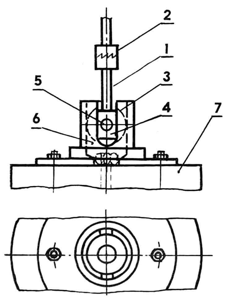
The design of the main rotor hub together with the horizontal hinges looks rather unsightly. But it made it possible to ensure the desired installation and spacing of the blades, as well as to avoid welded joints that could not provide stable strength.
The tail (steering) rotor beam, crutches and braces are made of duralumin (D16T) pipes. The kinematics of the tail rotor drive can cause a lot of trouble: long shafts are always difficult. But we still weren’t tempted by the belt drive and remained faithful to the driveshaft.
The chassis trolley (without nose strut) is from a trike. The trolley is equipped with a duralumin frame and a power unit. The latter is installed on a vibration-damping wooden cushion.
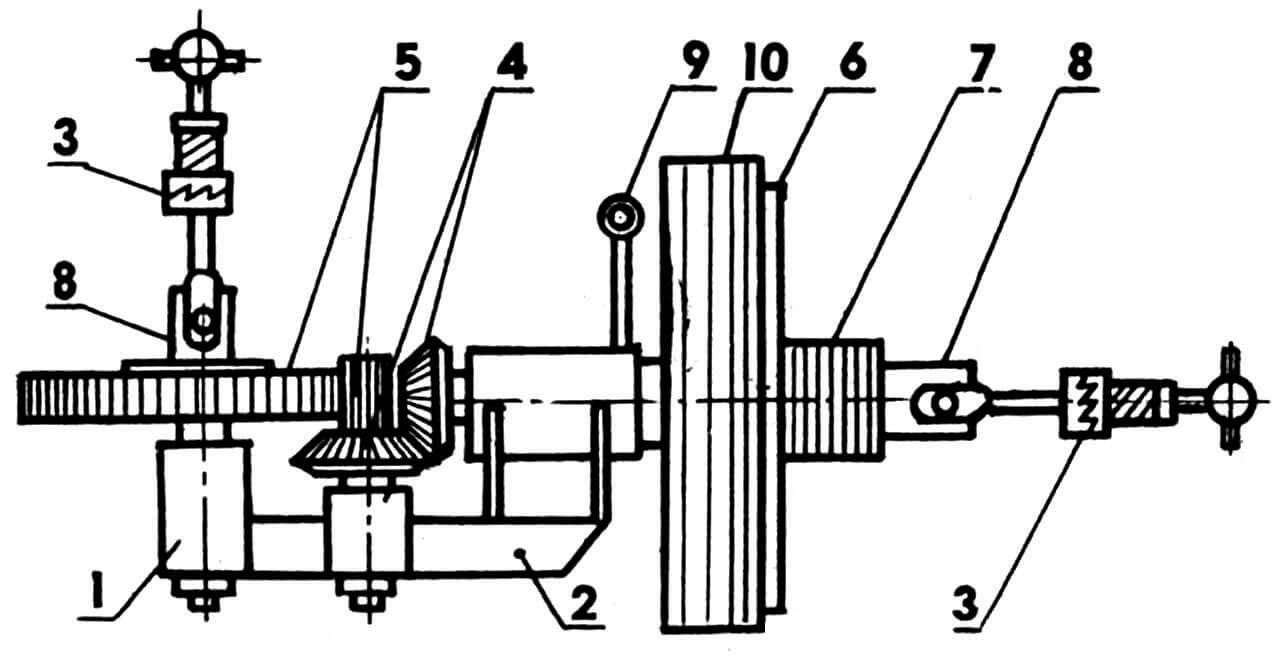
The kinematic diagram of a helicopter transmission is a combination of pulleys and gears. The intermediate bearing supports of the tail rotor drive shaft are installed using rubber pads. The diameters of the pulleys and gear ratios were selected and varied in relation to the characteristics of the main and tail rotors, as well as the parameters of the power unit.
The helicopter test stand was welded from steel pipes according to drawings published in the magazine “Modelist-Constructor” No. 5 for 1983: this issue described a device for training hang gliders to fly. In our case, we used the stand to ensure safety during testing and developing helicopter piloting skills. The helicopter mounted on it can move forward, backward, upward, and also (within small limits) turn around when the tail rotor operates. The pitch angle can also change due to gauching (twisting) of the entire stand truss, since it is flat and does not work in torsion.
It must be said that the use of the stand made it possible to give all the builders of our helicopter the opportunity to acquire the skills to control a rotorcraft without risking the only copy of the aircraft and their own lives.
Alexey SOROKIN, Likino-Dulevo, Moscow region.
Recommend to read
 PRESSURIZATION — “MUSCOVITE”
On the roads of Russia today quite a lot of cars of foreign production. To feel confident in dense traffic and domestic car, sometimes you have to reinvent the wheel. Indeed, the idea of... VAZ-2101 SPORT
About sports "cents", the General public knows not so much. However, "Lada" took part in the USSR championship in road racing in 1972, almost immediately after the start of their serial...
