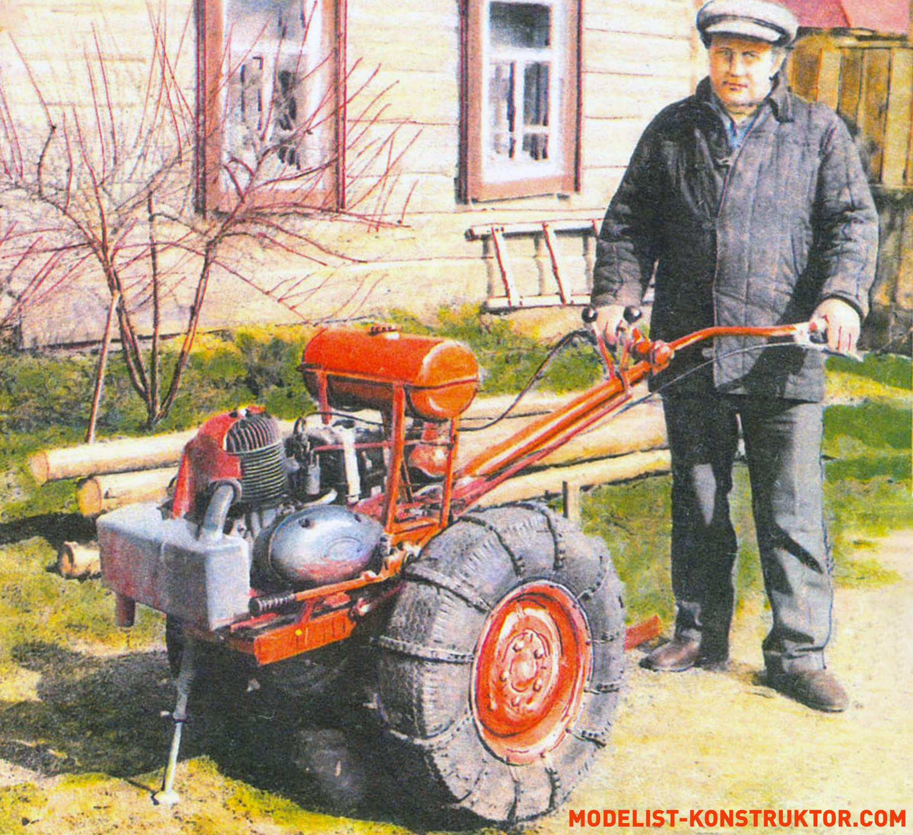
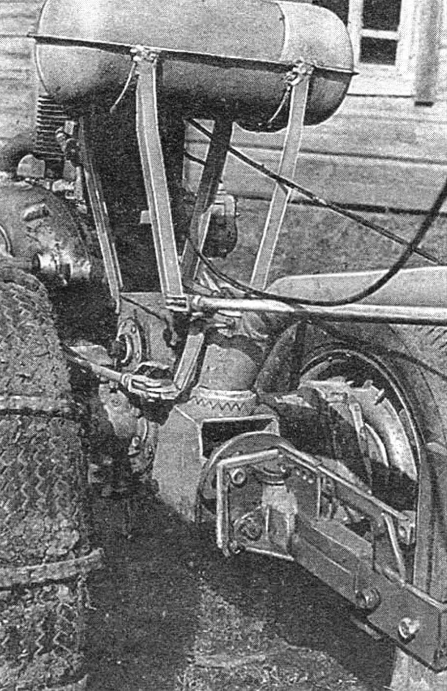
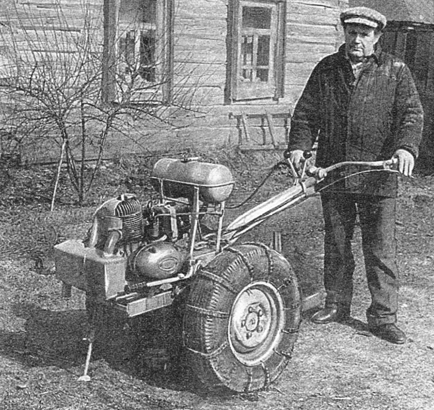
This walk-behind tractor was not created for an exhibition – for work. In the garden, on a personal yard. In order to plow the plot, and spray the trees, and cut firewood, and transport what is needed for the housework… Many options were sorted out before the choice fell on the design, which, as life has confirmed, turned out to be extremely successful: efficient, reliable, beautiful (see. illustrations). And relatively inexpensive.
Of the ready-made purchased components, only the power unit was required (taken from the Tula-200 M, a fairly common motor scooter with high performance characteristics) and the main gearbox from a decommissioned motorized stroller (it is also possible from other equipment that has a reverse and properly “fits in” into the kinematic diagram of the walk-behind tractor transmission).
You will also have to order (if it is not possible to make them yourself) wheel reduction gears, axle shafts and some other parts. But they can sometimes be successfully obtained… at a landfill, where careless business executives take out “industrial trash.” By the way, it’s also easy to find wheel rims there, as well as tires that are unsuitable for high-speed vehicles, but quite acceptable for a hard-working walk-behind tractor. For example, from an M2140 car with 6.45×13” tires. In addition, you will need oil seals, ball bearings (preferably with protective washers) of appropriate sizes, and fastening material.
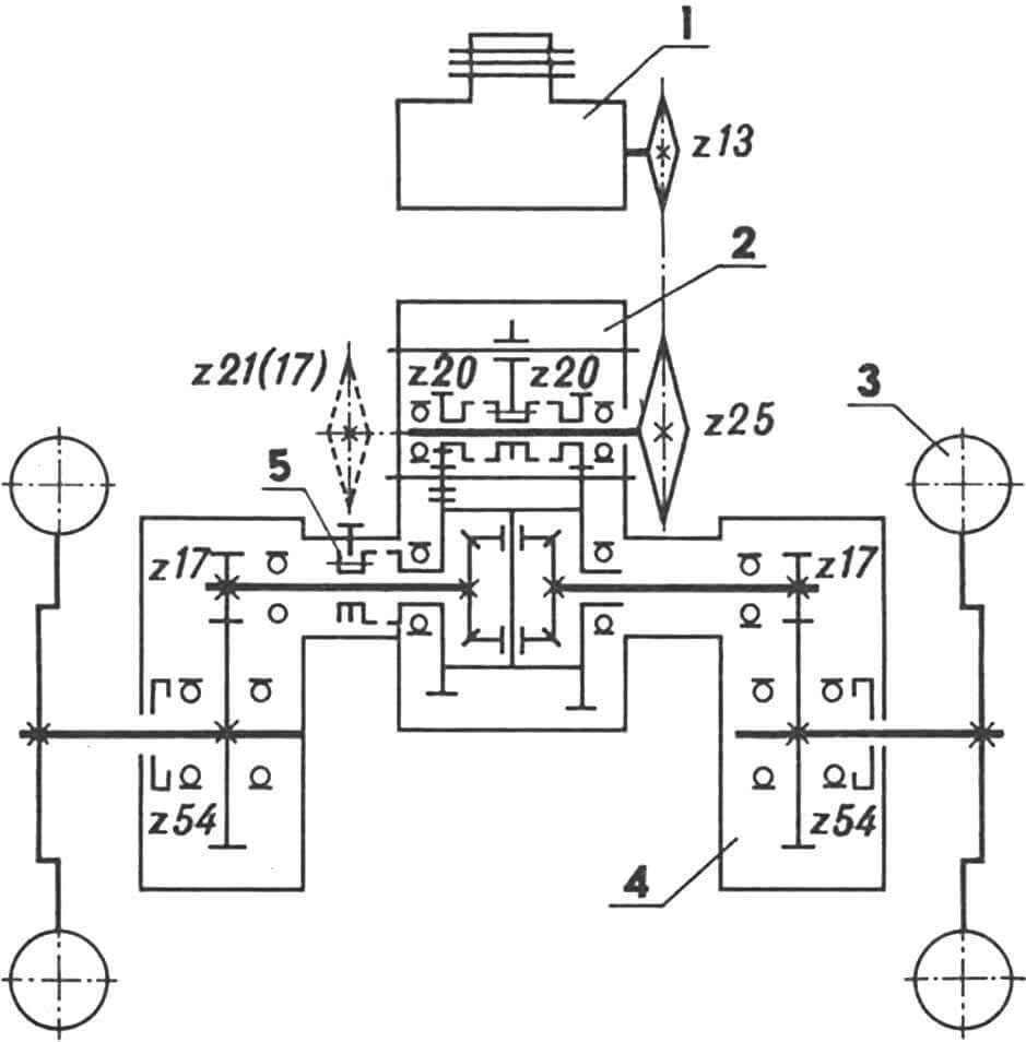
1 — T-200M power unit, 2 — main gear (from a sidecar, with reverse), 3 — drive wheel (from an M2140 vehicle), 4 — wheel reducer, 5 — differential locking clutch.
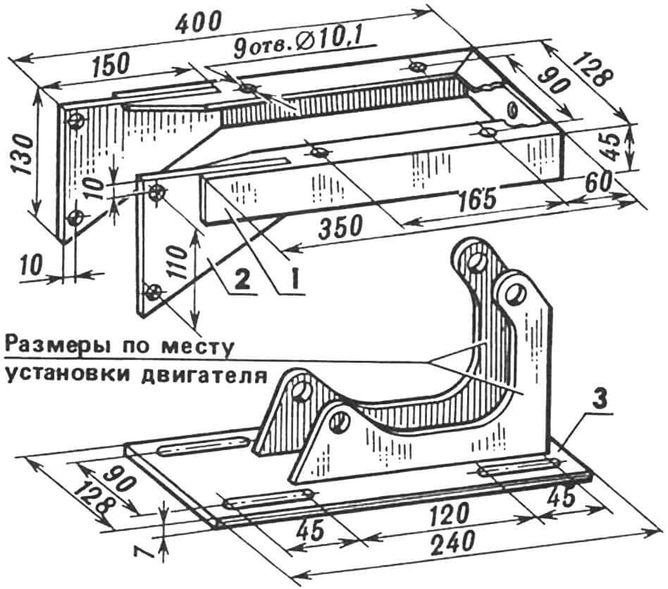
1 — base (welded U-shaped, from a corner 45×45 mm), 2 — welded gusset (Art. 3, 2 pcs.), 3 — engine mounting plate.
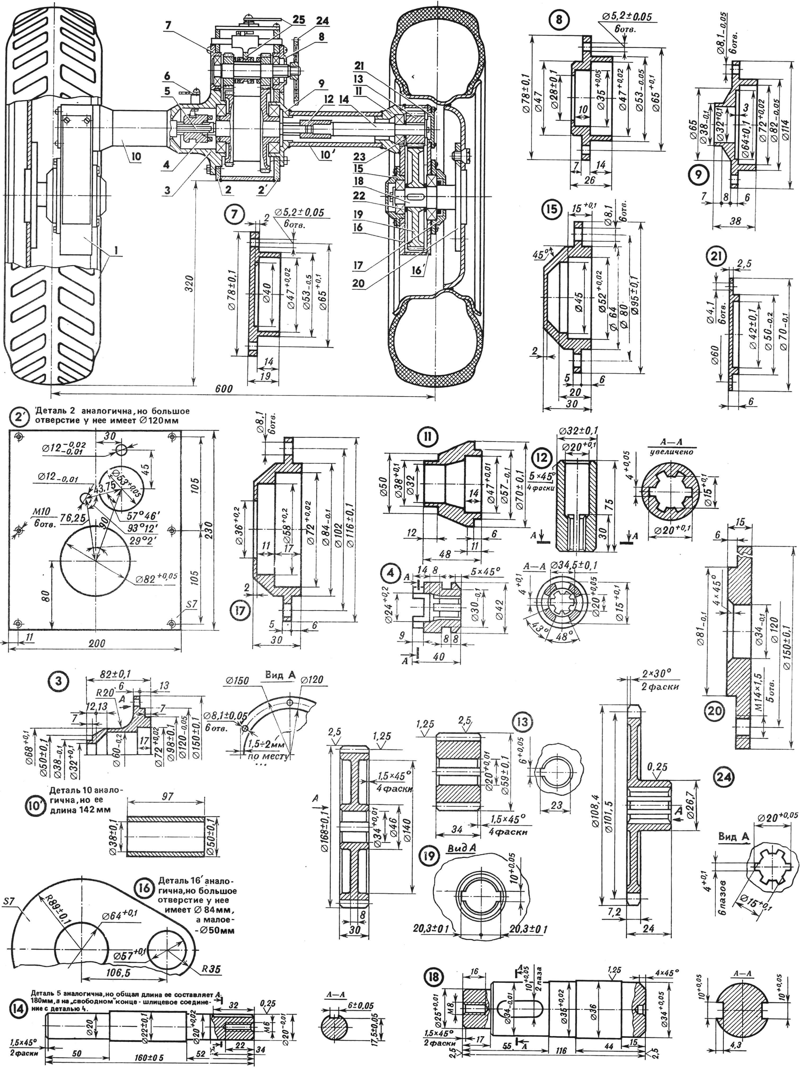
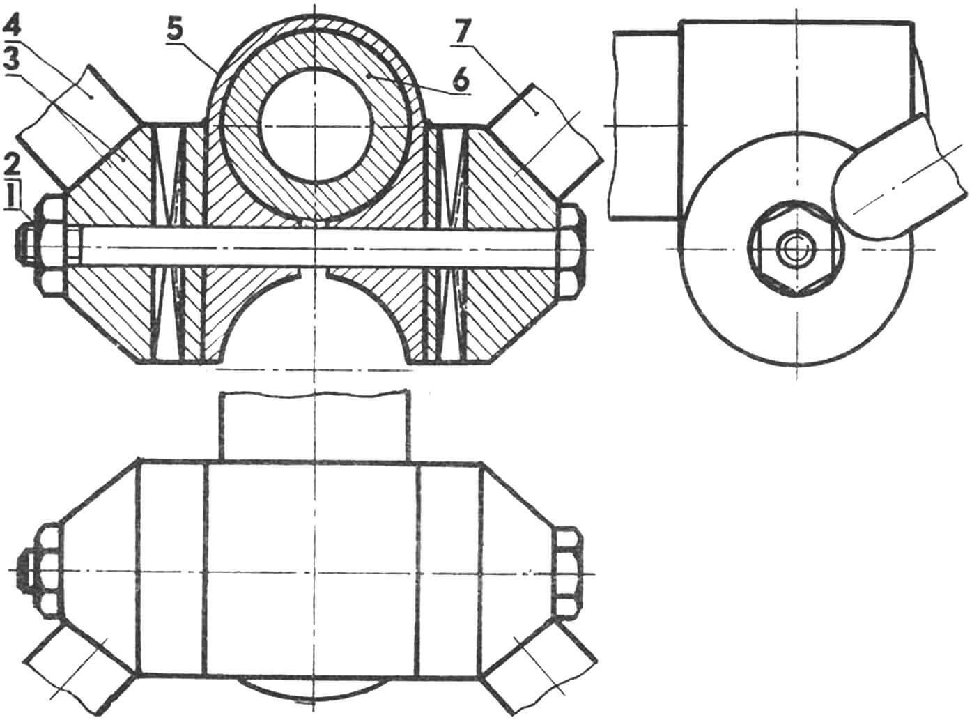
1 — walk-behind tractor wheel assembly, 2 — left GP housing wall (Art. 3), 21 — right GP housing wall, 3 — left cover-casing (Art. 3), 4 — splined locking clutch (Art. 45), 5 – left axle shaft (Art. 45), 6 – locking mechanism, 7 – cover of the bearing assembly of the left main shaft (Art. 3), 8 – cover of the bearing assembly of the right main shaft (Art. 3), 9 – cover – right casing (Art. 3), 10 — left sleeve-casing (142 mm section of steel pipe 50×6), 101 — right sleeve-casing (97 mm section of steel pipe 50×6), 11 — flange-casing ( Art. 3, 2 pcs.), 12 — splined coupling (Art. 45), 13 — cylindrical gear wheel (z17, m3, dа59, b34, Art. 45, 2 pcs.), 14 — right axle shaft (Art. . 45), 15 — inner wheel gear bearing assembly cover (Art. 45), 16 — inner wheel gear wall (Art. 3.2 pcs.), 161 — wheel gear wall (Art. 3.2 pcs.), 17 – cover of the wheel gear bearing unit (Art. 3.2 pcs.), 18 – wheel axle (Art. 45.2 pcs.), 19 – cylindrical gear wheel (z54, m3, dа168, b30, Art. 45.2 pcs.), 20 — wheel disc (Art. 3.2 pcs.), 21 — cover (Art. 3.2 pcs.), 22 — spacer ring (4 pcs.), 23 — spacer washer (2 pcs.), 24 — sprocket z25 of the drive roller chain PR-12.7 (Art. 40X), 25 — gear switching device.
Now – directly about the design of the walk-behind tractor. The main technical solutions here are quite traditional. The engine (see transmission kinematic diagram) is connected by a chain transmission to a differential gearbox (GP from a sidecar). The required gear ratio i=1.92 is provided by sprockets z13 and z25 with a pitch of 12.7 mm. It is advisable to use ready-made ones. Let’s say, from decommissioned equipment. But you can do it yourself using technology described in detail in widely available literature (see, for example, “M-K” 2’86).
The dimensions and shape of z25 are shown in the figure (item 24). Well, the z13 differs, naturally, not only in having almost half the number of teeth, but also in the circumference of the protrusions (59 instead of 108.4 mm), and the diameter of the pitch circle (53 instead of 101.5 mm).
Looking ahead, we will indicate the values of the latter for z21 (17), if you decide to install it (say, for power take-off when operating a walk-behind tractor as a wood cutter, a motor pump, etc.) on the main gearbox input shaft, which in this case must be extended on the left with cutting splines . So: for a sprocket with 21 teeth, the diameter of the protrusion circle should be 92 mm, and the diameter of the pitch circle should be 85.2 mm. If you use a sprocket with 17 teeth, the dimensions will correspondingly decrease to 75.2 mm and 69.1 mm.
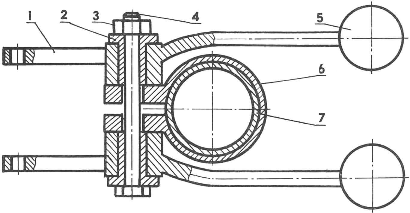
Torque from the differential is transmitted to both axle shafts connected to wheel gearboxes with i=3.18. A reverse and locking mechanism are also provided, which is important for efficient operation and significantly expands the range of use of the walk-behind tractor. As, indeed, is the rod control. The handles are adjustable in height and length, and can be rotated ± 60° in the horizontal plane.
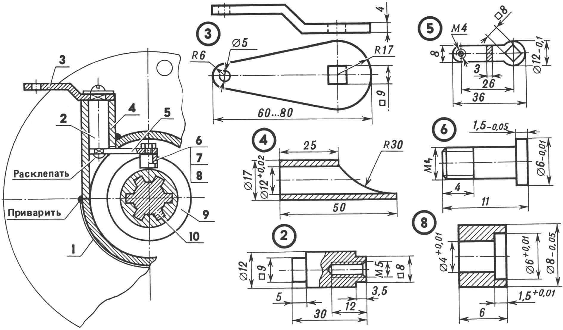
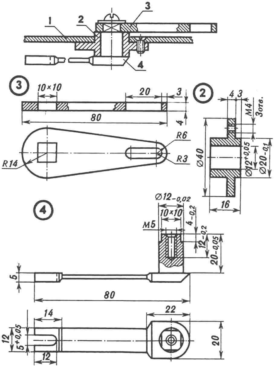
1 — left cover-casing, 2 — shaft (Art. 45), 3 — curved lever (Art. 3), 4 — welded bushing (Art. 3), 5 — straight lever (Art. 3), 6 — axle bolt (Art. 45), 7 — M5 nut, 8 — roller (Art. 45), 9 — splined locking clutch, 10 — axle shaft (left) with a splined end.
The walk-behind tractor frame is welded from a 45×45 mm corner. It is made U-shaped, successfully fitting into the overall technical design of the MB design. A steel plate with risers for mounting the engine is installed on it, like on a skid. The slot-holes in the plate play the role of guides when tensioning the chain drive and at the same time are fairly reliable fastening elements. At the rear of the frame (thanks to the holes in the gussets) the mechanism of the towbar and steering mount is attached using M10 bolts.
Here everything, as they say, is extremely clear: we must take it and do it! Difficulties sometimes arise elsewhere – during the assembly of wheel gearboxes and gearboxes. It’s understandable: it’s a very important operation. It is advisable to perform it in the following order.
The wheel axle (see figure, part 18) is pressed into the central hole of the disk 20. For greater reliability, they are welded together along a 4×45° chamfer.
Then take the bearing unit cover (part 17) and install it in place in the wall of the wheel gear (part 16′), after pressing in the oil seal and placing a cardboard gasket 0.8…1 mm thick. Place this assembly on the wheel axle. Press bearing 80 207 into the seat prepared for it. Set gear 19 to a tight fit. There, where a key placed in a recess on the axle was already waiting for him. As well as the spacer ring.
Move on to bearing 80 205. Press it onto the wheel axle, securing it with a washer and an M8 bolt. Place a cover 15 on the bearing, connected to the “small” wall of the wheel gear.
1 — main gear housing cover, 2 — bushing (Art. 3), 3 — upper lever (Art. 45, heat HRC 40…45).
Now it’s time to move on to the upper part of the assembled gearbox. Gear 13 should be installed there, but an appropriate place must be prepared for it. Therefore, they take the bearing 80 204 and press it into the seat formed by the axle shaft 14 and the flange-casing 11. Well, having first installed a spacer washer and a key, they press the gear 13 itself, securing it with an M6 bolt.
The assembly assembled in this way is connected to the inner (small) wall of the wheel gearbox and the places marked on the drawing are carefully welded. But the walls are not connected to each other, the gearbox is still open. Therefore, they measure the distance between parts 16 and 16′ and, bending a piece of steel tape of the appropriate width, weld the parts of the body into a single whole, making sure that there is a “window” left for pouring AC8 oil and (if necessary) disassembling the wheel gearbox.
But that is not all.
Putting the splined coupling (parts 1 2) on the axle shaft 14, weld them together. Adjust the window cover to its location, secure it with M4x12 screws through a rubber gasket glued to the cover itself with Moment synthetic glue. Now the wheel gearbox can (with good reason) be considered assembled.
The second wheel gearbox, installed on the walk-behind tractor on the left (downstream) side, is assembled in a similar way. As, indeed, the main gear. Although the latter, to be absolutely precise in everything, has its own characteristics. Specifics? Please!
When “adjusting” the left cover-casing (part 3) to the left wall of the GP case and installing part 7 in its place (meaning holes with a diameter of 120 ± 0.05 mm and 53 + 0.05 mm, respectively), they are “seated » on a gasket made in the shape of a figure eight (one for both holes). The covers in question are then secured with bolts.
And now they move on to the main gear input shaft. It is pressed in with gears and a reverse clutch put on (on it). As they say, it’s “inconvenient,” but there’s nothing you can do: you have to! Then the differential (assembled) is pressed in, as well as the right wall with covers (parts 8 and 9). Having measured the distance between the right and left walls of the GP casing, corresponding plates are made according to these dimensions and welded to the side walls.
But the work doesn’t end there. Therefore, they install a roller with a shift fork (see illustrations), an intermediate shaft with a reverse gear. Attach the cover with M4 screws, having previously assembled the stroke switching mechanism itself. And only then can the main gear be considered assembled.
All that remains is to attach the gearboxes, having first put on the bushings-casings: the short one (part 10) on the left side, and the long one (part 10′) on the right. They are welded respectively with parts: 3 and the flange-casing, located on the left side of the GP, and 9, 11 – on the right. Secure the covers covering the small gear of the gearbox. And that’s it: the walk-behind tractor bridge can be considered assembled.
Speaking about the features of working with a GP, it should be noted that even an excellent factory design still has to be adapted specifically to the walk-behind tractor. In particular, make a new axle shaft (see part 5 in Fig.) with a spline part extended by 30 mm: a place for the differential lock clutch. It turned out to be advisable to grind off the shoulder on the intermediate shaft of the GP to a diameter of 14 mm.
It was also necessary to change the gears of the main drive input shaft so that each of them had not 25 teeth, but 20. This was dictated by the need to increase the gear ratio and so that the input shaft could be easily removed through any hole in the housing wall – in case of repairs or preventive maintenance of the walk-behind tractor .
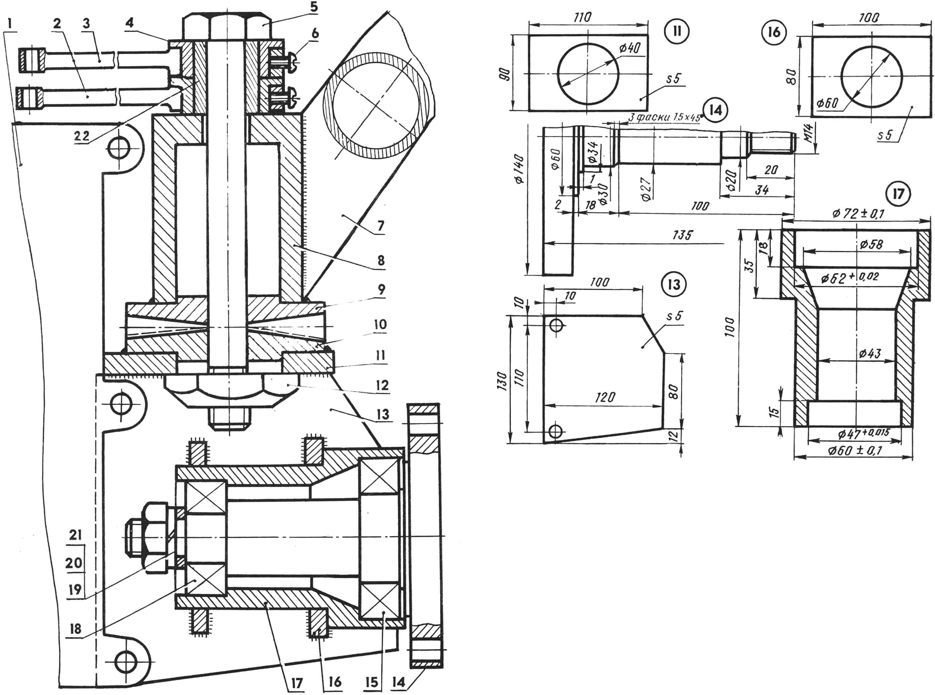
1 — main gear housing, 2 — shift lever, 3 — gear shift lever, 4 — bushing (2 pcs.), 5 — bolt-axle, 6 — mortise screw (2 pcs.), 7 — steering rod (piece thick-walled steel pipes), 8 — support sleeve-sleeve, 9 — coupling coupling with a V-shaped tooth (rotating part), 10 — coupling coupling with a V-shaped tooth (fixed part), 11 — support plate, 12 — shaped nut, 13 — side plate (2 pcs.), 14 — rotary hitch, 15 — radial bearing with protective washers 80206, 16 — axlebox mounting plate (2 pcs.), 17 — coupling axle box, 18 — radial bearing with protective washers 80204, 19 — spacer washer, 20 — G rover washer, 21 — M14 nut, 22 — bronze bushing.
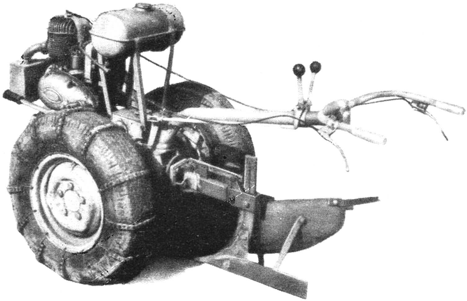
The walk-behind tractor uses a single-horse plow, which has a “floating” mount and is adjustable for the thickness of the captured layer (plowing depth), as well as for the angle of inclination (see illustrations). It is possible to equip the motorized assistant with soil-cultivating implements and other designs. Including homemade ones, the drawings and descriptions of which were repeatedly published on the pages of the Modeler-Constructor magazine. This is a special rotary plow (“M-K”, No. 5’90), and a hiller, the working element of which is made in the form of a pointed paw (No. 4’85), and a disk cultivator (ibid.). As specially conducted tests have shown, the mower and other trailed implements, the designs of which were published in No. 6, 1985, also aggregate well.
Of course, it would be nice to expand the capabilities of the walk-behind tractor even further. And this desire is possible. It is only necessary to provide our motor assistant with a special device for power take-off, having machined a slightly different GP input shaft than in the original version, with a splined part and threads on both ends: after all, in this case it is easy to use mounted implements. For example, the same circular when preparing, say, firewood for the winter, etc. Remaking the input shaft will entail the production of not one bearing cover, but two, absolutely identical. The second is to replace part 8, which does not have a central hole (see publication in the previous issue of the magazine).
1 — bolt-axle, 2 — nut, 3 — coupling with V-shaped small teeth (2 pcs.), 4 — left handle, 5 — clamp, 6 — steering rod with a plug at the end, 7 — right handle.
1 — gear shift lever, 2 — bushing (2 pcs.), 3 — nut, 4 — bolt, 5 — plastic ball (2 pcs.), 6 — clamp, 7 — steering rod.
A few more words about the trailed trolley, the presence of which turns the walk-behind tractor into a vehicle with an articulated frame, capable of moving at speeds of up to 20 km/h. The design can, of course, be any, as well as the dimensions. It would be better, apparently, not to get carried away by gigantomania. Let’s say, with rather modest dimensions (body length 1000 mm, width 950, and side height 300 mm), such a cart is capable of transporting cargo weighing up to 400 kg. The sides and bottom are easiest to make from wood; the tailgate is folding. For the carrier (drawbar), a simple design made from sections of water or gas pipes is suitable. The seat can be borrowed, for example, from an old moped. It is better to install it in such a way that you can control your “vehicle” without much stress. And equip the wheels of the trolley with a foot brake.
Need a watering device? No problem either. We advise you to use a homemade development published in No. 7 “M-K” for 1990. The productivity of such a pump is 10…12 m 3 /h. And the power is quite enough to supply water through a hose at a distance of up to 150 m. Moreover, the pressure of the stream is such that water from the watering hose can “fly” 15 meters or more.
In short, there is something to think about. After all, the main thing is to have a reliable motorized assistant, and it can be equipped with any trailed and mounted implements.
TECHNICAL DATA OF MOTOR BLOCK:
Dimensions, mm 1800x760x1000
Track (changeable by turning the wheel 180°), mm 600/750
Ground clearance, mm 320
Engine – single-cylinder, two-stroke T-200M
Engine power, hp 8
Speed range when plowing, km/h 1.8—6
A. YAZYKOV , Kursk region
Recommend to read
 “TIT” IS IN YOUR HANDS
"Suli's not pie in the sky, give it to the bird in hand..." So says an old Russian proverb. Don't know whether it was guided by the famous Lithuanian designer Bronis Oszkinis, creating...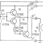 ELECTRONIC VOLTAGE REGULATOR
Many motorists available means, to improve the performance of various components of your machine. Considerable help in providing them electronics. To take at least a variety of...
