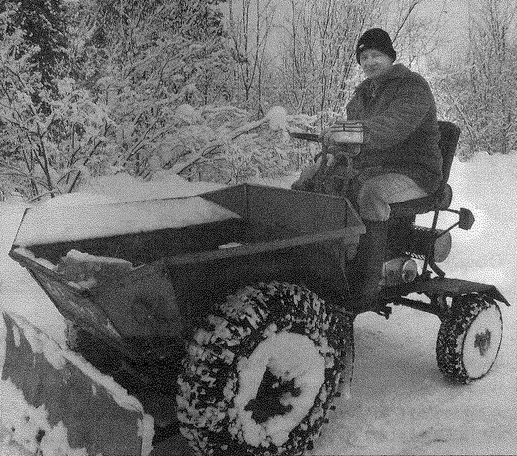
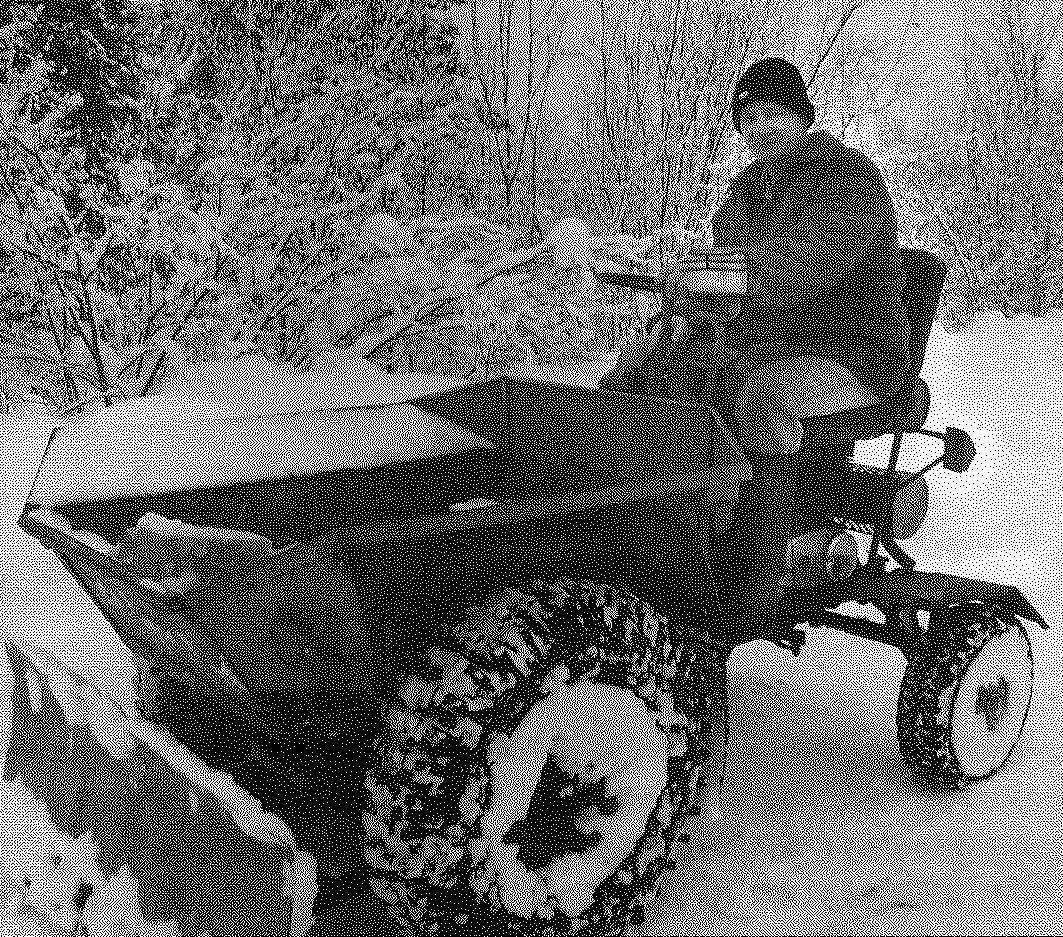
 I’ve been a longtime reader and a regular subscriber of the magazine “modelist-Konstruktor”. For nearly forty years, not only got acquainted with the machines and mechanisms for designers and fans, but also created their. So we can classify themselves as a cohort of “DIY” with the experience. Built mainly teleoperative and transport equipment (walking tractors to monster trucks). Something from a previously created dismantled or altered, some sold, and some exploit until now, for example, a mini-tractor (or rather, self-propelled chassis), which design and present to readers.
The chassis is designed for transportation of various goods for subsistence farming (as in its own body, and towed the trailer), and in winter for snow removal with forward-mounted front dozer blade.
Description construction starts with the frame. She cooked mostly from steel plumbing pipes with round cross-section. In plan (top view) frame has the shape of an elongated trapezoid with a large base ahead.
The base of the frame consists of two straight parallel longitudinal members made of a pipe with outer diameter of 42 mm and a wall thickness of 3 mm. Of the same pipe made and a pair of front cross members: the first solid and the second of three parts. Rear side members are connected by three short cross pieces. Other frame parts are made of thinner pipes with external diameter of 32 mm and a wall thickness of 2.5 mm. Auxiliary elements (racks, strut, struts, etc.) — from a round pipe 22×2 mm Various brackets for mounting units and parts made of a suitable rolled sections.
For the most part they welded to the frame in place during layout of units and mechanisms of the structure, and therefore in the drawing frame not shown.
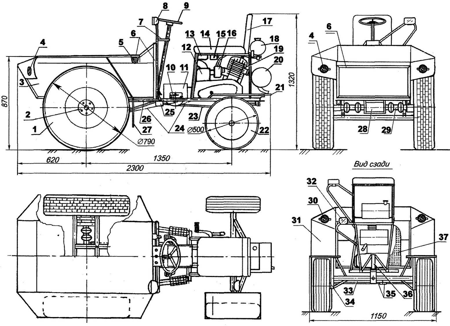
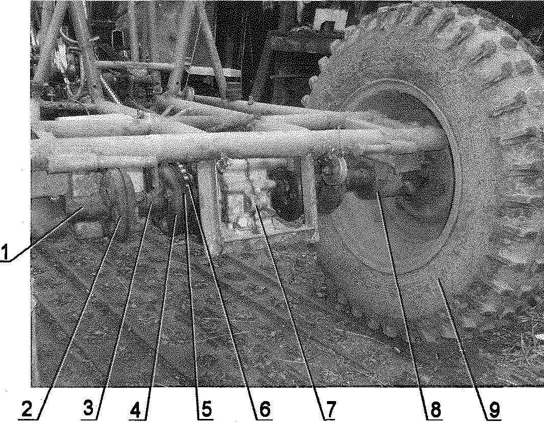
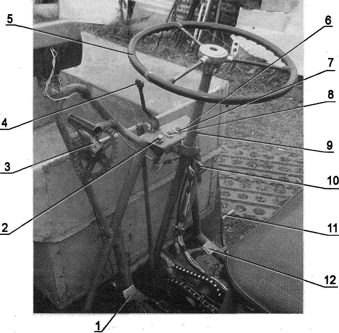
layout of the units and units, motohashi:
1—front driving wheel (on the car UAZ modified with a “checkered” tires, 2); 2—wheel hub (from a UAZ ); 3—trim body (sheet s1); 4—white reflector (2); 5—yellow reflector (2); 6—body frame (area No. 2.5 and No. 3); 7—instrument panel; 8—beam (tractor); 9—wheel; 10—intermediate chain reducer; 11—a casing of the intermediate shaft of the chain transmission (sheet s1); 12—air filter; 13—tool box; 14—seat; 15—the ignition coil; 16—carburettor; 17—seat; 18—tank; 19—engine (from a motorcycle “IZH-Planeta-3”); 20—a muffler (from a snowmobile “Buran”); 21—rear wing wheel (steel sheet s1, 2); 22—rear driven wheel (sidecar FDD, 2); 23—longitudinal steering rod; 24—chain; 25—steering gear (motorized FDD); 26—frame; 27—front wheel splash guard (rubber s5, 2 PCs.); 28—main gear—reversedorder (cargo scooter “Ant”); 29—axle shaft (CV-joints from sidecar, 2); 30—a red reflector (2); 31 — front inner fender (steel sheet s1, 2); 32—rear lights (purchased product); 33—rear axle; 34 front steering blocks (channel No. 5, 2); 35—tie rods; 36 bracket mount engine mounts—motor mount (2 pieces); 37 system forced air cooling of the engine.
Chassis mini-tractor is removed from the blade and body.
Between the front cross members at the ends are welded on two brackets made of U-shaped profile 50x25x50 mm. To them are bolted to the hub of the front wheels. To the side members by means of welded fins (25×25 area) of a box-frame for mounting the gearbox main gear.
To the rear cross members are welded to the brackets of the U-shaped profile for a suspension on the rear axle, and locking brackets that allow you to use the crossmember from the rear, the two lugs forming a drag hook.
On top of the frame (about the middle of its length) is fixed by welding the steering rack with a bracket for the headlight and in the back — the legs and frame the seat and its backrest. The upper (horizontal) part of the steering rack — jumper is made from a wide channel — it is your dashboard. More below the front part welded on the hanging rack with moulded eyelets (reinforced with braces), to which is suspended a dozer blade.
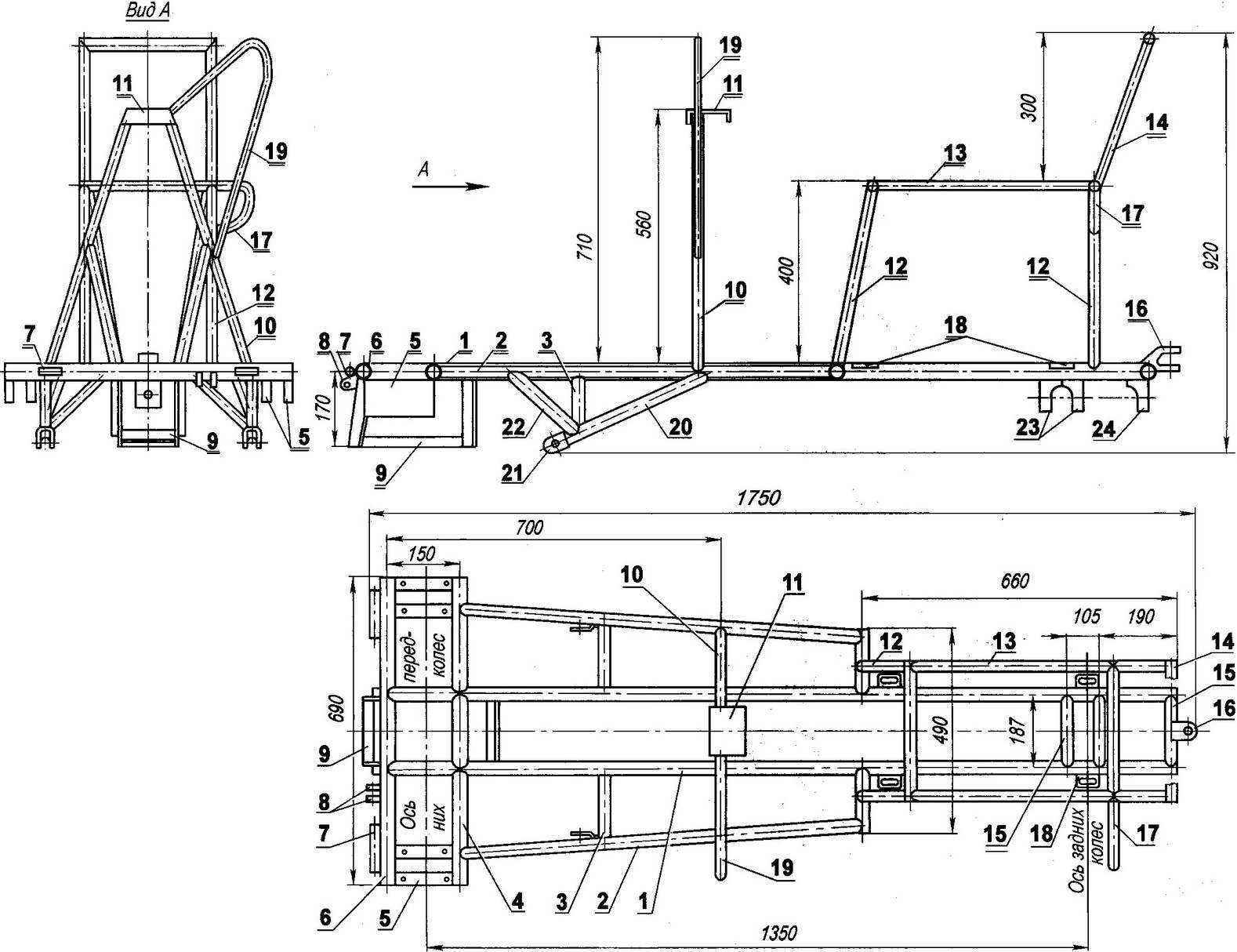
Frame (material steel):
1 —spar (tube 42×3,2pcs.); 2 — longitudinal beam (pipe 32×2,5, 2); 3—cross brace mounts to the blade (tube 32×2,5, 2); 4—second front cross member (tube 42×3); 5—bracket fixing hub (U-shaped profile 50x25x50, 2 pairs); 6—the first front cross (tube 42×3); 7—bushing suspension body (tube 22×2, 2); 8—lugs installation of the cable pulley of the lifting body (sheet s5); 9—drawer-frame gearbox (area 25×25, 2); 10—steering rack (pipe 32×2,5); 11 —jumper stand—instrument panel (roll-formed channel No. 10); 12—legs and seat (tube 32×2,5, 4 pieces); 13—frame seat (tube 22×2, 2); 14—frame of the seat back (pipe 22×2, 2); 15—rear crossmember (pipe-42×3, 3). 16—tow hitch—the drag hook; 17 console installation of the tail light; 18—eyelet sub-frame (sheet s5, 4 PCs.); 19 console-loop to install the lights; 20—hanging moldboard brace (pipe 42×3); 21—eye of the suspension of the blade (U-profile 40x50x40, 2); 22, the longitudinal strut swivel dump rack (pipe 32×2,5, 2); 23—rear suspension brackets axle beam (I-shaped profile 40x50x40,2); 24—bracket ocasin rear axle (U-shaped profile 40x50x40).
Rear axle (material — steel):
1—beam (pipe 42×3); 2—cosina (pipe 32×2,5, 2); 3—bushing mount yosin (tube 22×2); 4—bushing suspension I-beam (tube 22×2); 5—bearing housing G-shaped linkage rods (from the combine); 6—cosina steering knuckle (tube 20×20, 4 items); 7—front steering knuckle (channel No. 6, 2); 8—frame rear fender-splash guard (pipe 20×20, 2).
Later, the steering rack is welded on the “place” bracket crank cable winch lifting (lowering) of the blade, the lever switch reversing mechanism prevent tipping (locking) of the body. The mechanism is a lever with a slot, setting the speaker shelf area of the body, and a locking button. Pay special attention to the necessary reliability of the whole node self-tipping on the move threatens to big trouble, especially when driving downhill. Under the counter between the spars on two brackets is secured the steering mechanism of the motorized FDD.
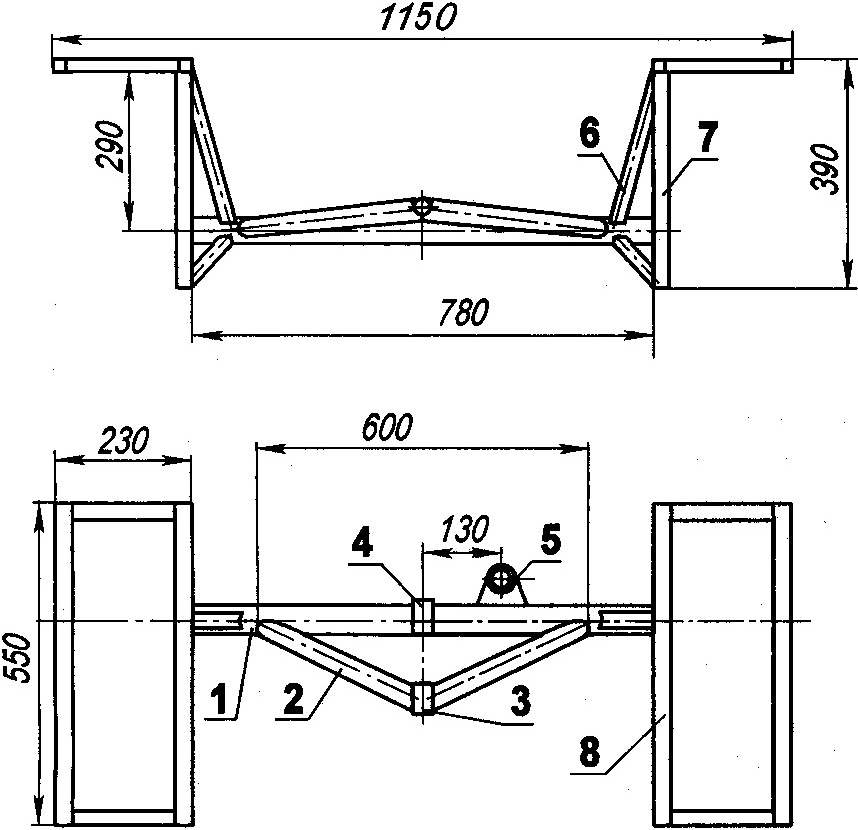
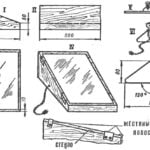
Blade (material detail, except for stressed — steel):
1—scraper (the strip of rubber s10); 2—shield (AMC s3,5); 3—front (tube 25×25, 4 pieces); 4—brace stand (tube 25×25, 2); 5—additional cross member (tube 50x25x2, L = 1210); 6 — main cross-member (area 45x45x3, L = 1210); 7—suspended stop (tube 50x25x2, 2); 8—suspension bushing blade (steel 30×8, 2); 9—brace for more cross member (tube 25×1, 2); 10—movable cross-beam end stops (trumpet 30x25x1,5,2); 11 —eyelet cable.
As the power unit chassis used the engine from a motorcycle “IZH-Planeta-3” capacity 18 HP Its cylinder was equipped with a homemade device forced air cooling with 8-blade fan in the casing. The rotation of the fan is driven by an elongated crankshaft of the engine through a V-belt drive (washing machine). The engine is placed under the seat, and attached to the frame using special welded brackets to using screws to move it to tension the chains of transmission.
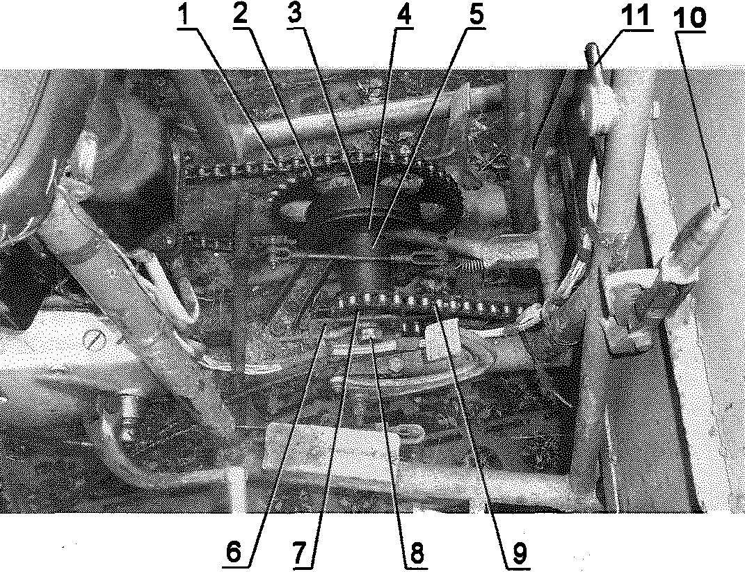
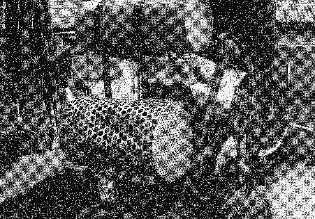
Intermediate gearbox, two-stage chain transmission:
1—circuit of the first stage (t = 19,05); 2—big star (Z = 53, combine); 3 —brake drum (motorized FDD); 4—the brake shield and pad; 5—bearing housing (from the combine); 6—tensioner; 7—small sprocket (Z = 15, from a motorcycle “IZH”); 8—intermediate shaft; 9—circuit of the second stage (t = 19,05); in this photo are clearly visible lever locking body (POS. 10) and the rear lever throttle (POS. 11).
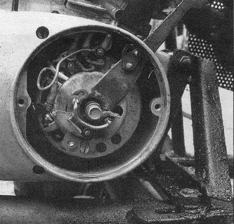
Drive the front wheels:
1—cut splined coupling (2 PCs); 2, 4—Hooke”s joints (4 PCs); 3 — segment spline shaft (2 PCs); 5 — drive sprocket of the main gear — counter shaft sprocket of the second stage chain transmission (Z = 21); 6—circuit second stage chain transmission (t = 19,05); 7—main gear — reverse gear; 8—wheel hub (tractor DT-75, 2 PCs.); 9—driving wheel.
Have the engine modified a standard ignition system. Instead of “odnolistovoe” coil set “doohickery” motorcycle K-750 and, accordingly, the second candle on the cylinder head.
Operation showed that the decompressor now the engine is not needed, it is sufficient to monitor the cleanliness and serviceability of fuel system and carburetor. Engine failures due to the lack of spark in the ignition spark is almost gone, what used to be commonplace. Changed the mount Board breaker — she is now seated on the alternator shaft with a sliding fit and can be rotated a certain angle, thereby adjusting the ignition. Board breaker is attached to the stator of the generator with the elongated screws, after which fixed with brackets soldered to them from wire.
Owners of single cylinder “IgA” familiar reverse strokes of the lever kickstarter, which sometimes leads to serious injury. This alteration completely eliminates this unpleasant phenomenon. Before starting the engine Board by means of a lever, derived through the casing of the generator, translated to “later” ignition and once the engine returns to its place. On the lever, in place of him from the cover of the generator, there is a lock box that its lug enters the groove on the lid, thereby providing a stable position of the lever Board to the desired angle plugs. To fine-tune the point gap of contact breaker box is made movable. According to this principle, converted all single-cylinder engines”, IIA”, I applied.
The muffler used from a snowmobile “Buran”, it is compact and quite effective. To regular input ports of the muffler are welded trimming exhaust pipes with collar nuts from the “IZH-PZ”.
Since the engine is located at the rear of the frame chassis and drive wheels — front, the transmission of torque from the power unit to the main transmission had to be through a two-stage chain transmission from the intermediate gear. Circuit has broadened, combine. From the combine, and a large (Z = 53 tooth) sprocket on one end of the intermediate shaft. On the other end of the shaft mounted sprocket Z = 15 from the rear wheel of a motorcycle “IZH”. In addition, the intermediate shaft is mounted the brake drum (welded to the motor sprocket) from wheel motor scooter “Vyatka”.
Homemade cover brakes and pads — regular motorolleri. The shield is attached to the frame using two brackets in the form of paws. This provides for the possibility of orientation (a small move and rotate) shield with pads relative to the drum. Intermediate gearbox itself can also be moved along the side members of the frame for tensioning the chain going to the main transmission.
Main gear (or reverse gear) used from motor scooter cargo “the Ant”. It is subjected to modernisation: instead of the standard narrow differential gears and reverse gear is installed, extended from the wheelchair to the FDD. Of course, if you strictly follow every time for weight and don’t abuse tractive effort of the power unit (and who, incidentally, capable of large loads), then these alterations reverse gear is not required. The drive sprocket of the main gear (aka sprocket driven second stage chain transmission) is also taken from the wheelchair.
In principle, the reverse gear can be used from strollers FDD. However, he idler gear reverse gear mounted on the shaft in the plain bearing (bronze bushing). With intensive use reverse’ (which is when the plots of the tractor is not such a rarity) so the bearing goes down, and it is better to replace bushing for a bearing.
Transmission of rotation from the main transmission to the drive wheels is via a few fairly intricate axes, each consisting of two full-time elastic universal joints with short splined shaft between them, welded to the second hinge (the middle to the wheel) cut spline clutch connected with the shaft of the hub. The last detail (slotted coupling, shaft and hub) is used from Puscuta tractor DT-75. By the end of the hub shaft is welded flange with studs for mounting the driving wheel.
Of course, the axle shaft is quite complicated, and if, for example, to produce an elongated hub, the second hinge and is not required. But I assumed that you had available.
The front wheels are used from the UAZ. But the tyres they have improved in the deep “chequered” for better traction plowing the roads and in slush. The tires are also much easier. I believe that these tires are very suitable for off-road equipment. The technology of their production are described in No. 9’2008 “Model construction”.
Rear axle chassis has the shape of an isosceles triangle, because to the beam (pipe 42×3 mm) welded two of the same strut from the pipe 32×2. 5 mm with sleeve at the vanishing point. Exactly the same sleeve and in the middle of the beam top. Through these bushings rear axle is suspended on the brackets of the frame with zaspirtovannyh pins. This suspension allows the rear (and front) wheel well copy the track profile, without twisting the frame, and prevents hang some of them above the pits.
On the ends of the beam rear axle are mounted the uprights of the channel, which are attached to the steering knuckles, and the top uprights are welded to the brackets from the corners for the device here rear fenders-fenders.
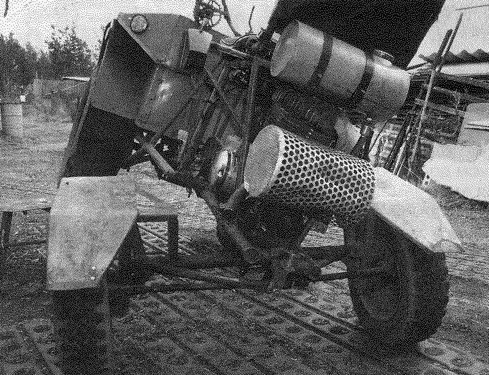
System of forced air cooling of the cylinder (casing removed).
Traction and the l-shaped lever steering.
a Lever changes the angle of the closed state of the contacts. You can clearly see the bracket of the engine mounts to the frame with tension screw.
controls motohashi:
1 —a coupling pedal; 2—switch ignition on; 3—winch for lifting-lowering of the body; 4—reverse lever; 5—rudder; 6—the switch of headlights and rear lights; 7—control lamp of the generator; 8—control lamp neutral; 9—the location of the shifters of the air corrector; 10—the lever of the locking body; 11—throttle; 12—the brake pedal.
The rear driven wheel and the steering knuckles (as, however, and the steering gear and tie rods) used motorized wheelchairs from the FDD. Of these nodes superfluous rated dismantled the brakes. Of course, the wheels of the wheelchair much less wazowski diameter, which reduces the permeability, but with them higher maneuverability, and is for the small machines is much more important.
To beam rear axle, to the right of the middle, welded the glass in which the bearings are mounted l-shaped lever, one end of which is driven by the longitudinal thrust of the rack of the steering mechanism and the other end moves the two tie rods of the respective wheels. Due to the large stroke of the beam when the tractor is on difficult sections of the road diameter of rear wheels cannot be increased without increasing the width of the rear axle because of the emphasis of the fenders in the engine in extreme positions.
Rear axle.
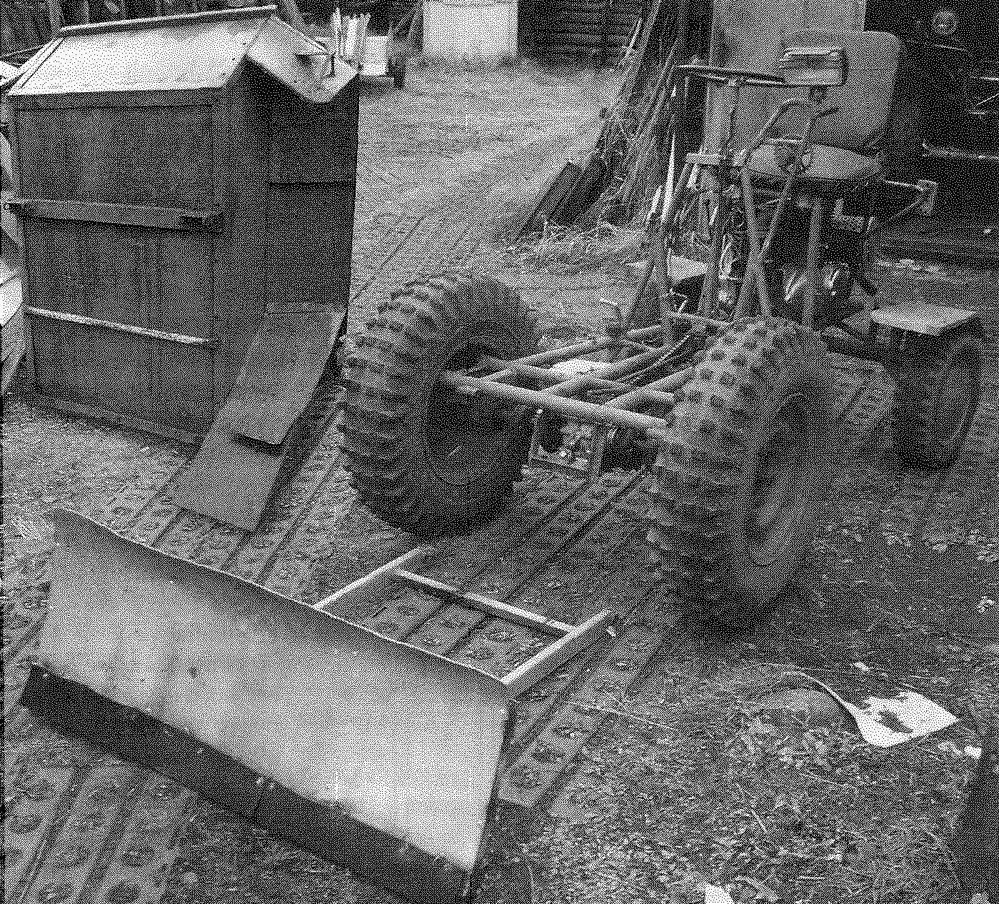
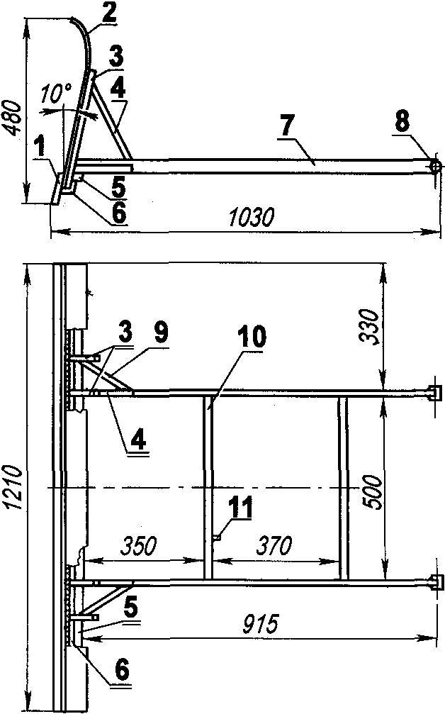
The body of the tractor — welded. The frame is made from a variety of angles and sheathed with a sheet steel 1.5 mm thick. All the angles on top of the body are rounded to avoid injury.
Approximately 1/3 of the length of the body from the front side from the bottom to the transverse part of the frame welded two sleeves, through which the through pins it is hooked to the eyelet welded to the first crossbar of the tractor. The wings of the front wheels is welded directly to the body, have multiple functions — extend the loading area, serve as protection against splashes and increase the stiffness of the body itself, as the tractor sometimes have to carry large weight loads.
For transportation of bulk materials most of the volume is placed on the front of the body, which makes it easy to tilt forward almost vertically, without tools. The inclined front wall and installed with a slope to the inside of the wings contribute to the unloading of materials, almost without a trace, especially if you give the tractor back.
Electrical equipment staff sectiontwo. Staff also the carb and air cleaner. Switch ignition on and simultaneously connect the battery. Here on the dashboard is a rocker switch on the headlights and the tail light. It is installed and the control lamp “neutral” and operate of the generator. Also improve the security and reflectors mounted on the body.
The controls include foot pedals: throttle, brake, and clutch. It should be noted that the throttle is spring-loaded additionally: it is necessary for more precise control of engine speed in terms of pollution and traffic on the road. On the dashboard in front of steering-wheel-mounted control lever to reverse. Two hard thrust and intermediate l-shaped lever mounted on the steering, switch into reverse gear. The lever on the reverse is spring loaded for better fixing it in the extreme positions in shaking conditions.
Hand winch for lifting and lowering the blade is a roller with a small drum with cheeks, preventing a descent of the rope. The roller rotates in a glass bearings, glass welded to the bracket farna. The control handle of the winch plate is pressed by a spring to the gear wheel that is welded to the glass-the hub of the roller, and serves to block the handle with a tooth entering into cavities of zubchatki (the gear — children’s bikes). The cable is wound on the winch drum via a roller mounted at the bottom edge of the body and through the same roller, located on the first crossbar of the tractor, pulls the crossbar of the blade. The blade is hooked to the frame of the tractor in two brackets-ears hanging racks. On the outboard ends of the blade are thrust bushing which are inserted in the eyelets of the brackets and are attached here by pins with splineway. The blade is simple, I just want to note that the increase in its mass is not desirable — it leads to increased effort on the handle of his recovery.
For this reason, the suspension stops with cross members forming the frame of the blade, made of thin-walled tubes with the exception of the lower area of the main cross-beams, and a shield made of duralumin. At the bottom of the blade are attached to a removable rubber band, they are release from the bottom 30 to 40 mm for cushioning on bumps. In the upper position of the blade is pressed against the body and not swinging when moving the tractor. Of course, if you set the blade body can not tip over, but in the winter the carriage of bulk cargoes is extremely rare, and if need to remove the dump in five minutes. For better traction when clearing snow in the back placed the ballast (20 — 30 bricks). You can also apply snow chains.
As mentioned, the driver’s seat leans back, opening up access to the spark plugs, tool box and bobbin, as well as facilitating the approach to the carb. There, inside the seat frame secured regular relay-regulator and terminal Board. Behind the seat on the plate bracket that is welded to the seat frame are secured using clamps fuel tank of 6 liters. Fuel feed is by gravity, using a standard tap.
Kickstarter Lever from “IZH-Jupiter”, it can be folded without interfering with the driver to include transmission elongated lever. The lever of a fuel corrector is mounted on a vertical tube steering rack, drive corrector to the throttle of the carburetor — budenovskiy cables. The clutch pedal associated thrust with an l-shaped lever, the lever, the other end pulls the rope cutoffs of coupling. Brakes are actuated by the pedal via two rods with the intermediate yoke. Both thrust are adjustable in length. To replace the brake pads cover can be moved along the pipe of the second rod.
In conclusion — about the features of the control gear. Do not abruptly slow down, which leads to peak loads in the transmission. “Spiked” summer tires have a high grip (especially at a loaded tractor), and the brake drum is easily blocked. It is dangerous to maneuver in reverse with great speed: if Zadneprovsky wheels disappears “steering feel”. Note that the back of the front noticeably faster, and hence less traction. On dry soils the unloaded tractor can dig on the climbs. In such cases it is necessary to move backwards or put in the back of the ballast.
The size and maneuverability of the tractor allows him to “squeeze” literally any “gap”, and discharging forward tipping and a further retreat is very comfortable on a personal farmstead, where, as usual, the whole area is used. Small body height from the ground level for convenient loading and unloading, while the low centre of gravity contributes to the stability of the tractor on the slope.
Mini-tractor is able to haul more and trailer with capacity up to 500 kg. Front and rear side of the trailer is hinged, so it can be used as a dissolution for transportation of long goods.
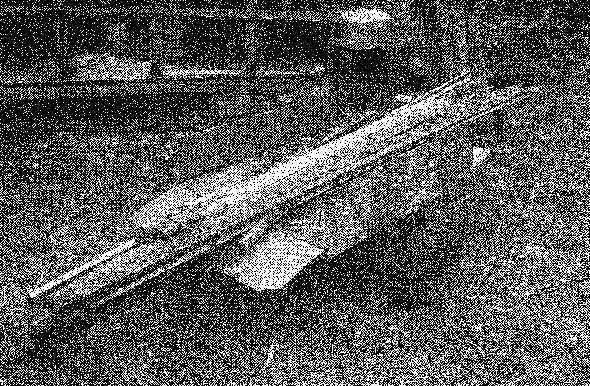
Trailer for mototaxi.
Tried to hang on the chassis of the plow and plow. It turned out good. But I for these purposes there is also Motorbade.
A. KOKSHAROV
Recommend to read
 CLEARANCE-MACHINE
The frame is made of planks 10 mm thick, glued with joiner's glue. The lazy side walls are inserted two ordinary glass and are secured with strips of sheet metal. A stand for the bulb to...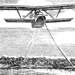 Hydroplanes BRO-16
Hydroplanes BRO-16 — single-seat biplane of wooden construction, designed for training and demonstration and training flights. This is the first machine of this type, established in the...
