
 To create a device is simple, inexpensive to perform and at the same time with high performance — such is the aim of gliders. We offer our readers the description is very promising glider “Albatros” open class, created by Moscow engineer A. Z. by rabanim in early 1978. This device has been widely tested and has a high aerodynamic qualities. From other phones open class “Albatross” stands simple design (all tube frame straight), in combination with precise profiling of the dome, which provides pre-curved armor combined type (front — hard, back — elastic). The frame of the Albatross allows you to apply domes of different shapes and size without any alterations and additional adjustments.
“Albatross” glider of the open class. The most characteristic features of its construction — profiled wing with a planar cutting polycrylic and aerodynamic twist of the wing. They give the machine good directional stability and the ability to demirovici gusts of wind. Pitch stability and preventing disruption of the air flow at the minimum speed provided by flexible S-shape at the trailing edge of the canopy and developed radial battesimi. To increase stability and reducibility of the glider to the wind contributes to the keel area of 0.4 m2. Big load on 1 m2 and the peculiar shape of the dome make the “Albatross” is very maneuverable with a relatively small load on the control stick.
Structurally, the above features are expressed as follows. Profiled wing is formed by nelokalnoe dock polacrilin, mating dome at the root of the chord (on the keel), profiled lats and coolnote of 0.5° (the angle of the dome 1° greater than the angle of the frame).
The allowance for the root of the chord is achieved by moving the rear part of the dome 60 mm forward on the keel, the height profile at the root of the chord is 8% for the fabric of AZT, and 7% for Dacron.
The front half of lats hard and form corresponds to the selected profile. A duralumin tube Ø 10 mm with a wall thickness of 1 mm. Flexible back part of the plastic guide pins for glass shelves. Her tails gently curved upwards to a height of 1% chord: beginning of the bend shall deviate from the tail at 15% of chord.
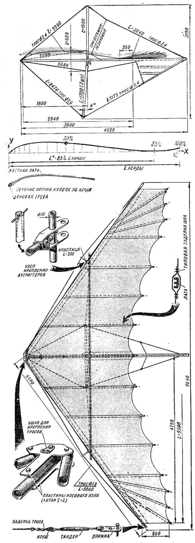
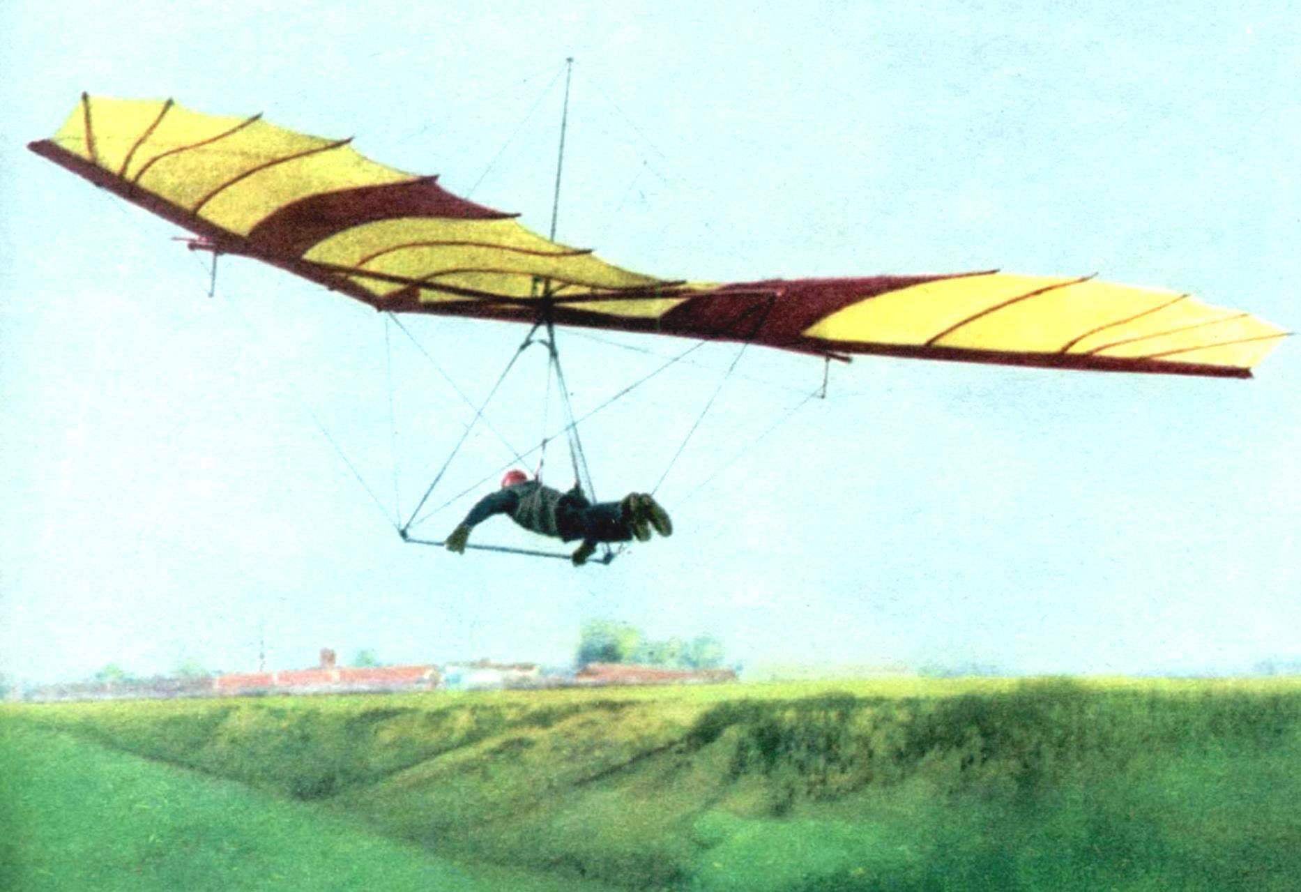
Fig. 1. General view of the hang glider “Albatros” at the top and side.
Battens pass through the dome to the tubes of the front edge and lean on them. Between the armor on the rear edge of the dome done by the cuts — 20 percent for fabric AZT (or 15% for Dacron). Due to this, the dome takes the form of a wrinkle-free and eliminates the danger of “zapalskiene”.
Aerodynamic twist suggests a linear increase of the profile height from 7% at the root latte to 14% at the outer radial battens.
Note that to obtain high performance it is necessary very precisely to withstand all of the parameters. For beginners we recommend to increase Qualinost to 0.9°.
THE DESIGN OF THE FRAME
The frame of the “Albatross” consists of two side and keel tube, cross member, steering linkage, mast, Central node, nasal node, edge outriggers, cables leading edges, upper and lower wires, a carbine with a clamp for the suspension of the pilot and the connecting spacers. Pipe — D16-T Ø 40X1. The length of the four parts of side pipes of 1500 mm. Keel — three lengths of 1500 mm. the Segments are joined by means of connecting spacers. The tail ends of the end plugs, and the closed nasal bougies of dense foam. Lateral pipe at the connection with the cross member is reinforced by a spacer (L = 190 mm). The last hammered by a bougie of a dense foam that performs the role of guide for the bolt in the edge node. Likewise, communication of the elements of the aft and fore parts, but spacers can be shorter.
Cross bar is made of pipe D16-T Ø40X1 and consists of five segments: two internal 1500 mm, two external and 1270 mm Central length of 74 mm. Inner and outer parts are joined also with the help of reducers. The ends of the transverse pipe end plugs. Where openings are provided for bolts of fastening of lateral pipes, spacers are used with foam. The Central section onto the mid pipe D16-T Ø 38Х1;5 and a length of 240 mm. that part where there is a bolt hole, a Central hub is filled with foam.
A steering linkage of three pipes D16-T Ø or 30Х1 26X2,5 with a length of 1700 mm. Their lower ends are joined dural cheeks. Each end is secured by two M5 bolts, and the ends of the side — one bolt M6. In addition, a M6 bolt is attached to the cheeks shackle for fixing the ends of the lower wires and a safety cable. The Assembly of the upper part of the trapezoid with the bracket Central node on the M6 bolts; the ends of the pipes clogged with foam.
To fold the trapezoid, it is enough to remove the bolt from the lower corners.
The mast is made of pipe D16-T Ø 26X2 (30X1,5) length of 1500 mm. the upper end of the end cap. Between it and the pipe end is mounted curly washer, which serves to attach the upper cable. The lower end of the mast is attached to the bracket with the bolt M6.
The Central node consists of brackets, the Central M10 bolt with castle nut and notched spacers.
Bow knot includes two plates and four bolts M8.
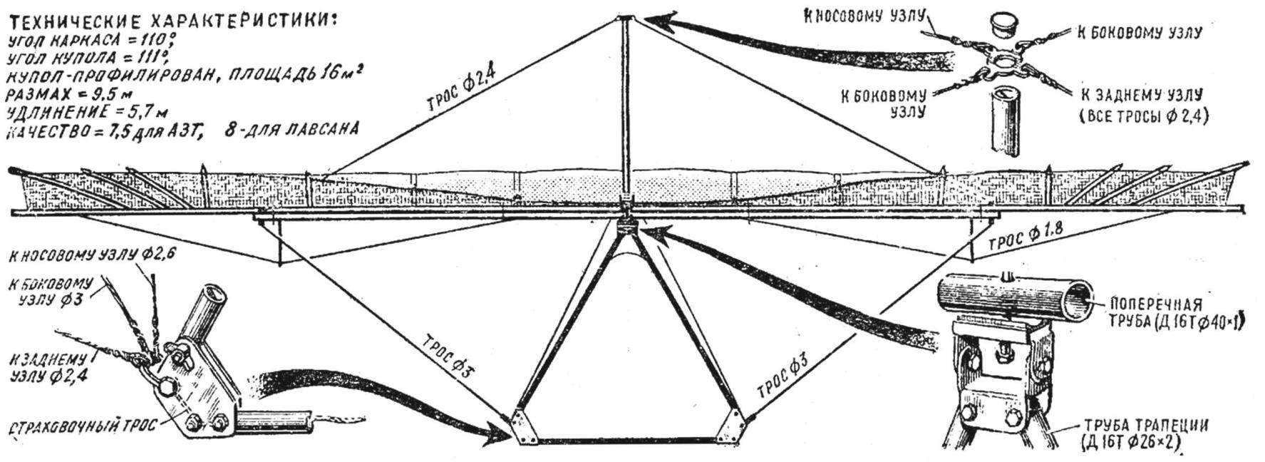
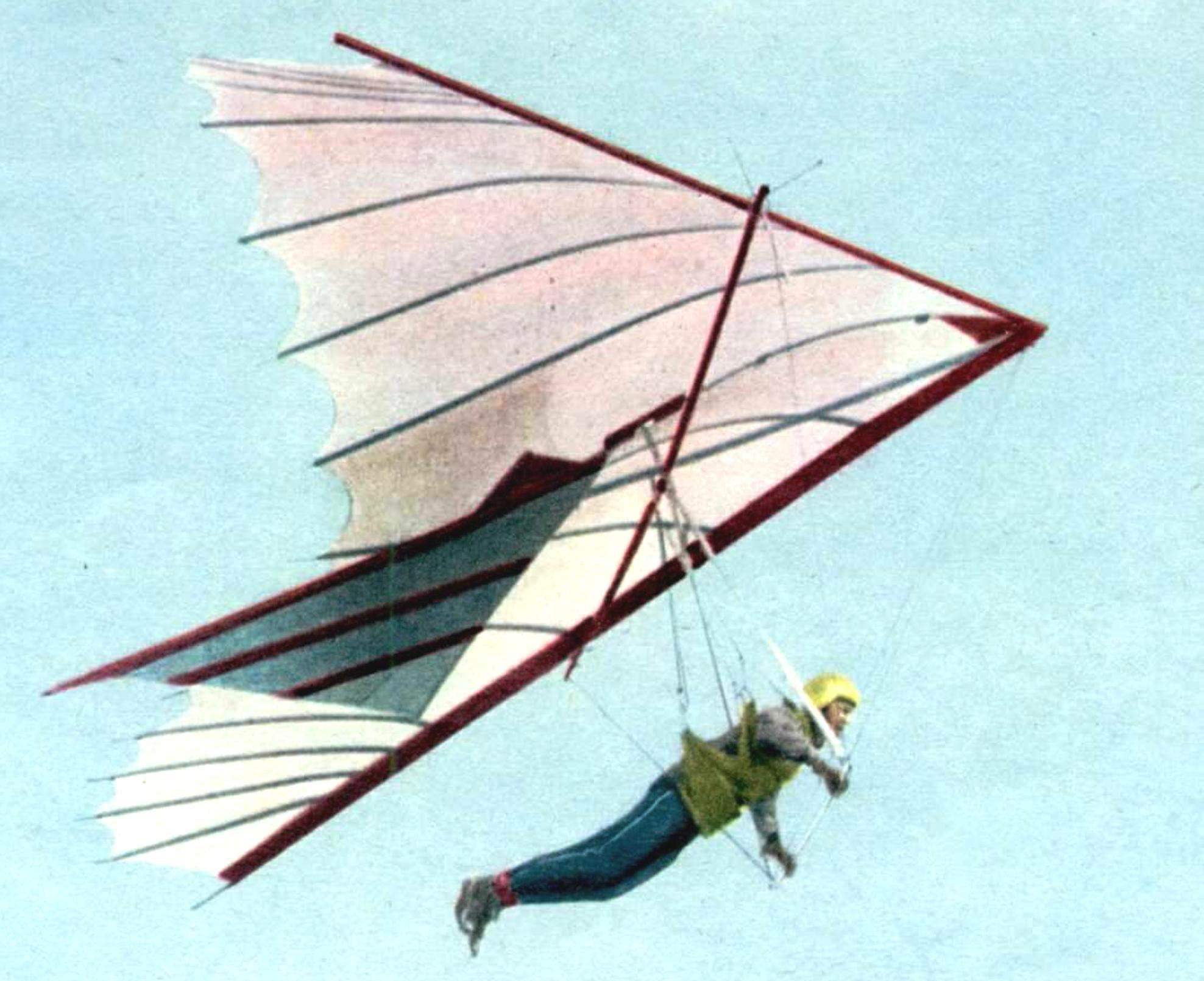
Fig. 2. View of hang glider “Albatros” at the back and design details
The edge nodes consist of the four notched washers and M8 bolts with wing nut.
A/the trigger is collected from fixed pins vertical and horizontal pipes, and bracket. The ends of the latter cover the side pipe through the notched washers and have a bolt hole in the edge node. The edge cables are based on the ends of the tubes outriggers and fixed with springs.
The front ends of ropes with buckles are attached to the nasal node on the extreme bolts. The tail ends over the same buckles with three holes, the spacing of which is reduced for more accurate adjustment. Buckle the upper and lower edge wires are attached together with buckles of the dome to the rear of the side pipe bolt M6.
Buckle side edge of the cable is fixed to a separate bolt MB. The selection of the openings of the buckles of the upper and lower wires of the tail end side of the pipe rises to 40-60 mm up to positive V-shape at the wing tips. This provides the necessary stability roll (especially at high angles of attack) and the parachuting mode. In this case it may be necessary to narrow down the 8th piece of the dome (for example, using tuck for the entire length of the 7th armor) to provide a more effective work of bettenson. The lower ends of the upper cables frame end buckles; the lower ends of the front (or rear) and the right (left) of the wires are installed the turnbuckles. The lower ends of the bottom wires of the frame are attached to the arc. The upper ends of the front and rear lower wires end buckles. Buckle the upper and lower front wires are attached to the front bolt of the nose node. Buckle lower rear and upper rear wires and keel box are attached to the keel bolt M6 with a wing nut. The upper ends of the lower lateral cables end buckles. Buckle side upper and lower wires are fixed to the ends of the cross pipe with the M6 bolts with wing nuts. The exact point of suspension of the pilot is carried out by movement of the clip with a carabiner along the keel tube. One end of the connecting spacers is fixed to the pipe with self-tapping screw or rivet.
THE TECHNOLOGY IS CUTTING AND FABRICATION OF THE DOME
With metal roulette construct a triangle ABJ (corner of the dome is taken greater than the angle of the frame by 1°). Between vertices A, B, W tighten nylon thick thread (lace). From the point W is the interval of 350 mm. On the perpendicular end of the line and measured the width of the fabric (0,8—0,88 m), which defines a point Through L. it is necessary to draw a line under an angle of 74° to continue straight ALREADY and also to pull the thread.
The cutting of the fabric is conducted sequentially, starting with the first piece of the left wing. The fabric is placed under a stretched thread, colored pencil is applied to the line of the upper bevel along the arc and line the bottom of the cut height of 20% of its chord. The bevel and the cut piece is cut, rotated around the perpendicular and superimposed on the fabric of the mirror. The contour lines are drawn the ends and cut off the same piece and the right wing.
The first piece back into place, and on its edge with an overlap of 50 mm superimposed tissue from which in a similar way are cut the second pieces, etc.
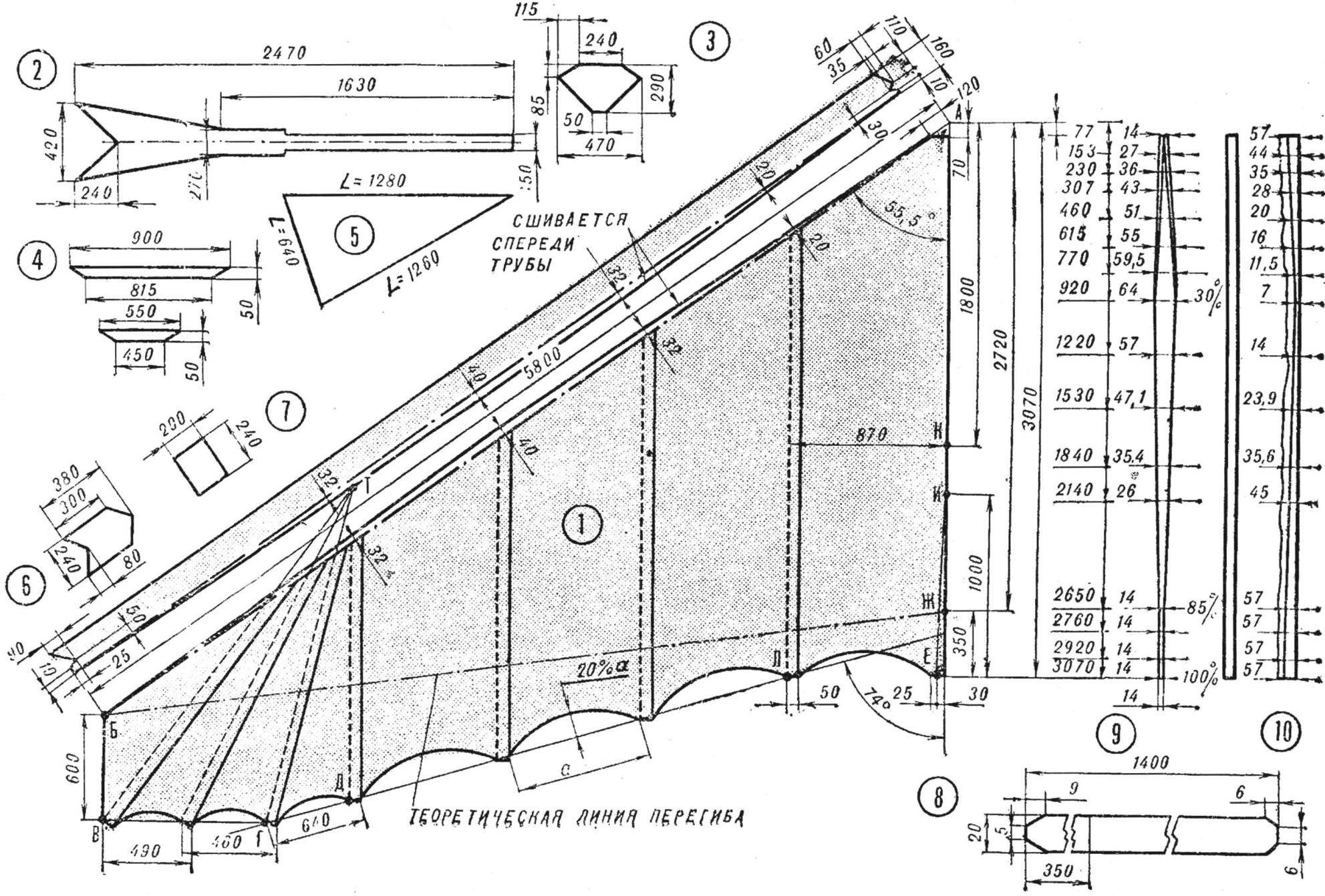
Fig. 3. The construction of the dome and its parts:
1 — wing (Assembly diagram), 2 — keel pocket, 3 — panel front corner of the dome, a 4 — patch lining for lackerman of Kiel, a 5 — circuit keel, 6 — trim the end of the keel pocket 7 — pad fixing bolt hole of the transverse pipe, 8 — pad on the dome is at the root of the chord, the 9 — patch wedge, 10 — option overlay polycrylic bases wedge
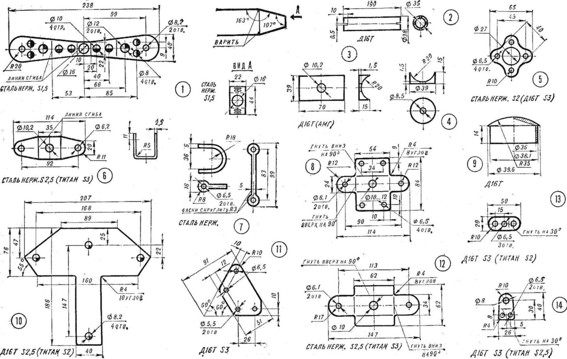
Fig. 4. The metal parts of the frame:
1 — mounting bracket outriggers: scan, weld, baffle, 2— spacer, for joining pipes, 3 — gasket, 4 — notched sealing plate, 5 — a crosspiece of the mast, 6 — mounting bracket of the mast, 7 — handle, 8 — bracket No. 1 Central node, 9 — plug pipe, 10 — plate hull front, 11 — cheek steering linkage, 12 — bracket n 2 to the Central node, 13 — buckle fastening wires of the side pipe 14 — eyelet cables to the bow node.
After cutting four pairs of pieces necessary to build a radial battens. For this,go from point B parallel to the line as MUCH to delay period BV = 600 mm. From point to hold In an inclined straight line so that it crossed the line BJ his middle. Then extend it to the intersection with the continuation of the line of the outer edge of the fourth piece (point T). From point T along the radii would have to follow the directions of the three radial bettenson. The radius of the radial outer TV lies, battens, To build an internal radial battens necessary from the point In to draw a line perpendicular to a line until the intersection with the line of 74° at point G. the radius of the TG will lie inner radial battens. To construct a line average battens necessary from the point T draw a straight line to the intersection of the line VG, so that the area of a sector of VTG was divided in half.
If due to the smaller width of the fabric material, the size of the chord ED is greater than the chord of the cut edge of the fourth piece, the point d must move on a line, DG to the difference of the lengths of these chords, again to repeat the construction of the inner and middle bettenson. Continue cutting 6 th — 8 th pieces according to the lines, and the warp threads of the fabric, Orient the bisectors of the sectors.
The choice of the area of the dome must match the specific load of 5.5—6 kg/m2, it is calculated according to the formula:
S = (weight of pilot, weight of machine, weight of clothes, the weight of the Shoe…) kg/ 5,5—6 kg/m2
To increase the area of the dome is recommended to increase the distance ALREADY, and the length BV of up to 680 mm and, if necessary, scale up to 10 m (maximum 11 m).
When S = 17 m2 — AK = 1820 mm;
S = 18 m2 — AK = 1870 mm.
To reduce the area is recommended to reduce the wingspan and right, but the BV should not be less than 500 mm (e.g., for S = 14m2 and AK = 1700 mm).
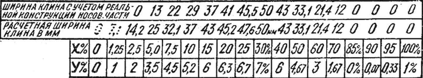
Fig. 5. Table of ordinates to produce an S-shaped profile of the dome.
All the details of the dome are connected by a seam zigzag of width 3.5 mm and a stitch length of 2 mm. Overlay piece to piece with an overlap of 50 mm forms the pockets for armor, If necessary, the amount of overlap can be changed. As an ultimate minimum, the overlap should be not less than 7 mm (for the two joints “zigzag”), but in this case, pockets for LVL can be cut out of cheaper and less durable material and sew the bottom of the dome. To strengthen the latter in areas of the front ends of the lat to the corners of the triangular pieces sewn lining. After that, all the pieces of the dome are sewn together. When ambrosia fitting stitched polycryl overlap each other to check for symmetry and, if necessary, otkrivaetsa to each other around the perimeter and at the specified corner of the dome (it has to be 1° greater than the angle of the frame). After that, edge pockets with arcuate edge sutured to the dome, for this they place on top with an overlap of 10 mm.
Both wing are connected through a wedge with an overlap of 7 mm — two stitches on each side. Polycryl you can also splice, but this took into account the shape of the wedge.
Plate for strengthening of the dome at the junction of the side (edge) and the transverse pipes and attaching the dome to the end of the side tubes sewn from the bottom; it is better to carve out a more durable fabric.
When the second fitting is necessary with a pencil to strike on the dome of the line along which to sew the second edge of the edge of the pocket. The material of the pocket fold to the seam line and is placed under the dome in this case draw a line along the edge of the pocket. The last place along the marked lines evenly on all length and to facilitate the stitching process make marks with a pencil on the pocket and the dome every 200-300 mm.
For adjusting the tension of the pocket on the side (edge) the tube buckles have four bolt holes.
The upper part of the nose end of the dome is strengthened with Mylar tape, and the ends thereof are joined together at the bottom and not sewn to the edge of the pocket. Ribbon ring covers the nose of the frame and is designed to hold dome. The rear edge of the dome is strengthened with a tape width of 14 mm, made of a fabric dome, which is formed along a common thread and smoothed in the middle.
For attaching armor dome to the ends of the pockets at the trailing edge sew the loop (two for the lat), it attached to the ends of the laces, attracting the dome to the ends of the lat.
Latu at the root of the chord in front and behind of the mast and the first and second battens on each wing, it is advisable to pull up to the top wires of the frame to counteract the dive. To do this in the appropriate places lat pockets sewn Mylar hinges.
Keel pocket is made of double layered and the front part is attached to the dome so that the distance between the seams equal to the diameter of the pipe. The tail part of the pocket forms a stocking at the end of which is sewn Mylar tape with a buckle under the mounting bolt to the keel. The ribbon is sewn from the dome to the rear end of the grip.
Keel with two pockets for wooden lat ciliosa is sewn to the pocket bottom. The leading edge (L = 1290 mm) stitched the pocket to the dural tube Ø 10X1 mm bottom end fastened with ropes to the rear bottom wires of the frame. The trailing edge of the keel is reinforced Mylar tape.
For the final test of the dome on the symmetry and the magnitude of Qualinesti of 0.5° is necessary to collect the device. Then the glider is inverted with the mast down, stretched the thread between the point of attachment of the dome on the end of the side (edge) of the pipe and the tail root of the chord and measure the distance between the filament and a dome in the place of greatest sagging. It should be 300-340 mm, and the difference in the distance from polacrilin not more than 6%. Beginners learn to fly, it is recommended to increase the stability of the apparatus. For this Qualinost should be increased to 500-600 mm, reducing the angle of the frame to Qualinesti of 0.9°.
More hard edges, made of pipe 40X1,5 or 42X1,5 (45Х15), allow you to fly without outriggers of cables. But in this case, the front part of the dome need to cut the arc with a height of 110 mm (80 mm) instead of 40 mm shown in the drawing.
A. RYABTSEV, engineer
Recommend to read
 THE TRACTOR BEHIND THE TRACTOR
The journal "modelist-Konstruktor" Simonov from the village of Saratov region. Podsosenki started reading twenty years ago. Holds a binder and writes it still. Loves to make homemade... CONCRETE PATTERNS ON THE TRACKS
Beautiful and elegant look of Park paths, lined with small plates. Why not adopt a similar method of covering tracks in the garden area? Because concrete is more durable and clearly...
