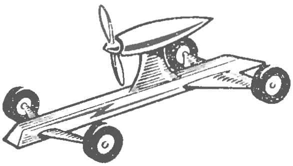
 At this stage of the work, outline the design of the actuator, which provides translational movement of the model. Let’s start with the analysis of the already known mechanisms, which are used in a large technique (Fig. 1). Under the terms of our problem, the most acceptable is the idea of using the wheel.
The next step is the move from General ideas to specific wheel design for each of the considered cases.
The design of the wheels must first ensure the patency of the device along a predetermined surface resistance when moving at a given speed, the reliability of the entire device, a sufficient strength with minimal weight.
In addition to basic, functional requirements can be called for more to improve the quality of the wheel manufacturing (precision, surface finish, strength, etc.). Permeability will be considered satisfactory if, when tested, the model will be able to move at a given speed on a surface with a roughness no greater than 0.5 cm Such irregularities at first glance have little impact on the speed of the model.
In fact, everything looks different.
Let’s consider an example. If the bumps on the ground will be 0.5 cm, then in relation to wheel diameter 5 cm this amounts to a ratio of 1:10. If you increase the wheel diameter of the model to the diameter of the wheels of the car, go there 10-15 times, and at the same time to increase the height of the road humps, it is clear that the test models will be held at the site, as if strewn with big stones.
Take the wheel diameter for model (DC) is equal to 5 cm.
To achieve the necessary stability of the model in 1-m and 2-m options must be not less than three wheels. In the 3rd embodiment, it is necessary to ensure maximum stability of the device, that is, to put at least four wheels. However, if it fails one of them, the stability condition is violated, replace the wheels on the lunar Rover are virtually eliminated. To provide a construction for a solid, preferably each of the wheels to duplicate, that is, to put not 4, but 8 wheels.

The permeability of the model is ensured by choosing the value of the wheel diameter (DC) and the area of its support on the ground (OK). Bearing area of the wheel is easily determined by the formula:
OK = G/Pr·Zk cm2 , where the WP — allowed specific ground pressure (determined empirically), Zk — number of wheels on the model, G is the weight of the model.
Knowing the wheel diameter, you can determine the number of revolutions per unit of time (PC) required to obtain a given rate of motion of the model:
nk = V/MPC(R/C).
To obtain quantitative values of calculations and the results issued in the form of a table:

V1=3,14·5·10=157 cm/s
V2=3,14·5·18 = 283 cm/s
V3 = 3,14·5·0,1·1,57 cm/s
Corresponding to the original and calculated data at the speed of designed devices can be represented by a table:

Comparison of the results shows that the deviation of calculated data from the source do not exceed the previously adopted 10% error and can be neglected.
Now is the time to define technical requirements to the working surface of the wheels for the considered models.
The working surface of the wheels needs to ensure the continued secure engagement with the ground or with the floor, not to destroy them, to be strong enough and not create a lot of noise when driving.
Analyze known in the art solution (Fig. 2). A large part of the wheels used in motor vehicles (other than railway), has a rubber covering. We have set the wheel sizes for models in the first two options allow you to use ready-made wheels from a set of “Designer”.
To the working surface of the wheels of the lunar Rover rubber coating is not necessary: when large temperature fluctuations the rubber is aging rapidly, at low temperatures it becomes brittle and disintegrates.
In this regard, the working surface of the wheels of the lunar Rover while doing metal. That decision was taken in the design of the wheels of the Soviet lunar Rover. The basis of wheel design we consider here the model of the lunar Rover (3rd option) let’s take the idea of the wheel of lunar Rover, we will continue to fulfill it entirely of metal, stacked, with a ribbed working surface. To compile a working draft of this wheel you can also use the wheels of the Rover. The choice of metal will be done when updating its weights of wheels (when you build all units and mechanisms of the model). Detailing the wheels will be made prior to the preparation of the routing of its production.

So at this stage we defined the overall dimensions and the design of the wheel with respect to the working conditions of models in each variant; the speed of rotation of the wheels for the 1st option — 10 Rev/s 2 18 R/C and for the 3rd — 0.1/s; the approximate number of wheels FOR 1 “St and 2-nd versions — at least three and for the 3rd eight.
Offer to continue the solution we proposed earlier task (“modelist-Konstruktor” No. 9, 1974), to determine the design of the Executive device for the transport of trolleys that you can use:
a) in the machine shop, vocational school, College, University, industrial production;
b) on the economic yard, on the farm and other objects of agricultural production;
C) on the surface of the planet Venus.
LITERATURE:
Artobolevsky I. I., Mechanisms in modern technology. T. II. M., “Nauka”, 1970.
Ostrovtsev A. N., Bases of design of cars. M., “Engineering”, 1968.
Hansen F., fundamentals of General construction methods. L., “Engineering”, 1969.
Yavorsky B. M., Detlaf E. M., Handbook of physics (for engineers). M., “Nauka”, 1968.


