The mast is the foundation of the rig of any sailing tourist or sports craft, its most important unit. Its design and position determine sail area, configuration and aerodynamics, the ability to adjust sail thrust, and the design of the centerboard and the “ship” as a whole.
When building a small sailboat, you have to reconcile quite contradictory requirements: strength and reliability of parts with their minimum weight. First of all, the home builder should decide on the mast type and materials, choose a construction variant (including the mainsail attachment method), and select a suitable mast step design. Let us split this three-part task into components and consider them separately.
Choosing the mast type
The limited hull strength of a small sailboat forces you to increase mast strength. The desire to keep weight to a minimum narrows the range of suitable materials. Wooden masts are too heavy, warp and rot from moisture, are difficult to make, and good timber is hard to obtain. The same, except for fear of water, can be said about homemade fiberglass masts. Therefore, the most suitable material for us is thin-walled duralumin tubing. Especially after mastering two operations: assembling an external luff groove and turning the mast into a truss, which significantly improves the “strength/weight” ratio.
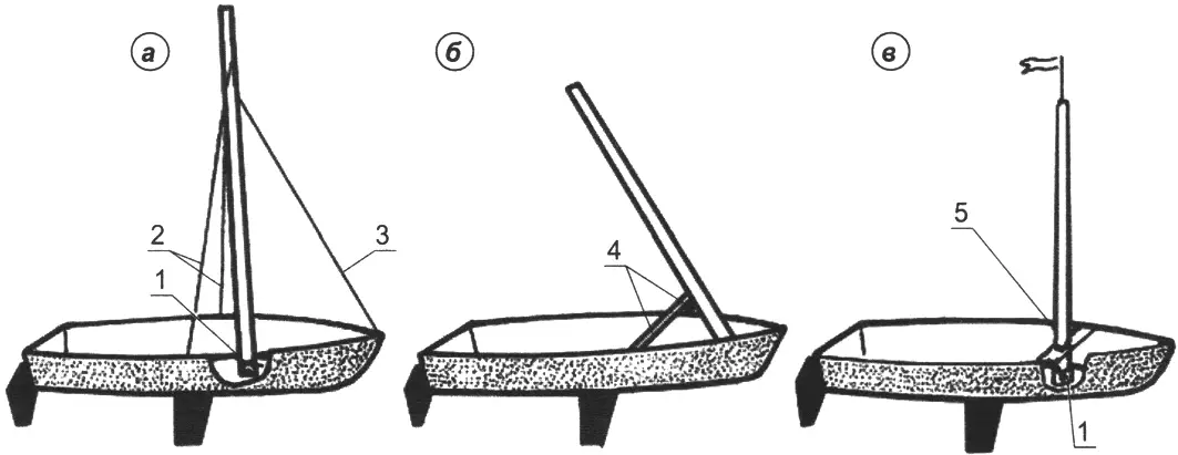
a — braced with stays; b — braced with struts; c — free-standing; 1 — mast step; 2 — shrouds; 3 — forestay; 4 — side struts; 5 — partner
On a boat, the mast is installed either with side and bow stays — shrouds and a forestay (Fig. 1a), or with side struts (Fig. 1b), or as a free-standing mast (Fig. 1c) and fixed at two points. The lower point (mast step) location does not depend on mast type. But there are options for the upper point. For a free-standing mast, it is the partner — an opening in the crossbeam. For a stayed mast, it is the points where struts or shrouds with the stay are fixed above the partner. Shrouds noticeably reduce loads on the mast and hull, but complicate their design. The angle between each shroud and the vertical must be at least 11°.
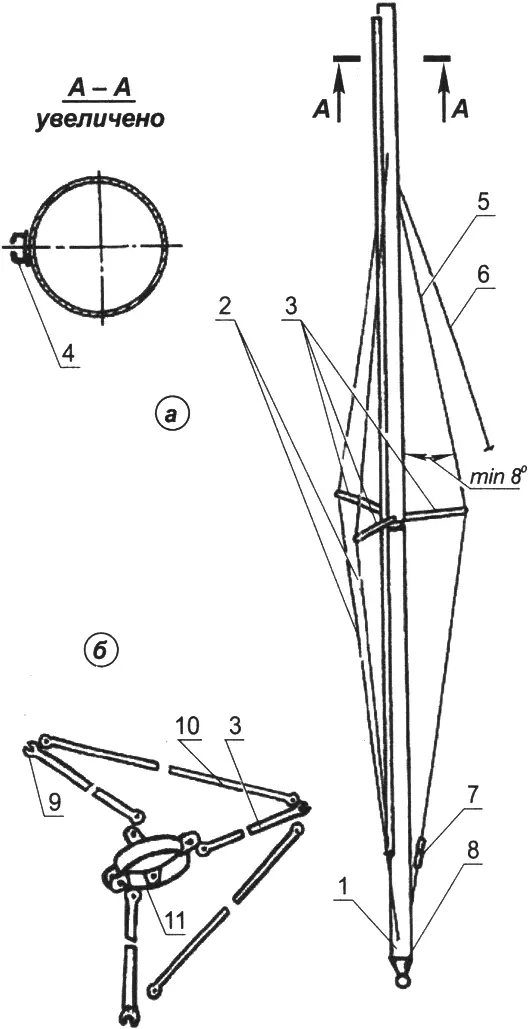
a — general view; b — spreader-node option; 1 — mast; 2 — aft diamond stays; 3 — spreaders (D16T, Ø12×1 mm); 4 — luff groove; 5 — forward diamond stay; 6 — forestay;
7 — screw turnbuckle; 8 — heel; 9 — slot for diamond stay; 10 — rod (D16T, Ø12×1); 11 — clamp (Kh18N10T s1.5-2 mm)
You can turn ordinary masts into truss masts (Fig. 2) using three stays made of Ø2-3 mm steel cable (diamond stays) and transverse spreaders. Truss stiffness increases if two rows of spreaders are installed. The angle between diamond stays and the mast must be at least 8°. Diamond stays let you adjust mast bend, thus changing mainsail profile and, as a result, thrust. This is done with a screw turnbuckle attached to the diamond stay, changing its length as it rotates.
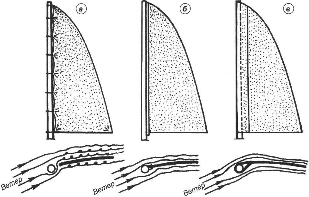
a — by rings (hanks); b — by luff groove; c — by sleeve on the mainsail luff
The external luff groove is assembled from a thin-walled U-shaped aluminum profile used in construction to hold window glass. It is shaped with a hammer and formers (Fig. 4), or by drawing between two grooved rollers of the required profile. Finished sections of processed profile are fastened to the mast with screws or self-tapping screws 3-4 mm in diameter. Holes for screws are drilled before profile deformation begins — this is important.
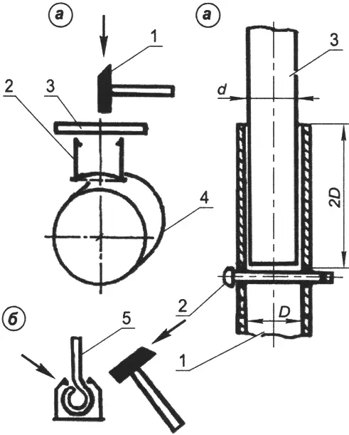
a — forming the cylindrical profile bottom; b — bending profile flanges; 1 — hammer; 2 — luff-groove profile; 3 — flat former (wood or textolite); 4 — cylindrical former (metal); 5 — shaped former (half of a window hinge)
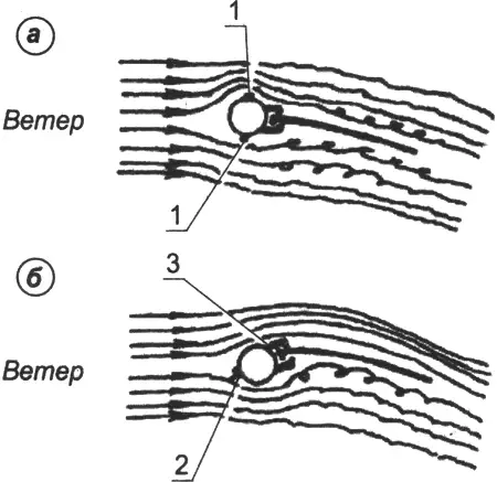
Mainsail thrust depends on how it is connected to the mast. Since a small craft also has a small sail area while hull and crew drag is relatively high, this unfavorable ratio significantly worsens windward performance. Two principles are important here. First, avoid gaps between mast and mainsail, because air leaking through them from the windward side greatly reduces thrust. This happens if the mainsail is attached with rings (Fig. 3a), hank loops, lacing, or sliders moving along a rail fixed to the mast. There will be no “holes” if the mainsail is attached in a luff groove — a longitudinal slot on the aft side of the mast (Fig. 3b). Second, avoid a step between mast and mainsail, since disrupted smoothness of the sail profile, especially near its leading part, also noticeably reduces thrust. A teardrop-section mast improves profile smoothness. Such a mast is very hard to make, but the mast can be made rotating, then the step between it and the mainsail is smaller. And if you use a sleeve, the sail profile becomes fully smooth (Fig. 3c).
a — non-rotating mast; b — rotating mast; 1,2 — shroud attachment points; 3 — luff groove
Of course, the easiest way is to make a free-standing mast rotate. But what about a stayed mast? At first glance, the forestay and shrouds interfere. But if shroud attachment is moved to one point (Fig. 5b), the mast can rotate left-right by 15-20°, which is quite enough.
Unfortunately, a mast with side struts cannot be made rotating. And this is not its only drawback, so this mast type is used rarely. Sleeve attachment of the mainsail is also not simple, because it creates a whole set of problems. It is known that a mast resists loads better, including those from the jib, if shrouds and forestay are attached not at the masthead but lower, at a distance equal to 0.12-0.25 of mast length. The forestay should be placed below the shrouds, or at least at the same level. A mainsail sleeve forces shrouds and forestay to be attached only at the masthead and to use only a masthead jib, which loads the mast the most. The same sleeve also prevents fitting diamond stays, so mast strength and stiffness must be increased significantly, and therefore weight as well.
Choosing mast construction
The way mast sections are joined depends on mainsail attachment method (Fig. 6). Variant “a” is universal; “b” is for a free-standing mast; “c” is for a stayed mast with luff groove. Luff-groove sections must align correctly, so adjacent mast sections during assembly must be fixed in a strictly defined position. The simplest way is using a screw head or rivet entering a slot at the lower end of the upper section (Fig. 6, item 6).
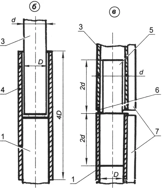
a — telescopic (D – d = 0.2…0.5 mm); b — on external sleeve (D – d = 0.15…0.2 mm); c — on internal sleeve with luff groove (D – d = 0.2…0.3 mm); 1 — lower section; 2 — removable support pin (rivet); 3 — upper section; 4 — external sleeve; 5 — internal sleeve; 6 — lock (rivet); 7 — luff-groove sections
Mast strength is also affected by boom attachment method. A thin-walled mast does not like being “perforated.” In this case, it is better to attach the boom to the mast with a surrounding clamp, which is easy to fix at the desired height (Fig. 7).
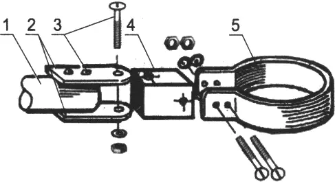
1 — boom heel, 2 — lugs, 3 — fastening screws, 4 — hinge “crosspiece”, 5 — mast clamp
The mainsail foot can be attached to the boom either by luff groove or by sleeve with a cutout for the boom vang pass-through. The vang is needed for Bermuda, gaff (including guari), sprit, and sometimes lug mainsails (if the foot is attached to the boom, not the yard).
It is best to tension the forestay, shrouds, and boom vang with a soft tackle — a nylon line Ø3.5-5 mm, reeved several times between two rings. For sail area above 10 m2, screw turnbuckles may be used.
Choosing mast-step design
If the mast must not rotate, as with lug and lateen mainsails, holes in mast steps are made rectangular or square (Fig. 8a). Mast heels can fit either tightly or with a clearance of 3-5 mm per side. Mast steps mounted on transverse or longitudinal beams of inflatable boats, rafts, catamarans, or trimarans allow laying the mast horizontally in any direction when needed (Fig. 8c).
Technical “details”
For masts, tubes of alloys D16 or D16T Ø35-70 mm with wall thickness 1.5-2 mm are usually used, less often 2.5 mm.
With mainsail area under 4.5 m2, diamond stays are not worthwhile: slight weight savings do not justify labor, materials, and time for assembly/disassembly.
The mainsail is attached with a sleeve primarily in a “cat” rig (mast plus mainsail) with a free-standing mast; up to 4 m2 sail area this gives maximum effect. It also makes sense to use a sleeve on mainsails in rigs with short masts: gaff, sprit, lateen, and lug. Here pros clearly outweigh cons: a masthead jib, although having maximum possible area, does not overload the hull too much. The mast in this case is most often free-standing, since weight difference from a stayed mast is relatively small. It is easy to remove and step, and to put the mainsail on it.
A free-standing mast is also often used in an intermediate variant, when the main sail plan — a “cat” rig — is supplemented in light wind by a light jib (that is, converted to a “sloop” rig). In this case the jib does not create high loads, and the mast remains relatively light.
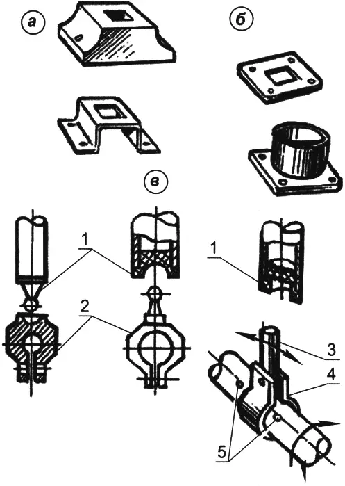
a — wooden and metal (shaped and tubular), for wooden rowboats and veneer boats; b — flat metal, for mounting on a kayak keelson; c — complex, for mounting on a multihull beam; 1 — mast heels; 2 — clamp steps; 3 — pivot pin; 4 — pivot clamp; 5 — limit screws
Standing rigging (shrouds, forestay, diamond stays) is best made of steel — it does not stretch, is thin, and therefore has low parasitic windage. Usually these are galvanized or stainless steel cables Ø2-3 mm, or wire Ø2-2.5 mm. Wire is stronger but may fail suddenly (usually near the eye at the end of the stay). Cable, however, “warns” of failure: its individual wires break first.
Running rigging — halyards, sheets, tacks, and vangs — is made from natural or synthetic ropes. Halyards are usually made from braided cord, because laid rope stretches under load and sails sag, losing shape. Halyard diameter is 6 to 10 mm. Sheets are Ø8-12 mm. Good jib sheets can be made from polypropylene rope, which is noticeably lighter than others.
The sail area of a monohull can be estimated by the formula: Smax= kLB, where Smax is allowable sail area; k is stability coefficient (for kayaks 0.6…0.7, for inflatables 0.7…1, for rowboats 1…1.2); L and B are waterline length and beam.
Depending on vessel specifics, this result may be adjusted. But increasing sail area too much is unsafe. It is better to split it into main and additional sails and expand the sail “wardrobe”: use main sails in moderate wind, additional sails in light wind, and storm sails in fresh weather.
Sometimes a jib is used instead of a storm mainsail if its area is suitable and strength is sufficient. As additional sails, larger-area jibs made from lighter cloth than the main sails are used first of all. With main sail area up to 6 m2, sail inventory can be expanded by using jibs made from regular polyethylene film.
“Modelist-Konstruktor” No. 6’2025, Yuri KUZHEL
Recommend to read
 STORM CARRIERS
the Main opponents of the American "new order" at sea the fleet of the Soviet Union, naturally could not stay away from the "missile mode". Especially as its had a good "platform": just... CAR FOR THE CITY
It is not easy to surprise residents of the city of Tolyatti with a new car. On their streets they are the first to meet promising models from the Volzhsky Automobile Plant and new...
