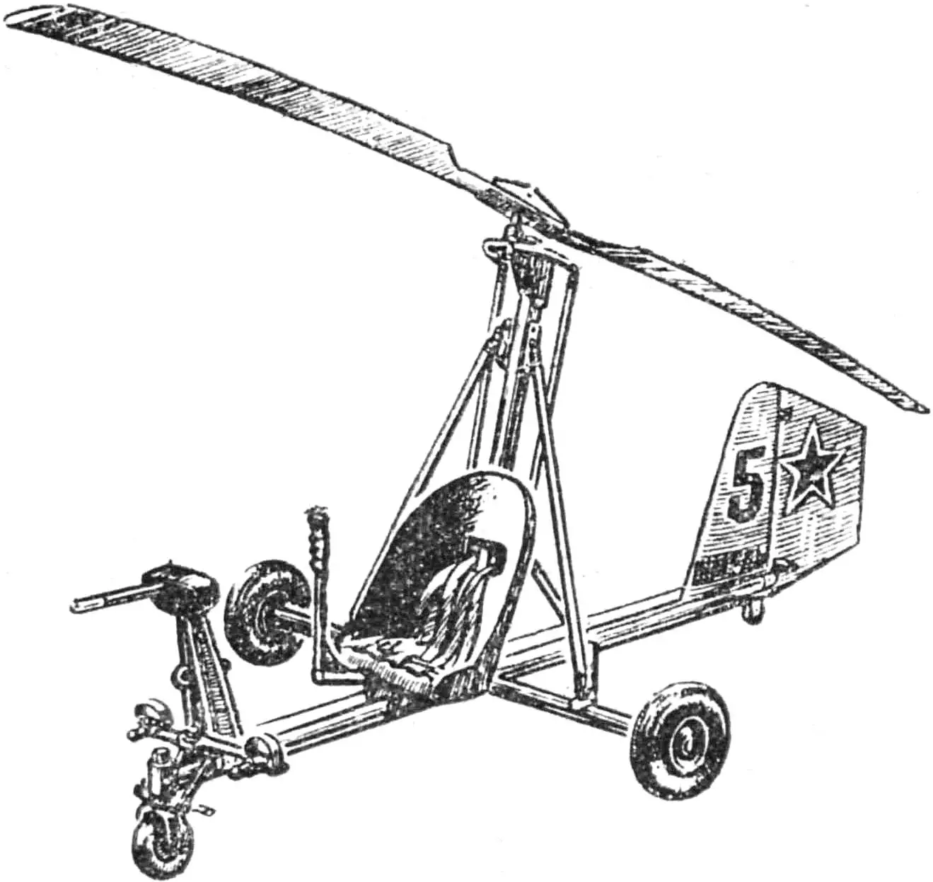
When designing and building the “Shmel,” the creative team “Vzlet” took as a basis the micro autogyro designed by V. Barkovsky, V. Vinitsky, and Yu. Rysyuk, described in detail in “M-K” (see: 1969, No. 6; 1970, Nos. 3 and 10; and 1971, No. 6). This very well-made machine, the first in our country of its class to fly stably, was exhibited at the central NTTM-74 show and was awarded a silver VDNKh medal. The basic layout, main dimensions, and manufacturing technology for the autogyro’s key parts differ little from what was recommended in those articles, so we will limit ourselves to the “Shmel” drawing in three views and focus on the changes introduced while refining the aircraft and flight-testing it. Let us say at once: we were able to use a number of ready-made units and parts from decommissioned airplanes and helicopters, which on the one hand somewhat changed the look of our machine, and on the other made the work much easier: many labor-intensive steps were avoided, aviation standard parts and good fasteners were used, and so on.
The structure is based on a flat frame welded from steel tubes Ø 50 mm. Its weight without equipment is about 14 kg. On the front of the frame is a truss made of D16-T angle 30×30, to which are attached a glider-type tow release, the instrument panel, and the pitot (airspeed probe) mast made from a duralumin tube Ø 22 mm. The pilot’s seat and harness set are from a decommissioned helicopter. The fin and rudder are also assembled from surplus aircraft and glider parts. Rudder area matters a great deal in towed flight, especially in a crosswind, so it must not be reduced.
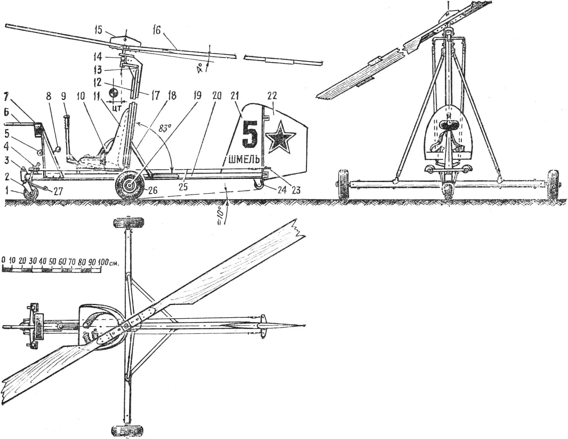
1 — steerable nosewheel (linked to the rudder pedals), 2 — wheel fork, 3 — fork kingpin, 4 — rudder pedals, 5 — tow-release hook, 6 — pitot/air-speed receiver, 7 — instrument cluster, 8 — tow-release lever, 9 — main-rotor control lever, 10 — harness straps, 11 — pilot’s seat, 12 — main-rotor control pushrods, 13 — hinge of the upper control yoke, 14 — main rotor shaft, 15 — rotor pylon structure, 16 — rotor blade, 17 — pylon, 18 — rear pylon brace, 19 — main-gear wheel axle, 20 — longitudinal base-frame tube, 21 — fin, 22 — rudder, 23 — rudder horn / balance fitting, 24 — tailwheel (hockey puck), 25 — rudder cable, 26 — main landing gear wheel, 27 — nosewheel brake plate.
The controls are entirely home-built, following the “airplane” layout described in “M-K” (1971, No. 6). That layout is significantly safer and more reliable in flight than the direct scheme recommended by Vensen. The control column shaft is made from steel tube 25×1 and 30×1. Control rods are duralumin tubes with Hooke (universal) joints embedded at the ends and threaded end fittings for adjustment. The rudder pedals are from a written-off Mak-15 glider; they are convenient because the pedal position can be adjusted for pilot height. The pedals are rigidly linked to the nosewheel, and the rudder runs on cables without supporting pulleys.
The rotor hub was made to “Modelist-Konstruktor” drawings with a small change: the bearing housing was machined from 30KhGSA steel rather than D16-T, because practice showed that a duralumin housing fails quickly.
The rotor blades are pine. The spar is delta wood, the metal nose cap is brass and is riveted through. Foam is used only to fill the rear part of the blade—from mid-span toward the tip. The blade is fully bonded with epoxy, shaped to contour and airfoil, then windows are cut and filled with foam. The surface is sanded, covered with 1 mm plywood, sanded again, covered with fabric, and painted. Tests showed that blades of this construction last much longer than those recommended by Yu. Rysyuk (“M-K”, 1970, No. 10), which crack after a few flights. The balance of our blades is within about 24% MAC.
The center of gravity of the assembled autogyro should lie within 40—80 mm ahead of the rotor axis (depending on pilot weight). If, when checking balance—which must be done very carefully before flights—a shift away from these values is found, attach ballast in the tail or nose of the autogyro as needed.
The instruments consist of an airspeed indicator, variometer, turn-and-slip indicator, altimeter, and clock.
Wheels (both mains and for the nose leg) are best taken from a micro kart car—they are lighter and much more resilient than aircraft “tube” tires. Shock-absorbing elements in the landing gear are undesirable: the autogyro becomes “bouncy” and you can strike the rotor on the ground during landing.
To avoid deforming or damaging the rotor while the autogyro is stored between flights (if it is left outdoors), make supports and tie the blades to them with strong cord. The hub should be locked (braked) at the same time.
“M-K” 1’79, A. MUCHKIN, head of OKB “Vzlet”
Recommend to read
 CLAMP-“HARVESTER”
When repairing thin lines (such as a car or refrigerator), it would be good to have on hand a small pipe cutter, and for connection of pipes with swivel nuts — device for rolling. Not... TILLERS OF STUDENTS SYUT
In gardens and orchards, dachas and school grounds — wherever there is a need to treat a small area of land, widely use universal blocks (UMB). Including homemade, are often created with...
