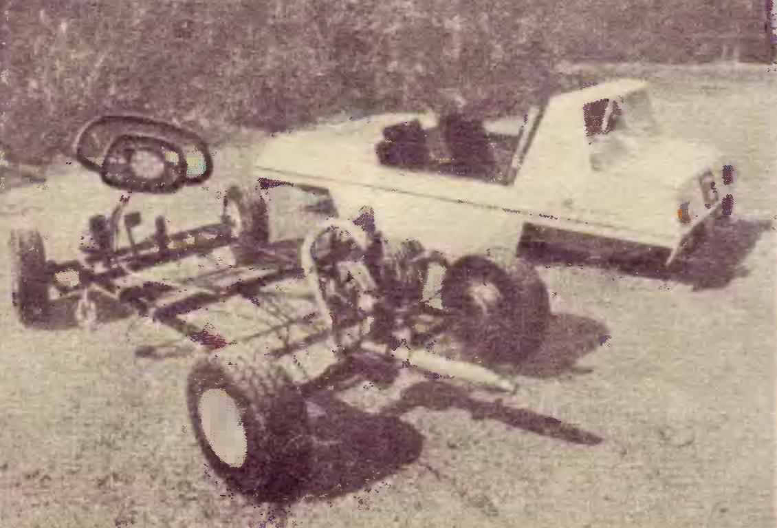
 Frame double machine, dubbed “mouse”, welded from thin steel tubes. Front axle (Fig. 3) assembled from beams, two eyes and swing units of the front wheels. Axle are the axle adapted to pivot the sleeve at an angle of 98 ° and welded to it. Pivot arm has a bend of sheet steel with thickness 1.5 mm; pivot bushing it is attached by welding at an angle of 110°. Ring tail joints at the ends of the swivel levers are cut from steel pipe ø 12 mm.
The pivot bushing is provided with bronze bearing liners, through which is passed a pin pivotally connecting the sleeve with the lug of the front axle.
Wheel — steel, turned. In each are placed on two bearings (202 and 201), closed Salnikova washers.
The hub is fixed on the axis of the axle nut. Between the bearings inserted spacer.
Wheels are assembled from halves stamped from sheet steel S=1.5 mm on a lathe using the mandrel and roller. For fastening the disc to the hub is welded to the last heads of the four bolts.
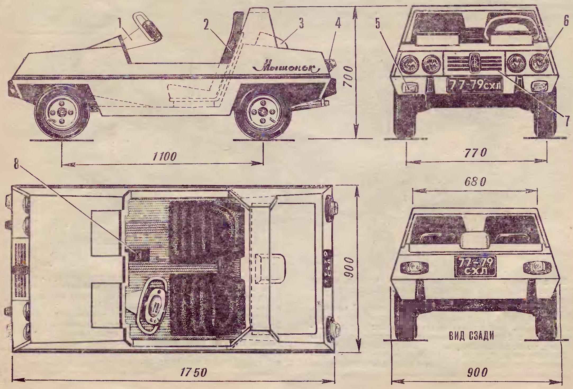
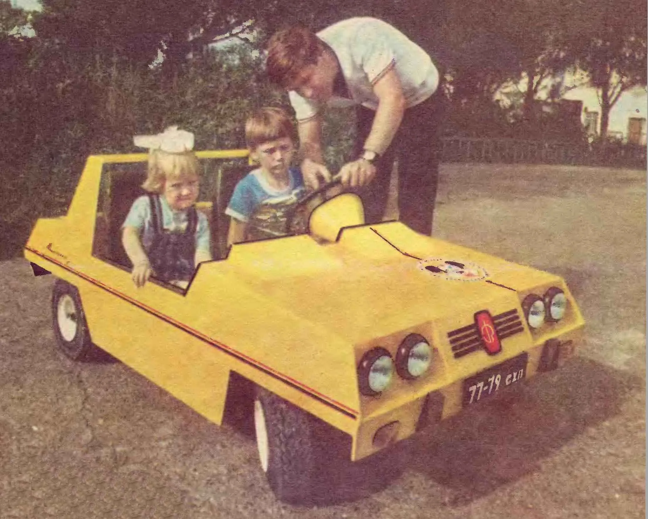
Fig. 1. Car “Mouse”:
1 — tie bar,
2 — seat,
3 — air inlet,
4 — lights
5 — front “blinkers”,
6 — lights,
7 — grill,
8 — cover the control wires.
The eyelets of the front axle are connected with the beam at an angle of 98° with the kingpin tilted back 12°. Accuracy of setting angles during welding provided the use of templates and spacers.
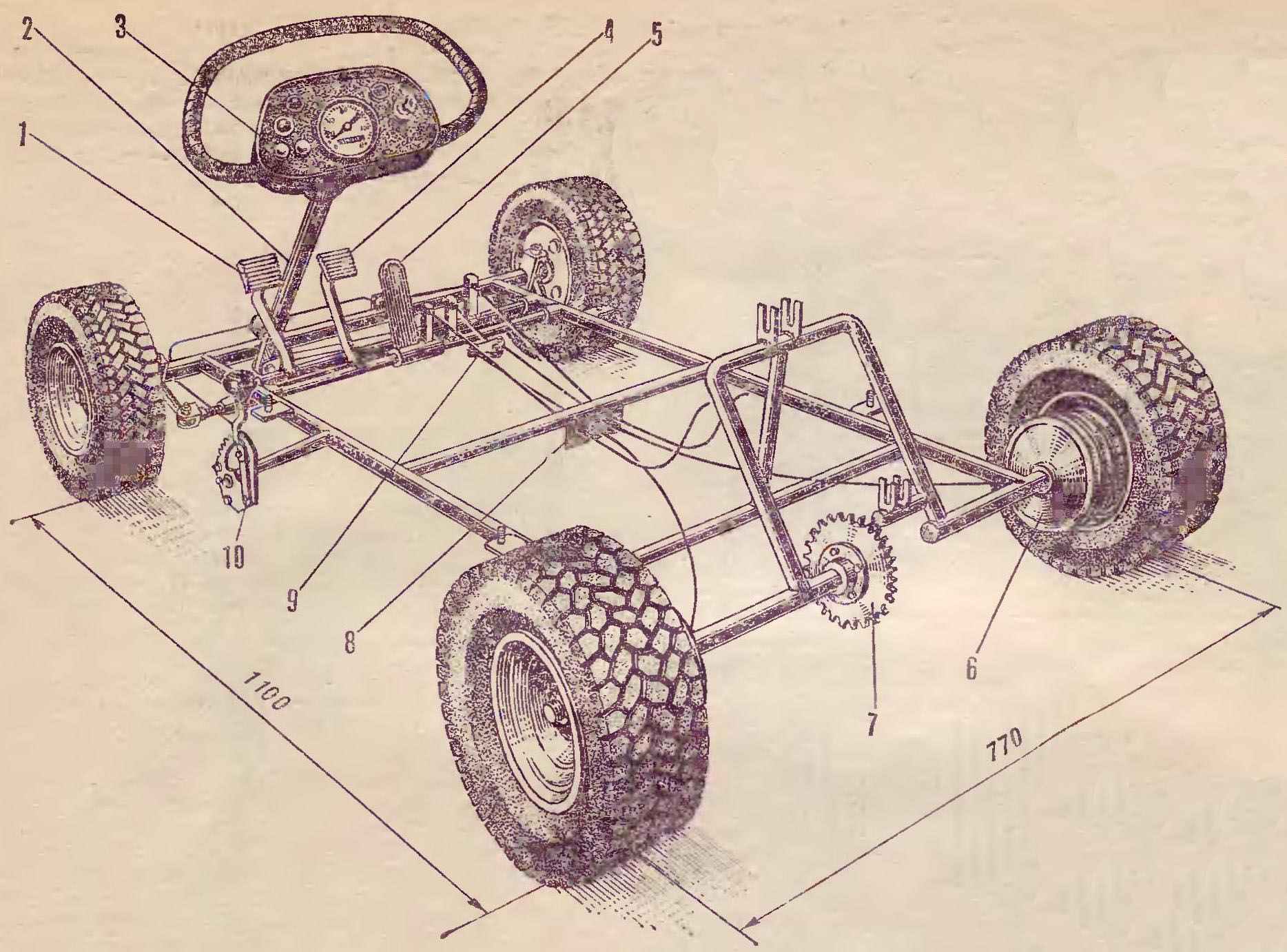
Fig. 2. The layout of the car:
1 — clutch pedal
2 — steering column,
3 — tie bar,
4 — brake pedal,
5 — pedal throttle control carb
6 — brake drum,
7 — star
8 — adjustable stops control cables,
9 — differential unit brake drums,
10 — lock the clutch pedal.
Rear axle composed of lead (Fig. 4) and slave (Fig. 5) Promoscow. The basis of the first steel tubular beam, it is welded bearing support. To a support with three bolts attached to the brake disc. The axle shaft is inside the beam half-bridge; hub, machined from steel, is pressed onto the shank axis, and in addition, the fixed key and castellated nut. On the opposite shank half shafts with interference placed and fastened in the same way the flange driven sprocket. Itself a star (Z=30) is cut out from steel sheet of thickness 3 mm and three bolts provorachivaetsya to the flange.
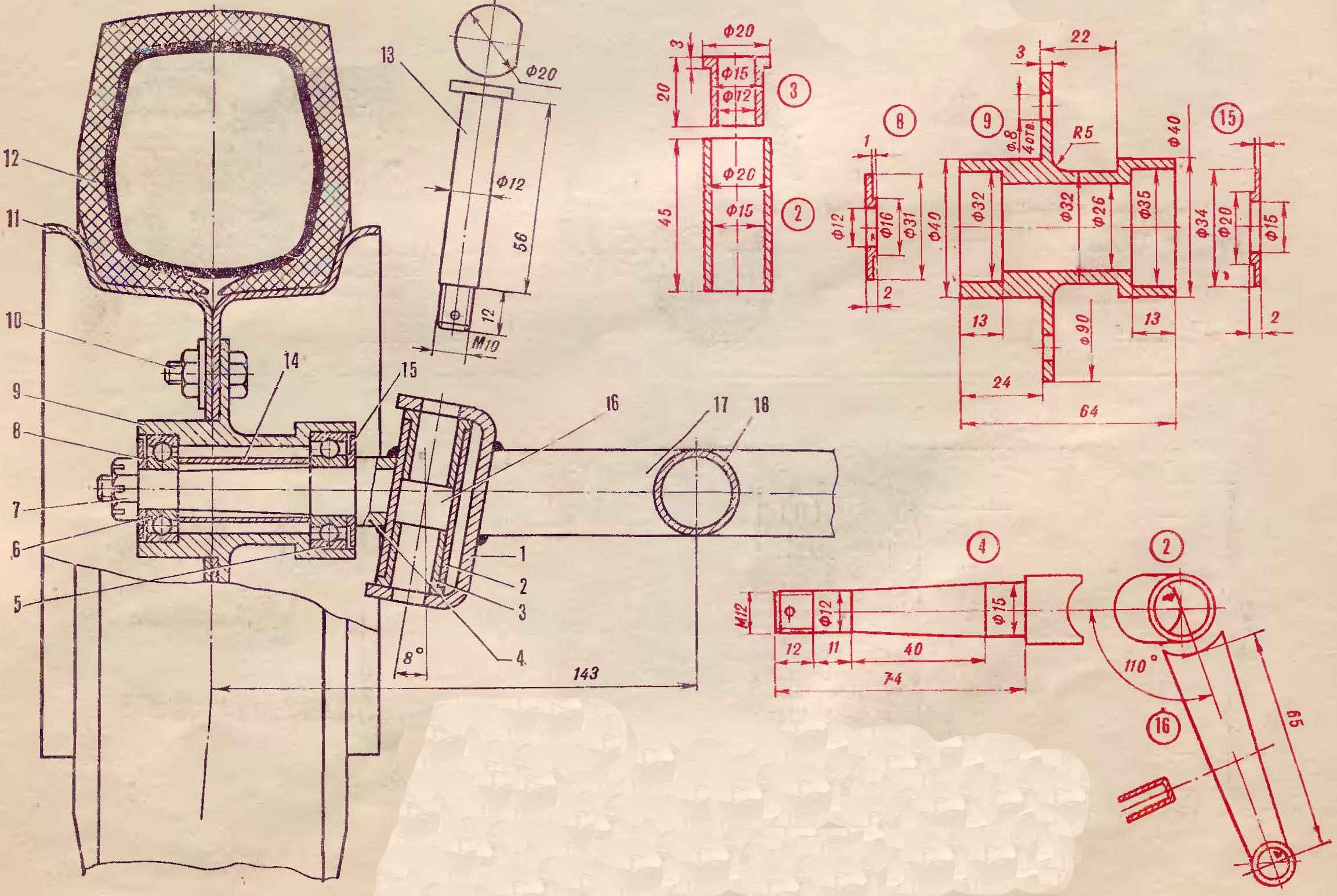
Fig. 3. Front axle:
1 — the eye
2 — pivot bushing,
3 — support sleeve,
4 — axle axle,
5 — the bearing 202,
6 — the bearing 201,
7 — nut M12
8, 15 — the packing washer,
9 — wheel hub,
10 — bolt M8
11—drive wheel
12 — bus-25 3,5X5,13,
13 — pin,
14 — spacer,
16 — swing arm,
17, 18 — I-beam frame.
The slave (right) half-bridge. Foundation — beam with welded flange for mounting a brake disk. The last is joined with a flange with three bolts. The wheel drive shaft is pressed into the beam of the half bridge and is secured by two through studs. On the axis there are two bearing — 202 and 201, 202 and the bearing outer ring pressed into a pre-bored hole in the brake drum, and a bearing 201 in the hole of the hub, which is connected with the brake drum with three bolts.
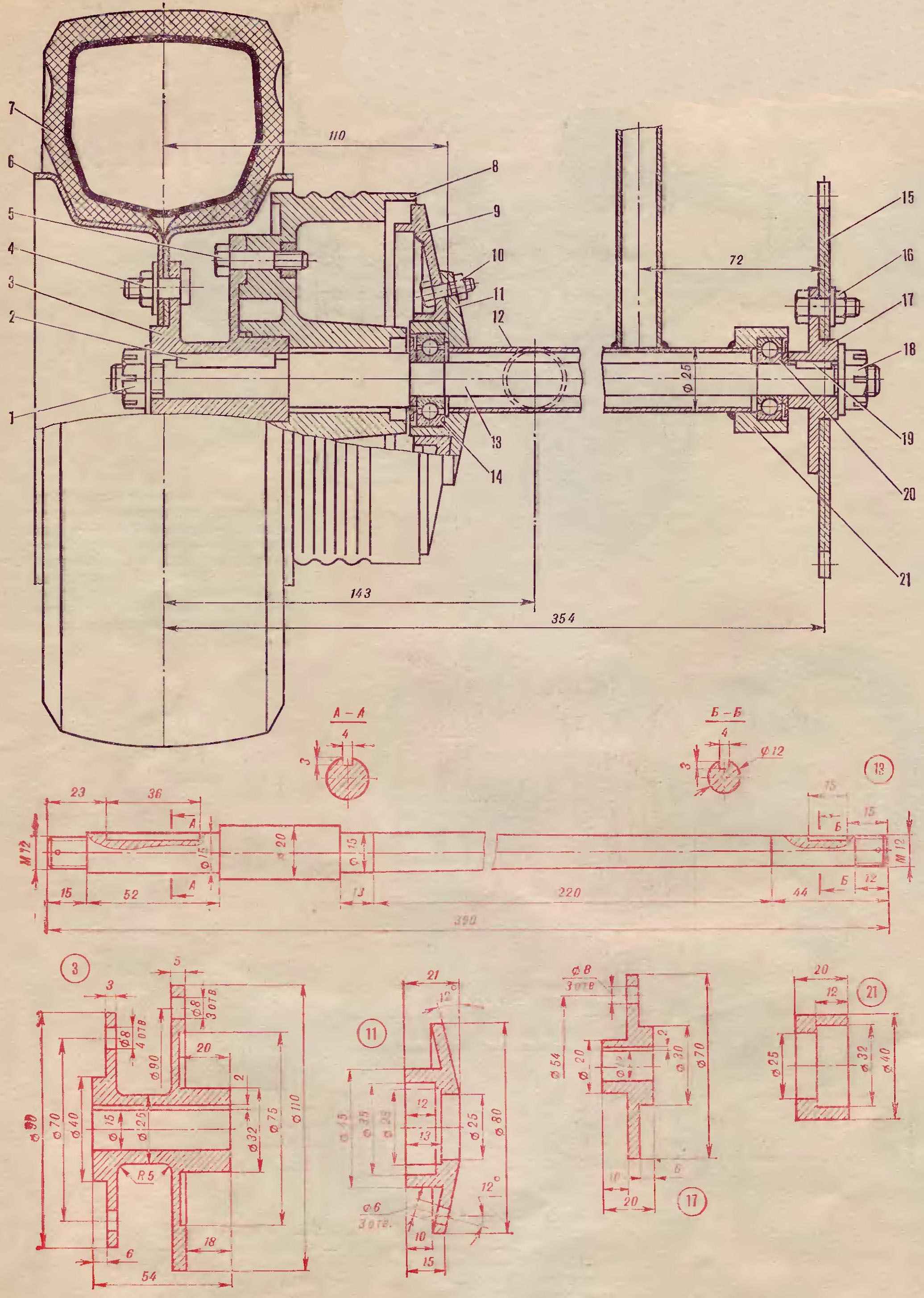
Fig. 4. Rear drive half-bridge:
1 — nut M12
2 — dowel,
3 — hub,
4 — M8 screws with cylindrical head,
5 — bolt M8
6 disc wheels,
7 — bus-28 3,5X5,
8 — brake drum,
9 — supporting the brake disc,
10 — bolt M6,
11 — bearing support,
12 — beam half-bridge,
13, the leading axis,
14 — the bearing 202,
15 — driven sprocket (Z=30),
16 — bolt M6,
17 — flange,
18 — nut M12
19 — dowel,
20 — the bearing 201,
21 — bearing support.
Engine “Mouse” by motorbike, type D 5.
Engine mount (Fig. 6) under the engine is welded from steel pipes external d18 mm. It consists of front support and rear racks to which are attached lugs cut from steel sheet. To the standard fixing points of the engine bolts attached to the brackets. By adjusting the tension of the chain — bolt, he started pushing the pin of the bracket moves the motor along the slots in the lugs in the vertical direction. The carburetor associated with the engine transition pipe, because the engine is flooded with ago. Fuel tank capacity of 2 liters is located under the hood.
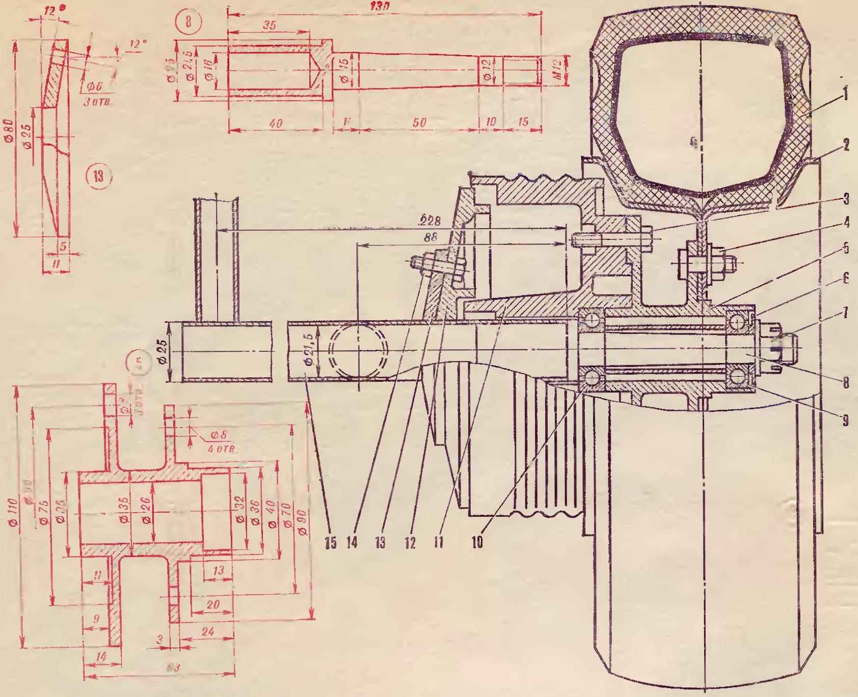
Fig. 5. Rear slave half-bridge:
1 — bus-28 3,5×5,
2 — disc wheels
3 — bolt M8
4 — M8 screws with cylindrical head,
5 — wheel hub,
6 — the packing washer,
7 — nut M12
8 — axis,
9 — the bearing 201,
10 — the bearing 202,
11 — brake drum,
12 — supporting the brake disc,
13 — mounting flange of the brake disk,
14 — bolt M6,
15 — rear axle beam.
Steering (Fig. 7). It’s main unit — steering column welded to the end of steering a plow, curved polutoratysyachnogo of the steel sheet. With the swing arm front wheel it connects rods. The upper end of the column ends closed steering wheel (pipe d12 mm). There is also a tie bar with the dashboard. Rotating the steering column in two textolite bearings: the first is mounted on the front beam of the frame, and the second on the counter. Both fixed steel plates. Longitudinal” offset to prevent the thrust ring.
For adjusting the length of the tie rod have a threaded bushing.
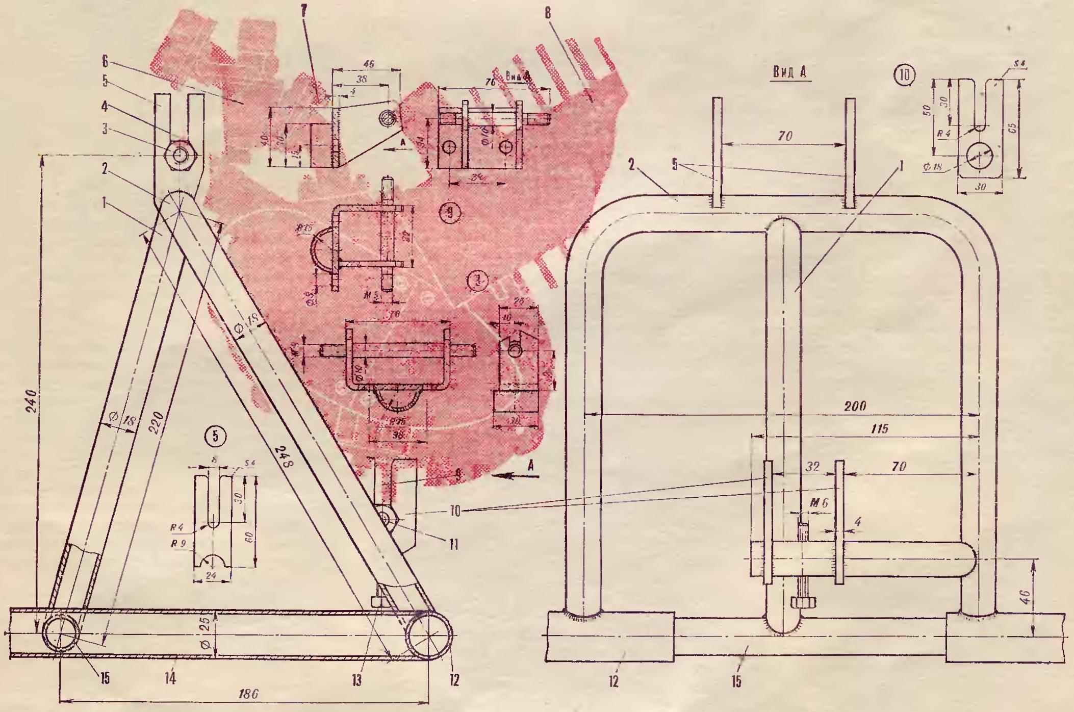
Fig. 6. Engine mounting:
1 — front support of the motor,
2 — back front engine mounts,
3 — nut M8
4 — front bracket engine mounts,
5 — front eyelet
6 — carburetor-To-346,
7 — a reducer,
8 — engine D-5,
9 — rear bracket, engine mounts,
10 — rear eye,
11 — nut M8
12 — rear axle beam,
13 — adjusting bolt M6
14 — spar frame,
15 — rear crossmember of the frame.
All steering joints have rubber bushings. The steering angle is 300.
Clutch pedal and brake (Fig. 7) — steel pipes d12 mm. Shafts of pedals enshrined in textolite bearings mounted on the front crossmember of the frame and the side members. Gas pedal — three-millimeter steel plate welded to the bushing. Its axis is the shaft of the brake pedal.
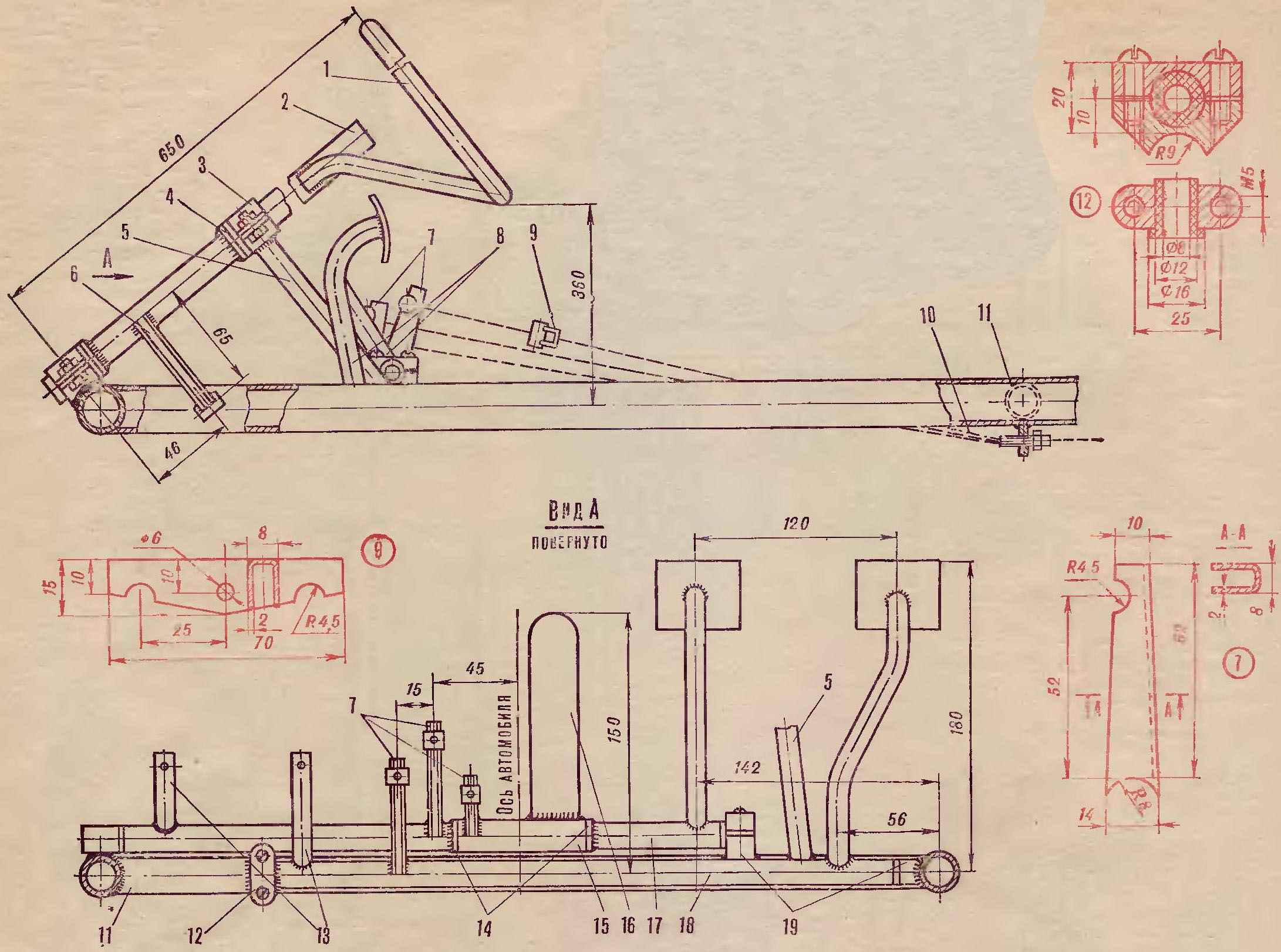
Fig. 7.The controls of the car:
1 — steering wheel
2 — steering column,
3 — the bearing housing,
4 — snap rings
5 — pillar steering column,
6 — a Pitman arm
7 — levers of the pedals,
8 — brake pedal and clutch
9 — equalizer tension of the brake cables
10 — adjusting stops
11 — front cross member frame
12, 19 — of bearing housings,
13 — grommet mount backup pedals,
14 — ring,
15 — bushing of the accelerator pedal,
16 — the accelerator pedal,
17 is a shaft of a brake pedal,
18 — shaft of the clutch pedal.
Control cables — motorcycle, adjustable threaded stops the drive Cables of the brakes connect to the brake drums using a tension leveler In the car extra pedals for the instructor, for which the shafts of the pedals welded steel sleeve.
 The body of the car hardwood. I collected it on the glue and screws with 7 mm plywood (cladding), two longitudinal rods and two transverse frames. The outside is plastered with fiberglass on epoxy resin with subsequent caulking, priming and painting nitroenamels. The front wheels inside closed flaps of sheet steel with a thickness of 1 mm. Seat fabricated from pipe d15 mm and plywood on top covered with foam rubber and artificial leather. Provided even adjusting the seat position depending on the height of the driver and passenger: the longitudinal movement of chairs along the guide rails fixed in the selected position by the stoppers.
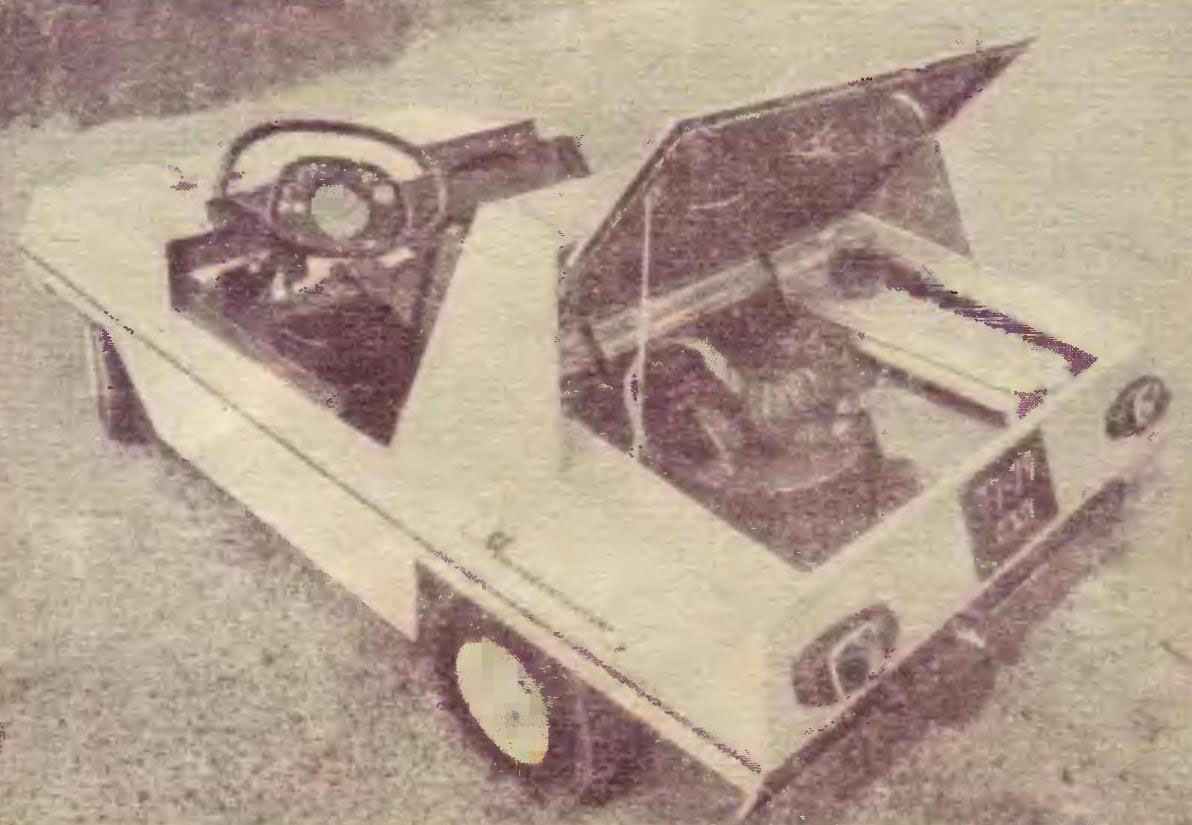
The electric car is powered by the battery collected from the twelve elements of the “373”, this four lights (on bike) and front position lamps and direction indicators (motorcycle type), and brake light, and sound.
The dashboard, on which are mounted speedometer, headlight switches and flashers turn, signal button and indicator lamp, mounted in the steering bar. The last case is laminated on the blank papier-mâché and then hardened the surface with fiberglass.
Frame and car body are connected by four threaded studs, so to break the machine, simply Unscrew the four wing nuts, disconnect the fuel line and electrical connector.
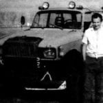
In conclusion I will add, I started work on the car in 1977 and finished in 1979. Total time spent on construction (not including turning), about 380 hours. The little car turned out, I think, durable, in any case, during the operation of any trouble it has not happened.
Recommend to read
 “MOSKVICH”-THE ROVER
Dear editors of the journal "modelist-Konstruktor". Your journal I read from 1988 (I'm now 33). By profession I am a mechanic, own a welding business, and to all, a big fan of... BURAN PLYUS
In our home the garage there is a well-worn snowmobile "Buran". I'm not going to Express their attitude to it in General, because the views of the owners on this issue diverge. However,...
