MINI-MOKIK: SCHOOL OF DESIGN

MINI-MOKIK: SCHOOL OF DESIGN

Small cars and motorcycles always aroused great interest among Amateur designers. This is understandable: a vehicle having a small size and weight, low fuel consumption, well fit into the traffic flow of city streets, convenient to maintain and repair and durable enough, can not to attract attention, and, of course, primarily a teenager.
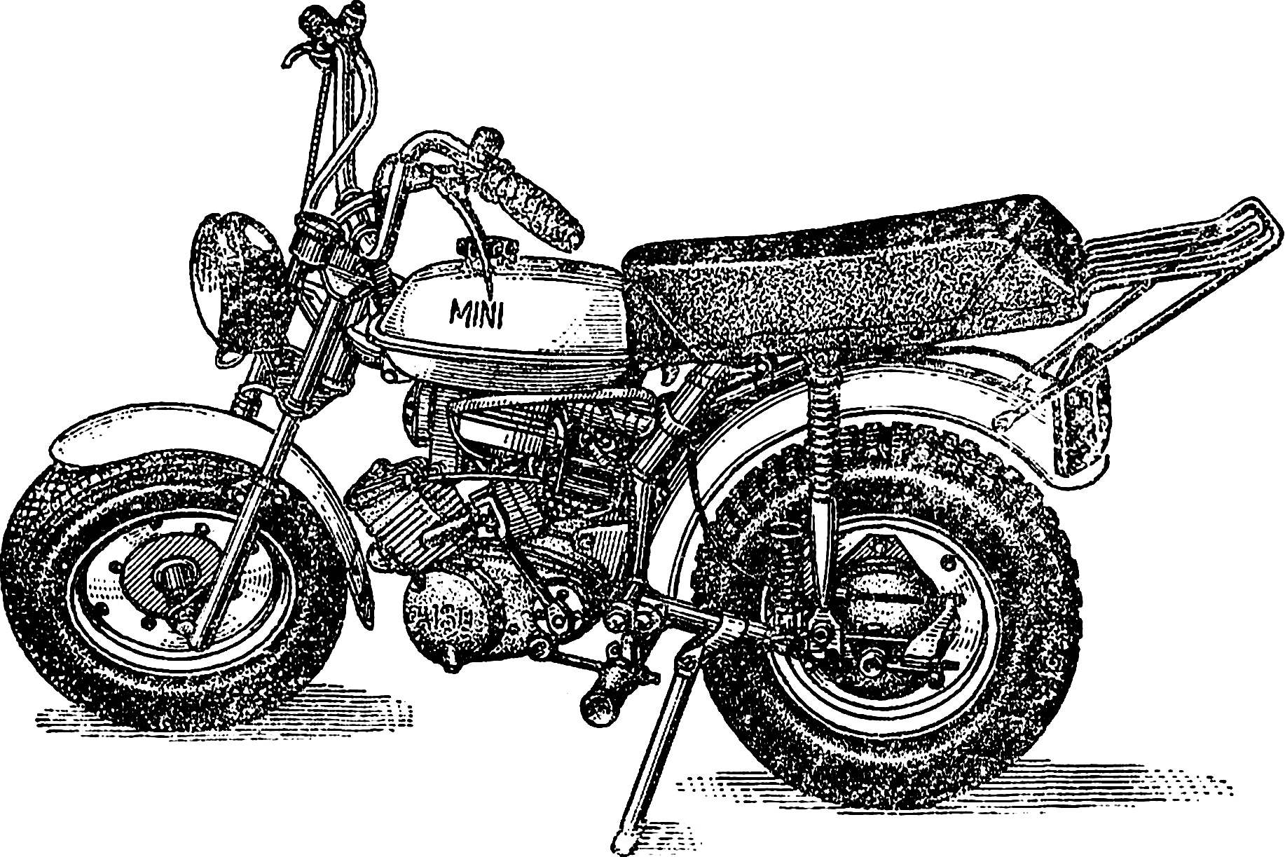
All this was the reason that the miniature vehicles has become a major hobby of boys in our children’s autoconstructor lab “Dare, create, invent!” in the House of young technicians of regional trade Union Council of the city of Vologda. I want to introduce the readers of “M-K” with one of the most successful of our research — a mini-mokik engine šiauliai plant “Vairas”, as well as the main stages of the design and some technological methods of production of individual nodes.
 
Of course, there is no point to do absolutely all the details of their own — industry produces enough finished products, suitable for equipping such machines. This wheels complete with discs and brake drums, pendulum, fork, chain, brake light switch, handles, clutch control and a brake on the front wheel (scooters “True”, “Tula” or “Tourist”) as well as components from the mopeds of the “Riga-22” — engine V-50 gas tank with fuel tap and cap, parts of front fork, rear shock, handlebar, grip throttle, ignition coil, muffler, rear wing, sound an alarm, toggle switch lights and vostokfilm. Besides mokik set fog lamp, truck rear lamp, which is used as an additional on cars.
Fig. 1. Mini-mokik engine V-50.
Fig. 1. Mini-mokik with V-twin engine 50.
 
So most of the details of industrial production. We only had to make the frame, extend the front fork and taking a seat. But this does not mean that design and make mokik is easy and simple. This work includes a number of stages, and, in our opinion, to properly design such a machine is no easier than, for example, a mini car.
 
The first step. It can be called conceptual design phase. All the plotting is best done in the same scale 1:5 — it is more suited for mokiki.
 
First of all, watertite all standard components and parts that are at your disposal. To assemble the machine from recommend paper silhouettes of parts and assemblies on a flat sheet.
 
The design of the transmission should be taken into account that the axis of the drive sprocket and the axis of swing of the pendulous fork should be placed on the same line — otherwise the chain tension when motion will constantly change.
 
To find the optimal variant of layout, make a sketch (you can use translucent tracing paper or glassine paper), adding the image parts to be designed independently. Suggest to depict several layout options to choose the most appropriate.
 
Now go on to detailing Assembly drawing — here already it is desirable to draw parts in actual size. Thus it is necessary to carefully coordinate the dimensions of the parts, and take into account the connection dimensions of finished components and assemblies. And only after checking the compatibility and interaction of the elements of mokik, proceed to the second stage.
 
The second stage is the direct manufacturer. In this case, was self-made frame, front fork, front mudguard and some other details.
 
The most difficult and responsible element of mokiki — frame. First the sheet of plywood we have created a kind of Plaz — side view in full size. In the future, all frame parts customized, and then welded together using plasma as a sort of template.
 
Fig. 2. Frame of mokiki.
Fig. 2. Frame mokik:
1 — steering column 2 — spinal tube, 3 — many, 4 — upper mounting bracket engine, 5 — bracket, fuel tank, 6 — seat tubes, 7 — vertical stand, 8 — brace the seat tube, 9 — seatpost bracket, 10 — axle rear shock absorbers, 11 — mounting bracket coil ignition, 12 — bracket Vozduhoflotsky, 13 — crossbar of the pendulous fork, 14 — step, 15, 16 — mounting bracket mud flap, 17 — cheeks crossmember of the pendulous fork, 18 — rear bracket fastening of the motor, 19 — bracket audio signal.
 
Fig. 3. The mutual position of the pendulum fork and the engine.
Fig. 4. Fork.
Fig. 4. Fork:
1 — feathers plugs, 2 — bearing elements, 3 — plate bridge, 4 — corners strengthen the bridge, 5 — bracket lights, 6 — bracket mud flap, 7 — cheek pen plugs 8 — Bush.
 
Fig. 5. The gearshift mechanism.
Fig. 5. The gear:
1, 11 — front and rear lift pads, 2 — front arm, 3 — rope lever 4 — screw 5 — spring 6 — ball, 7 — axis, 8 — bushing fixing, 9 — clip 10 — back lever.
 
Frame mokik consists of conventional welded pipes with external Ø 34 mm. and 21 To reinforce the steering column is a steel scarf she designed for mounting the fuel tank. To the ridge of the frame is welded also to the plate for installing the ignition coil, it has two holes drilled for fixing the block stabilizer of the engine.
 
For mounting the engine are the brackets, cut from steel sheet of thickness 2 and 3 mm. To the vertical rack frame welded section of pipe Ø 25 mm with flanges on the edges, this node is required for planting of the pendulous fork, and a kickstand from a pipe with a length of 410 mm and Ø 21 mm.
 
For fixing the upper hinge of the shock absorbers of the pendulous fork is designed axis — rod Ø 12 mm and a length of 260 mm, the ends of which are machined to a length of 40 mm and they tapped M10. Axis reinforced steel corner 25X25 mm. welded To the frame two area — they are attached to the seat and fuel tank.
 
Front fork of our mokiki is not quite normal. It is much broader than the standard moped, and feathers it is a “former” carrying elements of the moped fork and bearing elements is a “former” fork feathers “Riga-22”. The extension of the fork used two triangular element from steel sheet of thickness 3 mm (the upper one is removable).
 
The front wheel is attached to the feathers with cheeks made of sheet steel, welded to the pipes. To these same tubes attached by welding brackets front fender, and the bridge — bracket headlamp mounting.
 
One of the most interesting nodes switch to the transmission. As you know, the engines of “V” or “W” this switch is manual and it is much less convenient than the foot, traditionally used on most motorcycles.
The mechanism is foot-operated switch was very simple in design and in manufacture. He is a holder welded to it details of — the front and rear arms with support sites, a lever to secure the shift cable and grommet fixing. Inside the latter are steel ball, spring and screw — they provide a clear locking of the lever in all three positions — first gear, neutral and second gear.
 
Handle “gas” — from moped, grips, clutch control and front brake of the scooter. The brake pedal was first made, and then we replaced it with a pedal of the motorcycle “Minsk”.
 
And the last one. Our machine is double, so the frame is fixed footrests for the passenger or two cut tubes with a diameter of 21 mm and a length of 125 mm. All foot pegs with rubber cushions motor.
 
Mini-mokik easy to control, convenient and, we think, has a number of advantages compared to the industrial counterpart of the Riga manufacture.
 
KRYLOV, Vologda

Recommend to read

  • BOEING VERTOL CH-46BOEING VERTOL CH-46
    Boeing Vertol Company was founded in August 1940 by F. PIASECKI, who became the chief designer and Chairman of the Board of the company. During her activities released more than 2,500...
  • PWPTR FOR KITCHENPWPTR FOR KITCHEN
    If you forgot how baked waffle cake, preparing jellied fish or fried chicken Tabaka, it does not matter. Grab a cookbook, find the desired recipe and cook what you will. However, when...