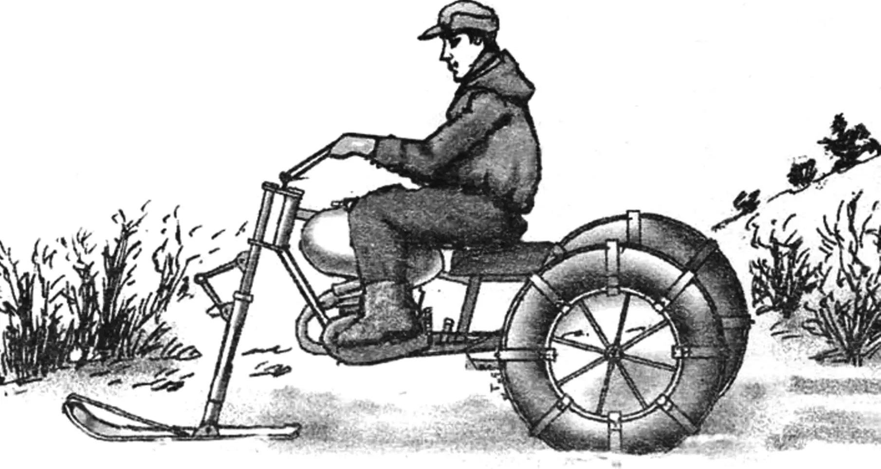
Readers of the magazine “Modelist-Konstruktor” are offered a simple wheel-and-ski snowmobile designed for travel along snow-covered country roads and even open snowfields.
The snowmobile is three-point, with two rear driving pneumatics and one steerable ski at the front.
Compared with other machines of this type, the snowmobile’s design is extremely simple, which makes it possible to build it even in a home workshop.
The ease of construction is ensured primarily by the fact that a “Minsk” motorcycle is used as the basis of the design. In this case, the power unit (engine with gearbox), frame, fuel tank, and seat underwent practically no modification. Other units, such as the handlebars or rear fork, were only modernized and adapted to the new design.
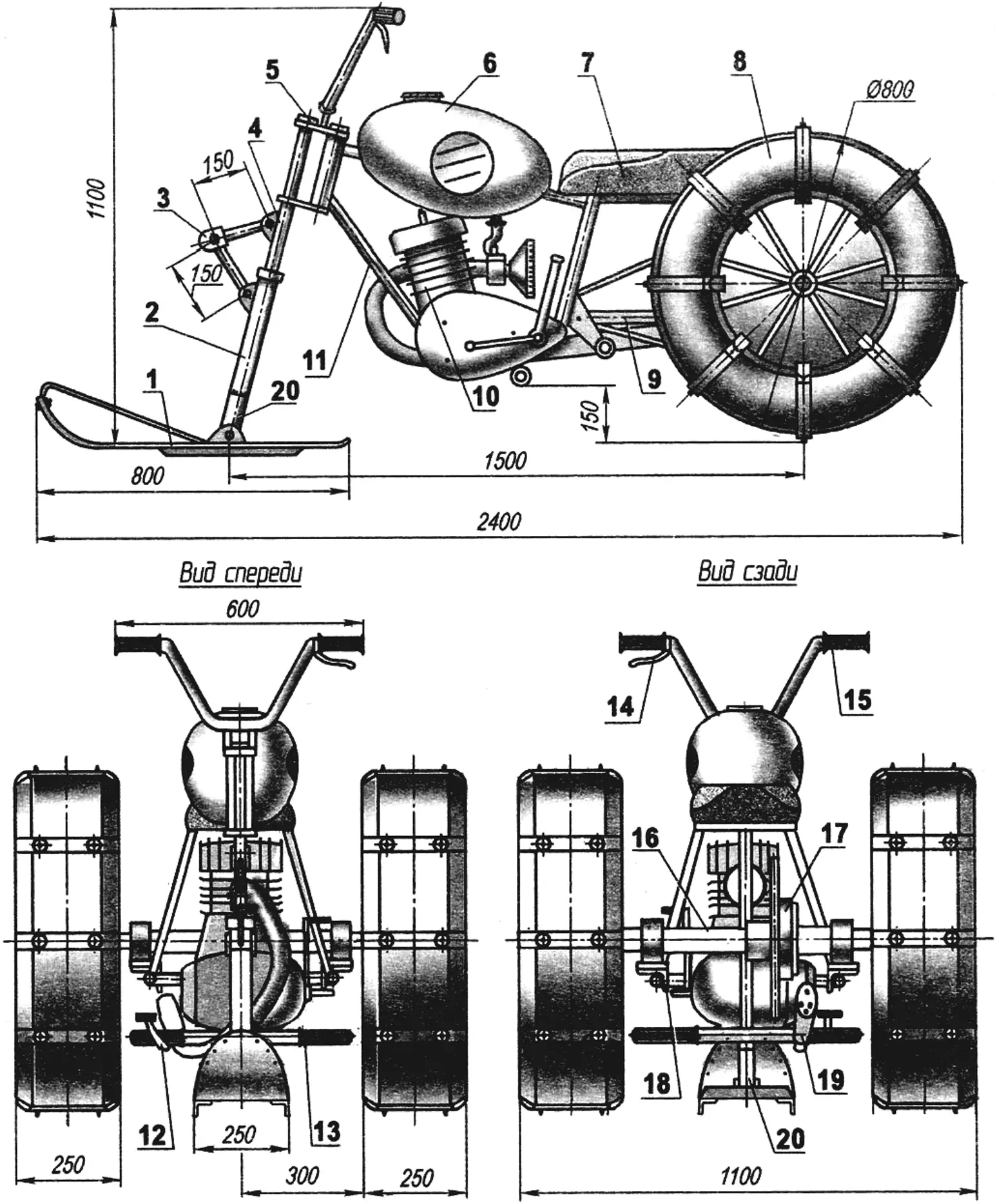
1 — support-steering ski; 2 — lower leg of the telescopic shock-absorbing steering column; 3 — connecting mechanism of the steering column legs; 4 — upper leg of the steering column; 5 — steering bridge; 6 — fuel tank; 7 — seat; 8 — driving wheel (pneumatic, 2 pcs.); 9 — rear fork; 10 — engine; 11 — frame; 12 — brake pedal; 13 — footrest; 14 — clutch release lever; 15 — throttle grip; 16 — rear axle; 17 — driving sprocket and brake unit; 18 — fork extension; 19 — muffler; 20 — lower leg extension of the column with bushing
Fully homemade are the support-steering ski and the wheels of the support-driving pneumatics. Descriptions of the ski and wheels have appeared more than once on the pages of “Modelist-Konstruktor,” in various versions. Readers of the magazine who decide to build a similar snowmobile have plenty to choose from. Therefore, I will not give a detailed description of either the design or manufacturing — this is clear from the drawings provided.
The rear axle is also homemade, but it contains no special design solutions, unless one counts the fact that it is simplified to the limit. It has a one-piece (welded) driving shaft (rather than two half-axles, as usual), and both wheels are driving (without a differential). On a slippery snow-covered road, such a design replaces differential lock, improving cross-country ability. True, maneuverability is reduced (steering in turns is more difficult), but for better grip with the road — or rather with the snow cover — two side cuts were made on the steering ski from a duralumin angle 35×35 mm.
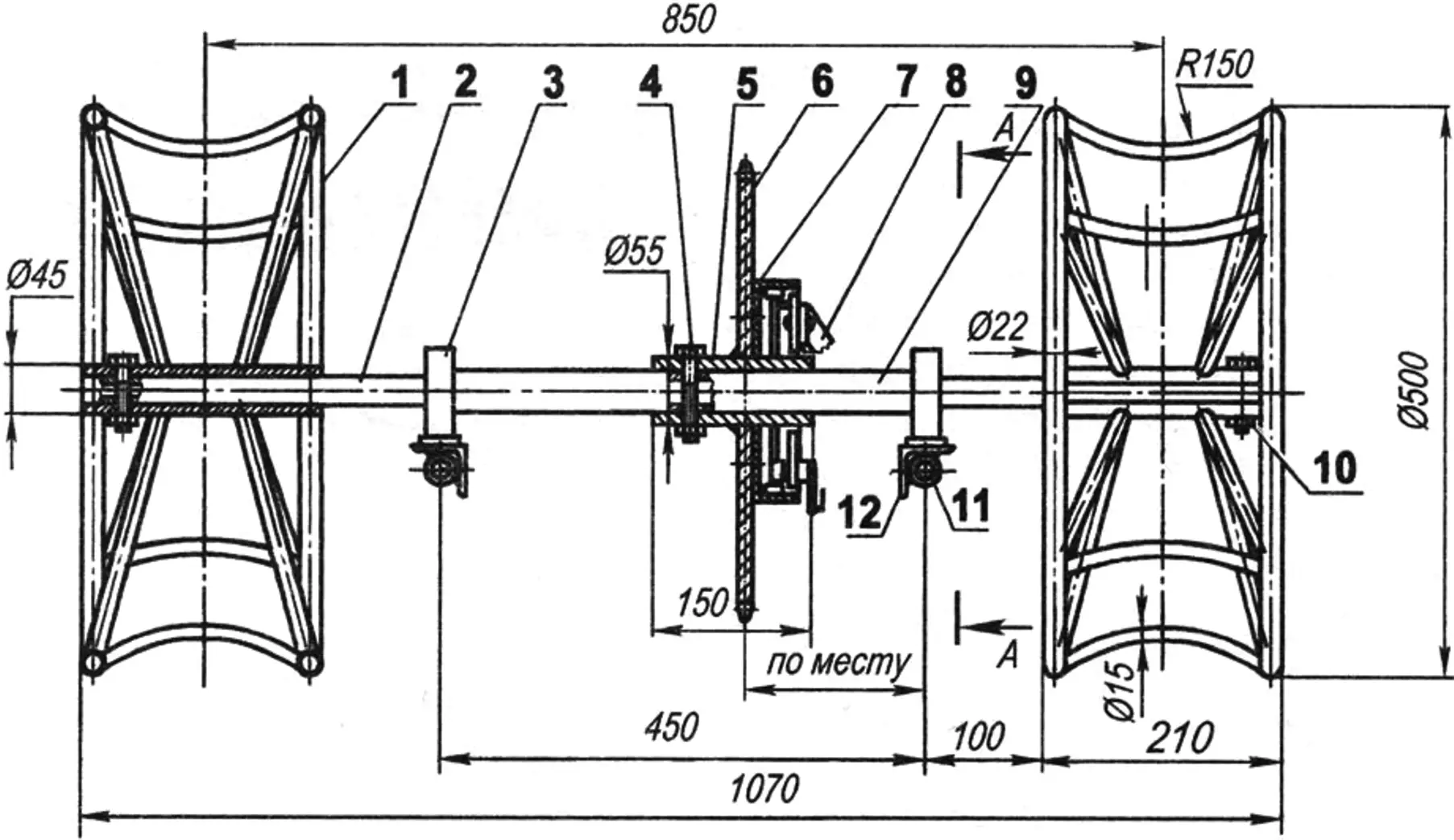
1 — pneumatic wheel frame; 2 — driving shaft end (2 pcs.); 3 — bearing unit (2 pcs.); 4 — driving sprocket bushing pin (M8 bolt); 5 — bushing; 6 — driving sprocket; 7 — brake device (from the “Muravey” cargo motor scooter); 8 — brake device mounting bracket (steel plate); 9 — driving shaft; 10 — wheel bushing pin (M8 bolt, 2 pcs.); 11 — fork (from the “Minsk” motorcycle); 12 — fork extension (50×50 angle, 2 pcs.); 13 — brace (Ø15 tube, 2 pcs.); 14 — drive chain (from the “Minsk” motorcycle, t = 15.875); 15 — brake drive rod; 16 — bearing housing (2 pcs.); 17 — bearing 80206 (2 pcs.); 18 — bearing housing base
The driven (large) sprocket of the chain drive is welded to the hub bushing, fitted on the shaft and secured on it with a pin-bolt. In this case, it is necessary that the position of this sprocket coincide with the plane of rotation of the driving sprocket on the output shaft of the power unit. The brake drum is also secured on the driven sprocket.
Chain tension is adjusted by moving the shaft and fastening the housings of its bearings on the angular extensions of the rear fork legs. By the way, instead of shock absorbers (for lack of them), tubular braces were welded to this fork, and low-pressure pneumatics provide quite good cushioning.
The pneumatics consist of chambers from tractor cart wheels, fitted on frame disks and “shod” in treads made of conveyor belts. The transverse and longitudinal treads are joined with bolts, whose high protruding studs serve as ground grips.
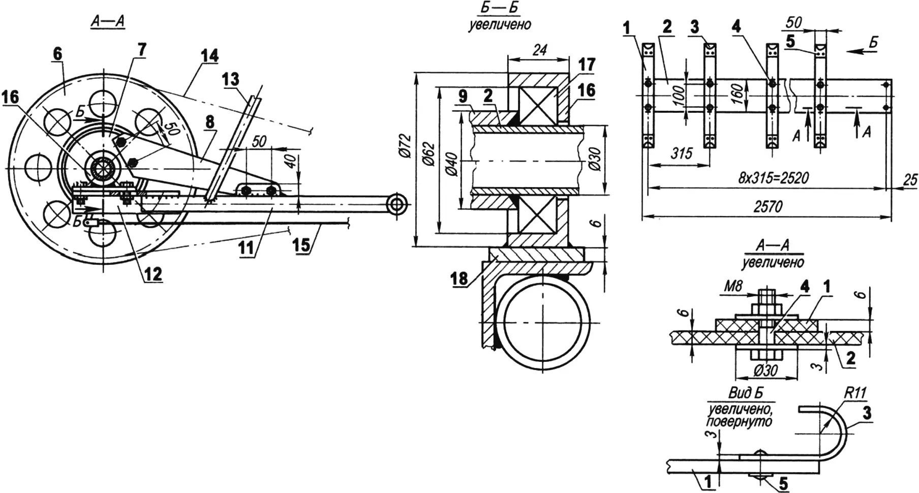
1 — transverse tread (conveyor belt, strip 50×6, 8 pcs.); 2 — longitudinal tread (conveyor belt, strip 160×6); 3 — hook (steel strip 50×3, 16 pcs.); 4 — M8 bolt with two wide washers (16 sets); 5 — rivet with backing wide washer (steel, 32 sets)
Torque is transmitted from the power unit to the mover by a chain drive with a gear ratio of 3.5 (the driving sprocket on the output shaft of the power unit has 8 teeth, and the driven one on the rear shaft has 28 teeth). The chain is a motorcycle chain with a pitch of 15.875 mm. The sprockets have the same tooth pitch.
As for the steering column, I think it is of a rather original design; at least, I have not seen similar ones. The column is made from the front shock-absorbing fork of the “Minsk” motorcycle. In this case, only one leg of the fork was left, without the cover, and on the lower and upper connecting bridges those parts to which the second leg was attached were cut off as unnecessary. An extension made of the same tube was welded to the lower end of the remaining leg, and a transverse bushing for connecting the steering ski was welded to the extension.
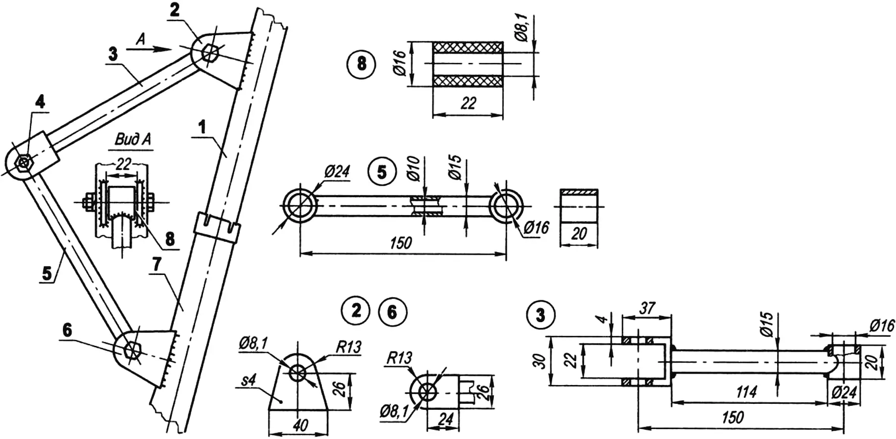
1 — upper leg of the column (from the “Minsk” motorcycle); 2 — lug of the upper leg (steel, sheet s4, 2 pcs.); 3 — upper lever (steel); 4 — axle (M8 bolt, 3 pcs.); 5 — lower lever (steel); 6 — lug of the lower leg (steel, sheet s4, 2 pcs.); 7 — lower leg of the column (from the “Minsk” motorcycle); 8 — bushing (caprolon, 3 pcs.)
As was said, the front column is shock-absorbing, and therefore its load-bearing (upper) tube not only slides in the lower one, but can also turn freely and even rotate in any direction. In this position, steering the ski from the handlebars is, of course, impossible. To make this possible, a transition bridge had to be made. The bridge is a simple mechanism consisting of two levers hinged together. The free end of one lever is connected through a welded lug to the load-bearing upper tube, and the free end of the other lever is connected in the same way to the sliding lower tube.
The bridge allows the shock absorber to work freely, but prevents the column tubes from turning relative to each other when the direction of travel changes.
The maximum speed of the snowmobile does not exceed 50 km/h. But it probably does not need more. What is far more important for it is high torque (tractive effort) on the driving wheels, and this was ensured. Since the snowmobile is relatively light, the engine power (10 hp) is enough to climb fairly steep slopes, as well as to cross drifts on winter roads and open snow. In addition, the snowmobile can tow a skier or light sleds with a load of up to 100 kg.
“Modelist-Konstruktor” No. 2’2008, A. MATVEYCHUK
Recommend to read
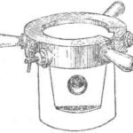 THE HELM FOR THE REPAIRMAN
It's mind typically "ship" device is intended for other, ground targets, Kuibyshev innovator N. Gerasimov developed it to help those who are engaged in the repair of automobile engines. ...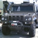 ARMORED CAR IVECO UNDER THE BRAND NAME “LYNX”
Cars, army UAZ-29661-vehicle with engine ZMZ-5143 98 HP and an elongated UAZ-2966 motor 9МЗ-4219.1 84 HP, which in the early 2000s were equipped with the Russian army, created on the...
