The magazine “Modelist-Konstruktor” has already described motor winches more than once — fascinating soil-cultivation mechanisms that have been gaining increasing popularity among amateur designers in recent years. And indeed, the merits of this excellent device are indisputable. The point is that a winch (by the way, one of the oldest mechanisms in the history of civilization), unlike self-propelled soil-treatment units, directs its power toward creating tractive effort.
This publication presents a version of the simplest motor winch.
The basis of the motor winch is the V-50 — a fairly common engine of about two horsepower, found on most “heavy” mopeds such as Karpaty, Verkhovina, or Riga. Engines from earlier production runs will also do — Sh-58, Sh-62, and others.
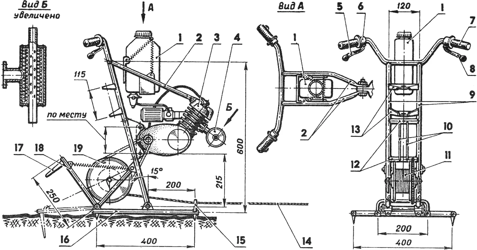
1 — fuel tank, 2 — braces of the front engine mounting unit, 3 — engine, 4 — muffler, 5 — clutch control lever, 6 — gearshift lever, 7 — carburetor throttle control grip (“gas”), 8 — hand brake lever, 9 — engine frame uprights, 10 — cheeks of the rear engine mounting unit, 11 — winch drum, 12 — engine frame crossmembers, 13 — fork bridges, 14 — cable Ø 5 mm, 15 — guide bracket (rod Ø 8 mm), 16 — support platform (pipe 22×2.5 mm), 17 — anchor, 18 — anchoring device, 19 — drive sprocket. (Left view: engine and anchoring device not shown).
The engine is mounted on an engine frame welded from sections of 30×2.5 mm steel pipe and parts made of sheet steel about 3 mm thick. A moped handlebar is attached to the top of the frame, and a support platform made of pipes with a drum and drive sprocket is attached underneath. At the rear, an anchoring device is hung on the support platform — a U-shaped sprung tubular frame with two anchors welded to it, made of sharpened steel plates resembling the blade of a spade.
A moped wheel hub is used as the winch drum, to which a duralumin cheek and a driven sprocket are attached — for example, a large gear from a road bicycle.
The fuel tank is a plastic canister with a capacity of 2…3 liters; a standard motorcycle petcock with a sediment bowl is located in its lower part.
The winch controls are the same as on any moped: on the right side of the handlebar — the throttle grip and hand brake lever (what it brakes will be explained a little later), on the left — the clutch lever and the moped gearbox switch.
The motor winch engine is fitted with a small homemade muffler welded from thin-walled pipes Ø 20 and 80 mm and a pair of end caps made of 2 mm sheet steel. Inside the muffler is tangled steel wire or thin swarf from turning. The device is extremely simple, but effective.
As a rule, the engine can run for quite a long time without forced cooling — especially if it is cooled by the wind. However, it is still more reliable to equip it with a forced air-cooling system. For this purpose, a V-belt drive pulley is secured on the flywheel rotor, and a bracket with a bearing housing is mounted on the cylinder head; two ball bearings are installed in it, and in them — a shaft with a pulley and a fan impeller.
Now a few words about how to use such a motor winch. It is placed at the edge of the plot and secured with the anchoring device. The gearshift lever is set to neutral, and the working tool (a small plow, hiller, or cultivator) is carried to the opposite end of the plot. It is best to work in pairs: one person operates the winch, and the other — the plow. Then the engine is started with the kickstarter and warmed up, the clutch control lever is squeezed, first gear is engaged, and then the lever is released smoothly. The cable begins to wind onto the drum, and the plow begins to move. That is essentially all there is to it. According to owners of similar motor winches, working with them is less tiring than with self-propelled units — motor blocks, motor tillers, or even micro-tractors.
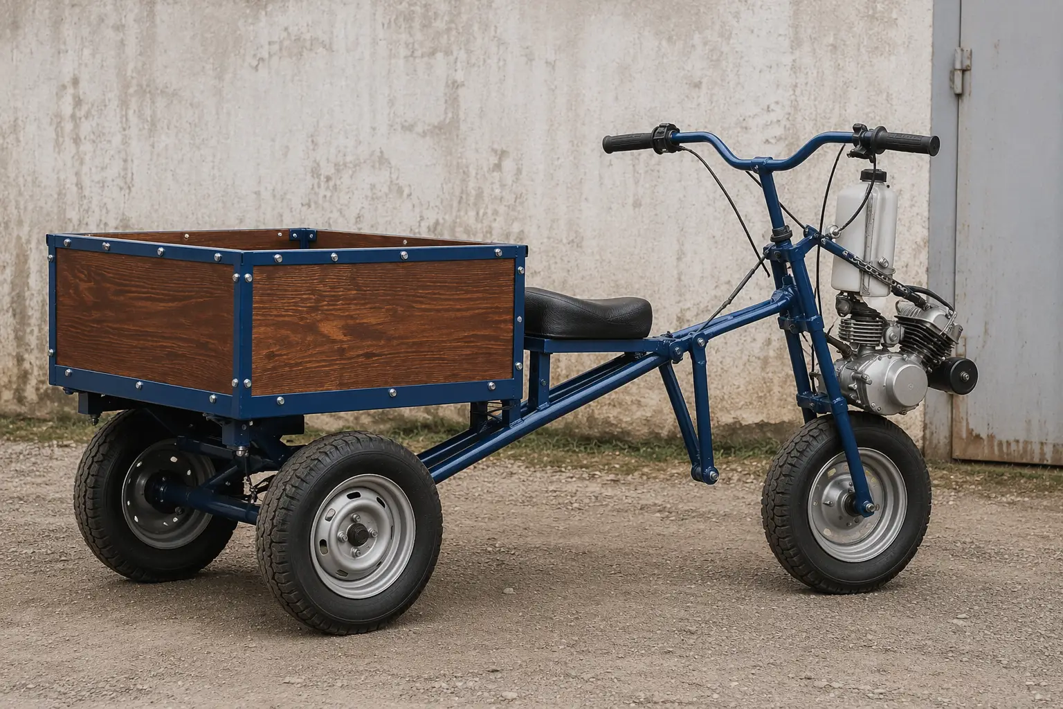
Of course, it would be irrational to use a convenient, compact power unit only for soil cultivation. Meanwhile, a motor winch is practically a ready-made motor block that can be coupled with other agricultural implements. And first of all — a cargo trailer that turns the motor winch into a motor truck. With such a “hybrid,” for example, the problem of delivering the motor winch to the work site is solved perfectly — it gets there quite independently and also carries a plow or cultivator, shovels, planting material, and so on. On site, the truck is converted into a motor winch in half an hour, and the planned work is carried out with its help. Then comes the reverse transformation, and the motor truck delivers home not only the driver and farm tools, but also, say, the harvested potato crop.
To turn the motor winch into a truck, it must be modified slightly. For this, instead of the support platform, a wheel with a driven sprocket (for example, from a mini-mokik) is installed on the frame, and the cable from the hand brake lever on the right handlebar grip is connected to the brake device on the wheel hub.
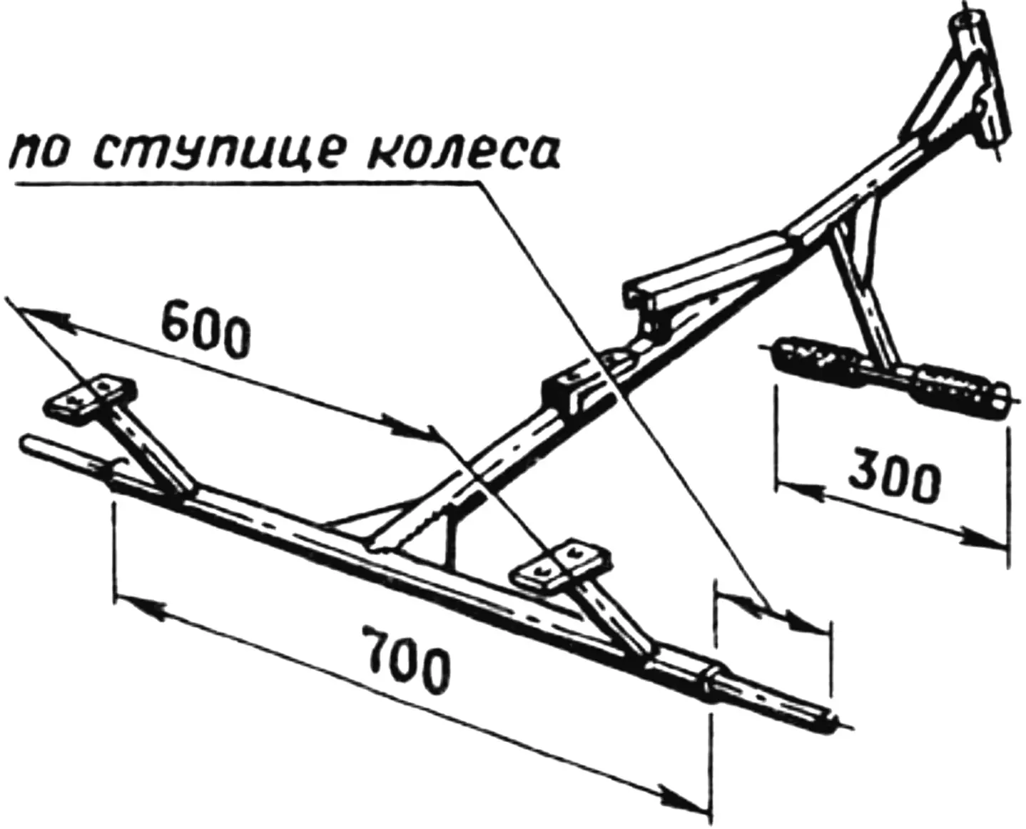
Now a cargo trailer must be made. It has a welded frame assembled from pipes of various diameters, a plywood body, and wheels from the same mini-mokik. The frame is coupled to the motor unit by means of a drawbar that has a steering column at the front end — a section of 30×2.5 mm pipe with a pair of bronze or textolite bushings. The other end of the drawbar is welded to the cart axle — a section of 30×2.5 mm steel pipe in which two half-axles are secured by welding; these are stepped shafts with threads on the outer ends. The half-axle diameter must match the wheel hub bearing diameter.
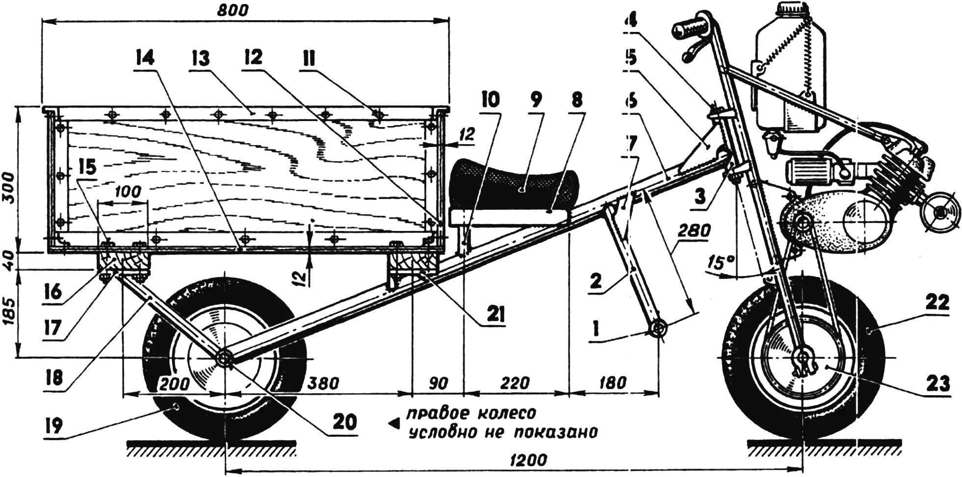
1 — footrest (pipe 22×2.5 mm), 2 — footrest bracket, 3 — steering column (pipe 30×2.5 mm), 4 — steering column axle (M12 bolt with nut and washer), 5,7 — gussets (steel 2.5 mm thick), 6 — drawbar (pipe 40×2.5 mm), 8 — seat bracket (channel 50x30x3 mm), 9 — seat, 10 — seat upright (pipe 22×2.5 mm), 11 — M6 bolt with nut, 12, 14 — body side and bottom (plywood 12 mm thick), 13 — edging (angle 40x40x2.5 mm), 15 — M8 bolt with nut and washer, 16 — body cradle (wooden block 40×100 mm cross-section), 17, 21 — support platforms for body cradles (steel 3 mm thick), 18 — brace (pipe 22×2.5 mm), 19, 22 — wheels, 20 — cart axle, 23 — drive sprocket of the front driving wheel.
Two braces with platforms for fastening the body cradles are welded to the cart axle; the cradles are cut from a wooden block with a 40×100 mm cross-section. The body is assembled from plywood blanks (12 mm thick) and steel or duralumin angles on M6-threaded bolts and nuts. The body is attached to the frame with M8-threaded bolts and nuts.
A seat and a T-shaped footrest for the driver are installed in front of the body. The seat can be taken from any moped, but it is not difficult to make one yourself from plywood, foam rubber, and artificial leather.
If the motor truck is also to be used at night, it is recommended to equip it with a headlight and rear marker lights, as on a moped, powered from the generator’s low-voltage winding.
It should be noted that the steering angle is about 90° to the right and left, so the motor block can turn around literally on the spot.
“Modelist-Konstruktor” No. 10’96, I. SOROKIN, engineer
Recommend to read
 SECRETS TIERNEY
In the fourth issue of our magazine published model glider of the world champion V. Extencive. Today we offer timesnow model champion of the USSR E. Verbitsky. She applied some new... CADILLAC V16 SPORT PHAETON
Not everyone knows that the name of American auto-mobile firm Cadillac was given in honor of the founder of the city of Detroit Frenchman Antoine de la Cadillac Mot. The first...
