Many imported bicycles with a large number (over a dozen) of speeds have now appeared on our market. But such machines probably only fascinate young people. Experts understand that it is still impossible to use all speeds to the full extent: it is not easy even to correctly select the right gear, and frequently switching them on the move is not only tiring, but also unsafe. After all, shifting is usually required in difficult driving conditions or on turns, when the hands must reliably hold the handlebar, and one of them has to manipulate the shifter at this time. As is known, cars have only 4-5 speeds, and even then drivers prefer to switch to automatic transmission.
Abroad, multi-speed hubs of the rear drive wheel (for example, with a planetary gearbox or hydromechanical) are produced, providing automatic and smooth change of the gear ratio. But their efficiency is significantly lower than that of a conventional chain drive. Undoubtedly, riding and walking on a bicycle with such a hub is carefree and pleasant, however, in tourist trips or sports competitions, significant losses of muscle energy are undesirable, that is, hubs with such automation are unacceptable.
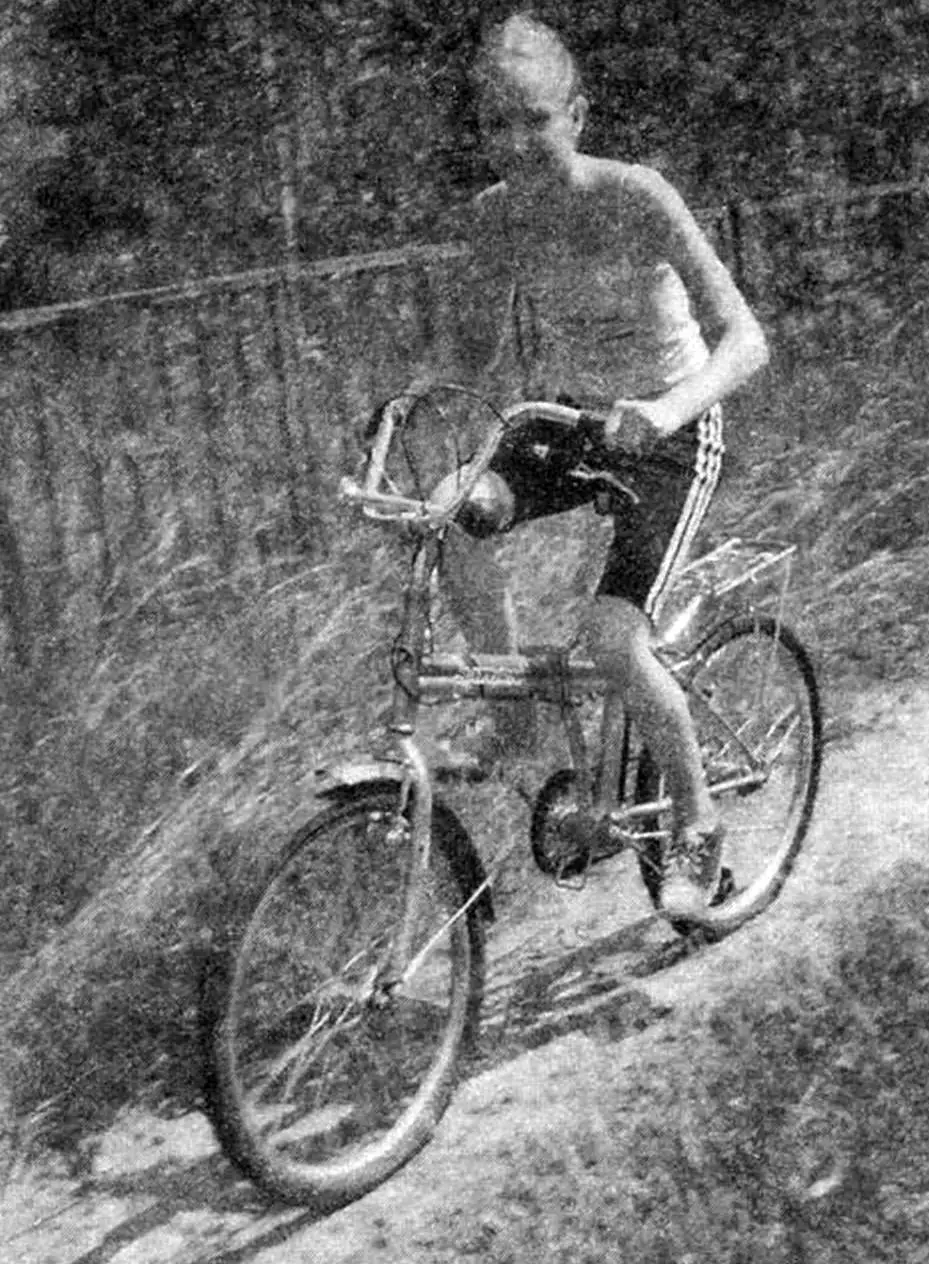
I have designed a multi-speed rear wheel hub with automatic gear shifting, which practically has the same efficiency as standard hubs of touring and sports bicycles with manual shifting.
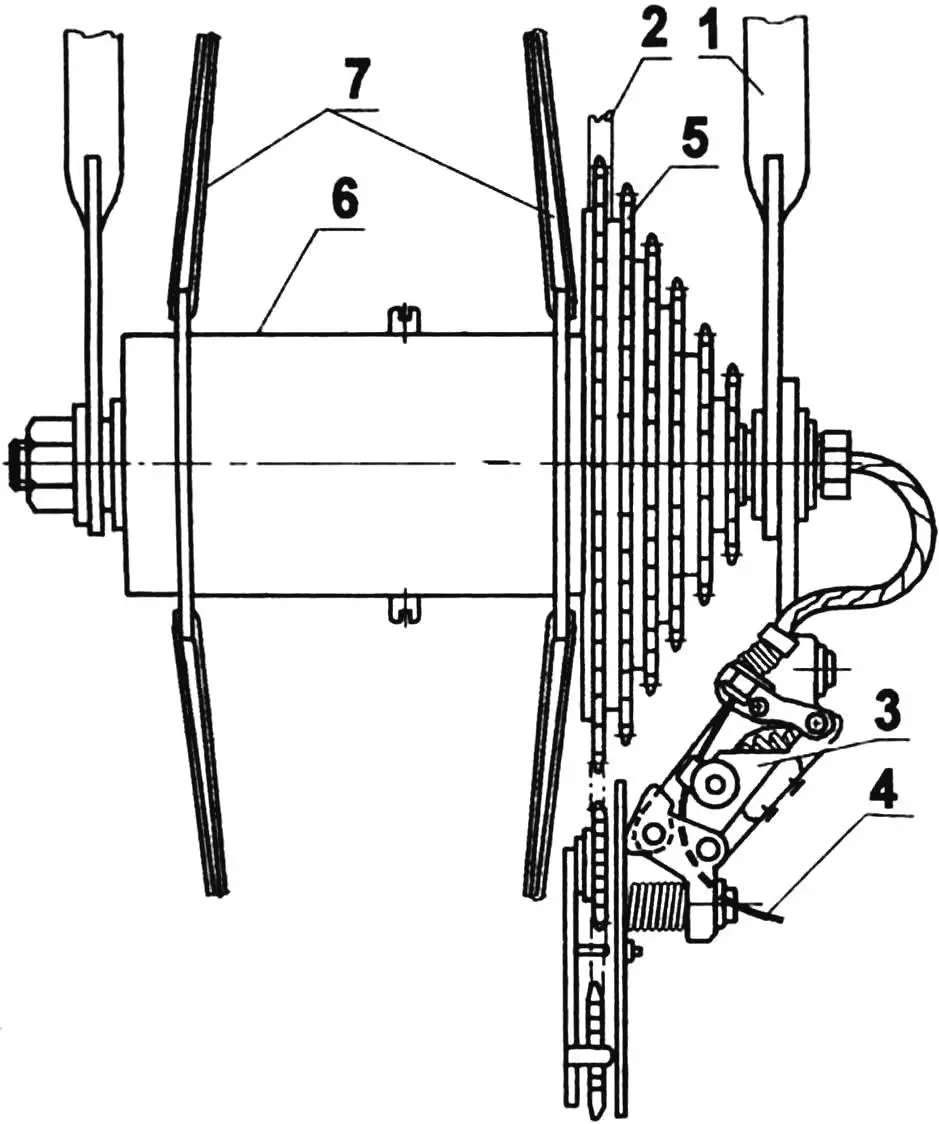
1 — rear bicycle fork; 2 — chain drive (chain t = 12.7); 3 — gear shifting carriage (standard); 4 — cable; 5 — sprocket block; 6 — automatic gear shifting hub; 7 — rear drive wheel spokes
In terms of overall and mounting dimensions, the developed hub is approximately the same as the hubs of road bicycles with a foot brake, so it can be inserted into a standard wheel without problems. But the manual gear shifting drive (long cables, levers and shifters) can be thrown away as unnecessary. At the same time, the bicycle will not only become slightly lighter, but will also turn into an automatic bicycle without excessive energy loss. Gear shifting occurs automatically, but classically — by throwing the chain from sprocket to sprocket. The hub itself controls the throwing. The cyclist’s task in this case is only to pedal at an acceptable and convenient frequency.
The entire automatic gear shifting mechanism (changing the torque) is located in the hub housing on the stationary axis of the drive rear wheel. Conventionally, the mechanism can be divided into several links: input, control, regulating, actuating and switching, although the latter is already outside the hub. We have to note the conventionality of the division because it is still an integral mechanism and the boundary parts of adjacent links can rightfully be attributed to both the previous and the next link.
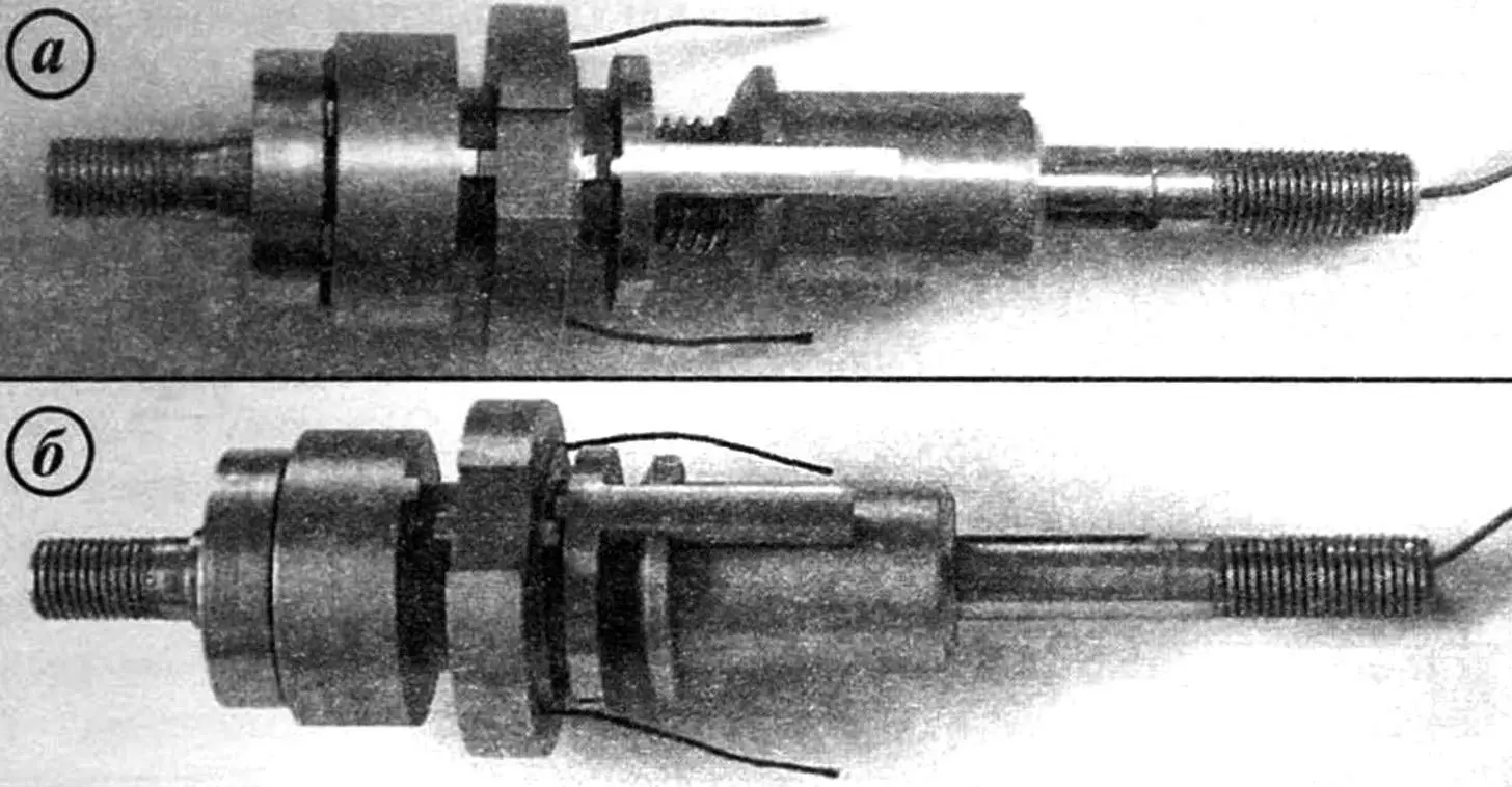
a — ring is in neutral position; b — ring is engaged with threaded half-coupling
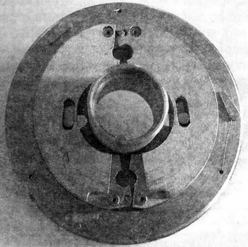
The input link consists of hub 39, four semi-annular weights 20, 21, 22, 23, two flexible rods 11 (connecting the weights with the control ring 6), normally released return spring 8 and cup 10, against which the spring rests, and also a key. The key is composite: it contains an elastic part — rubber 3 and a rigid part — steel 5. The key is fixed on the hub housing 2 with two rivets 4.
The weights can be conditionally subdivided into pairs: driving 20, 21 and driven 22, 23. Each of the weights is suspended on its own axis 36. The axes are pressed into hub 39 from diametrically opposite sides from the center, two pieces each. At the same time, the driven and driving weights (also in pairs) are united by pin 40, each of which is also pressed into the hole of the driving weight. An oval slot is made in the driven weight for the pin. Rotating together with hub 2 and hub 39, the weights move apart under the action of centrifugal force or move together again under the action of return spring 8 when the wheel rotation speed decreases.
The control link consists of control ring 6 with a slot for the key and two half-couplings: threaded 7 and reverse 48 with satellites 49. The threaded half-coupling in its right part (from the side of the sprocket block) has the shape of a two-pronged fork, and the left part is cylindrical. In this part, the half-coupling has an internal left thread M12x0.5 and is screwed onto a section of the axis with the same external thread.
The reverse half-coupling 48 is made in the form of a two-stage cylinder. The right part of the half-coupling is mounted on the threaded half-coupling freely, and the left one — through two satellites. For this, corresponding teeth with module m = 0.5 mm are cut on both half-couplings: on the threaded one — on the outside, and on the reverse one — on the inside. The satellites provide the possibility of reverse rotation of the reverse half-coupling relative to the threaded one, which makes it possible to shift from a higher speed to a lower one. The control link ensures sequential gear shifting both from lowest to highest and back, as well as clear operation of the mechanism.
The actuating link consists of threaded bushing 44, pressed onto a section of axis 25 with a diameter of 10 mm, nut 45 and sleeve 43 mounted on it with tension along a diameter of 20 mm (during hub assembly).
The bushing and nut have thread Tr16x6(P2)L — trapezoidal left three-start with a pitch of 2 mm, only the bushing has an external thread, and the nut has an internal thread. At the same time, the actuating link has a constant movable connection with the control link through the fork of the threaded half-coupling 7, which enters the slots of the sleeve rim.
The switching link consists of cable 28 and a standard multi-speed bicycle carriage. The cable is connected to the sleeve of the actuating link by means of bar 41 and clevis 42 with a locking ring. The bar moves in the axis slot, while sleeve 43 slides along its surface.
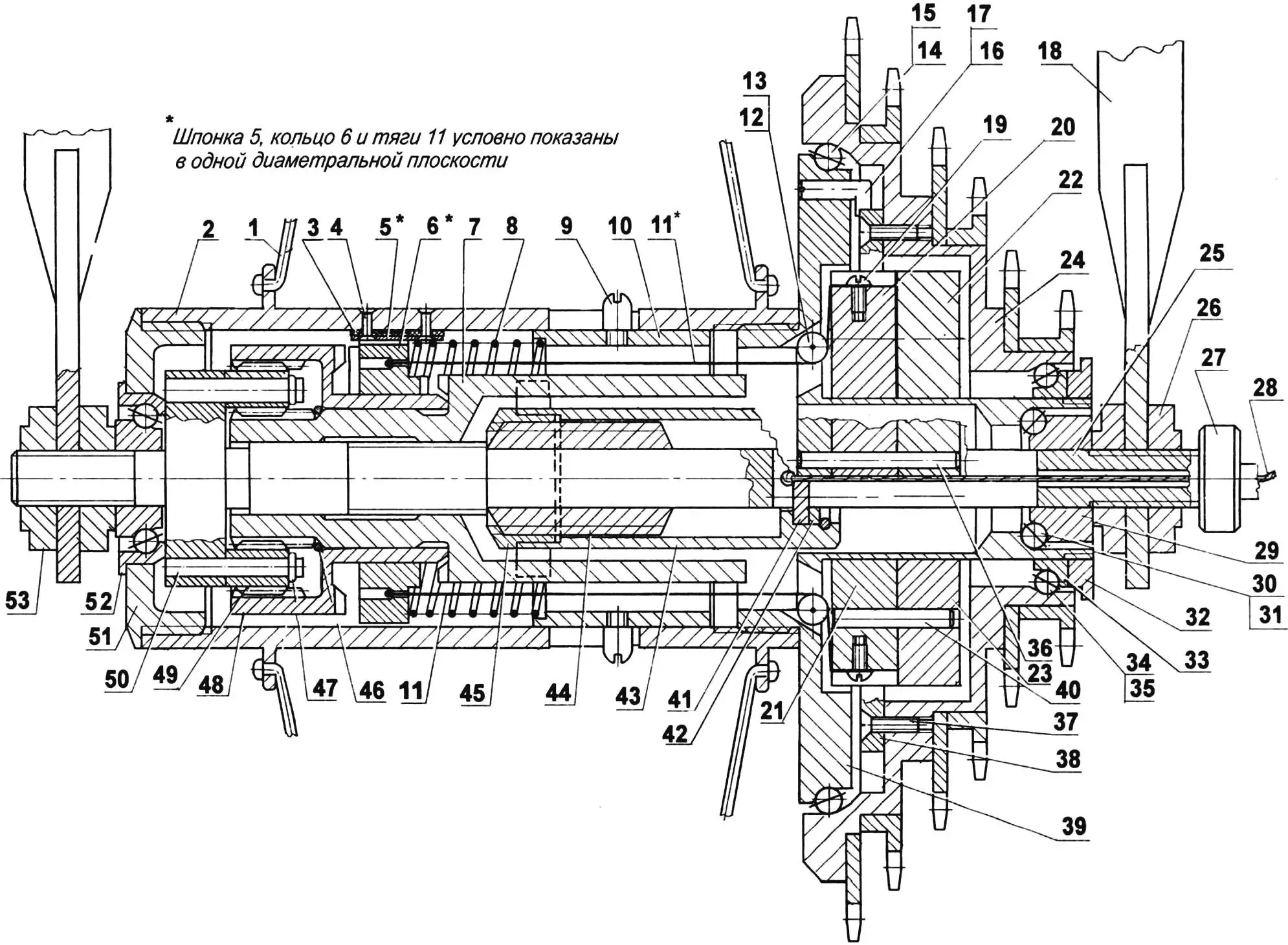
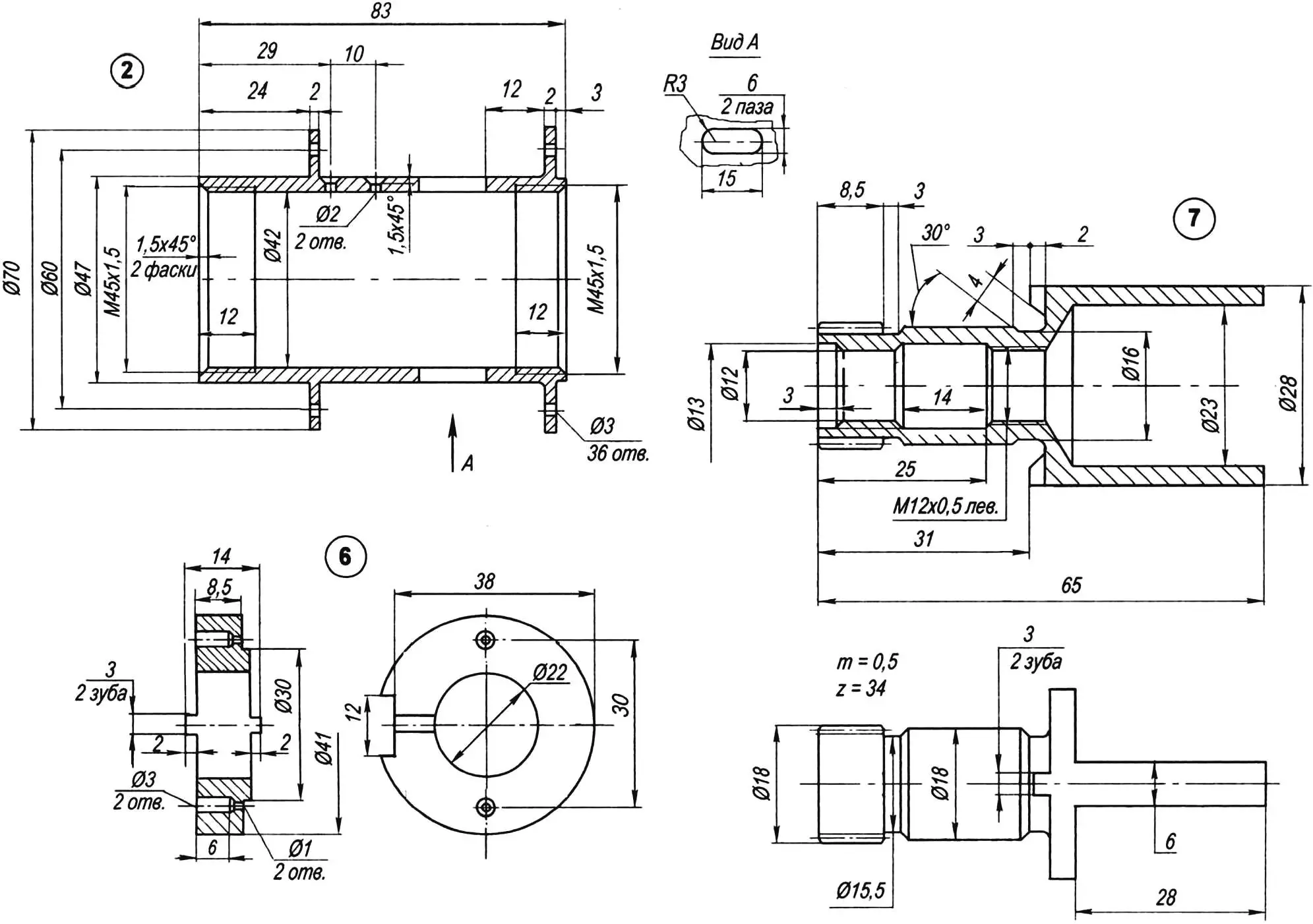
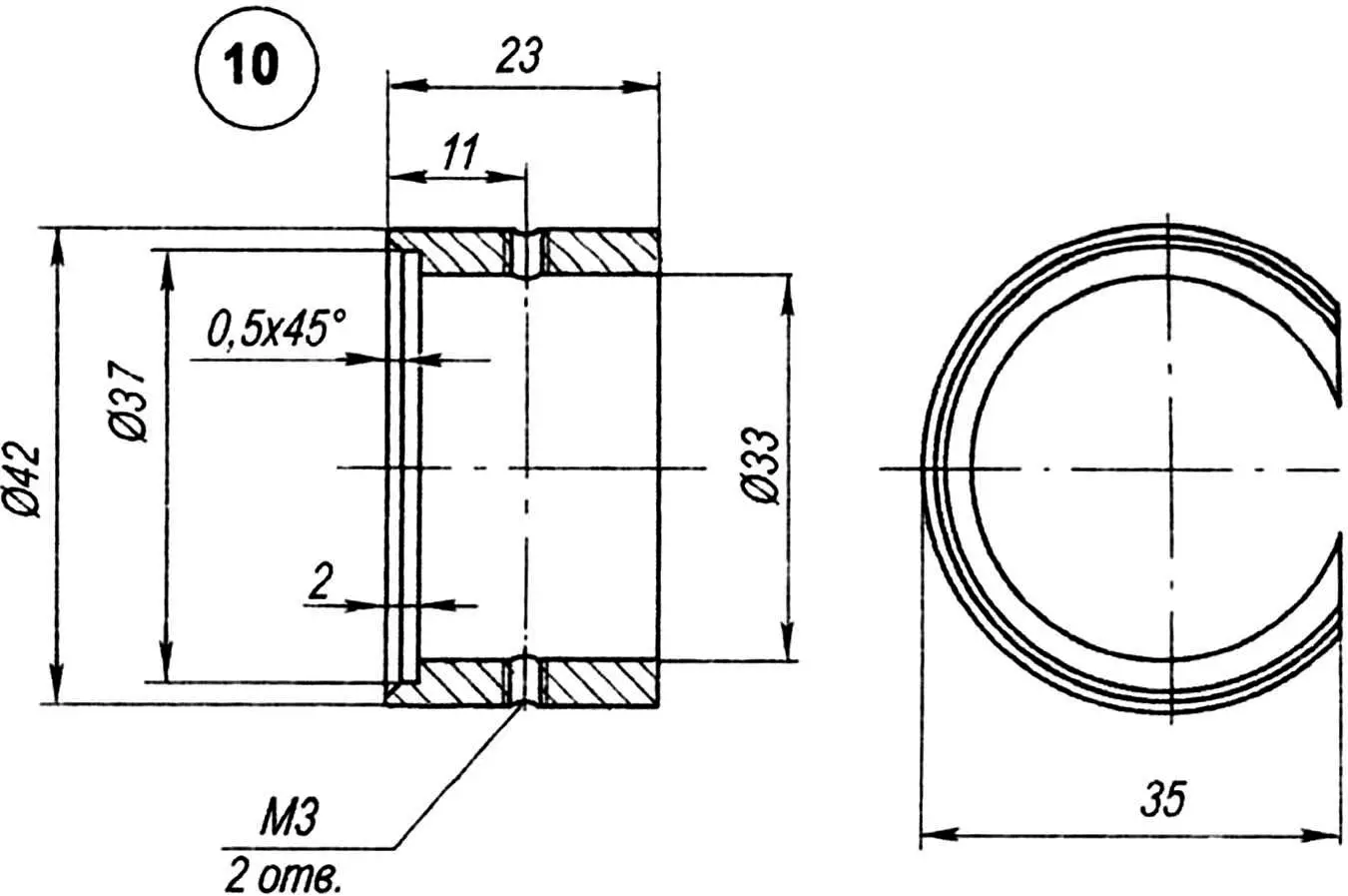
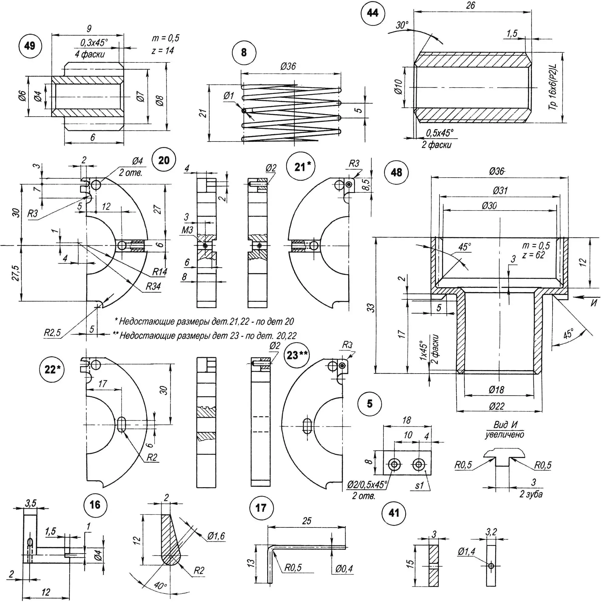
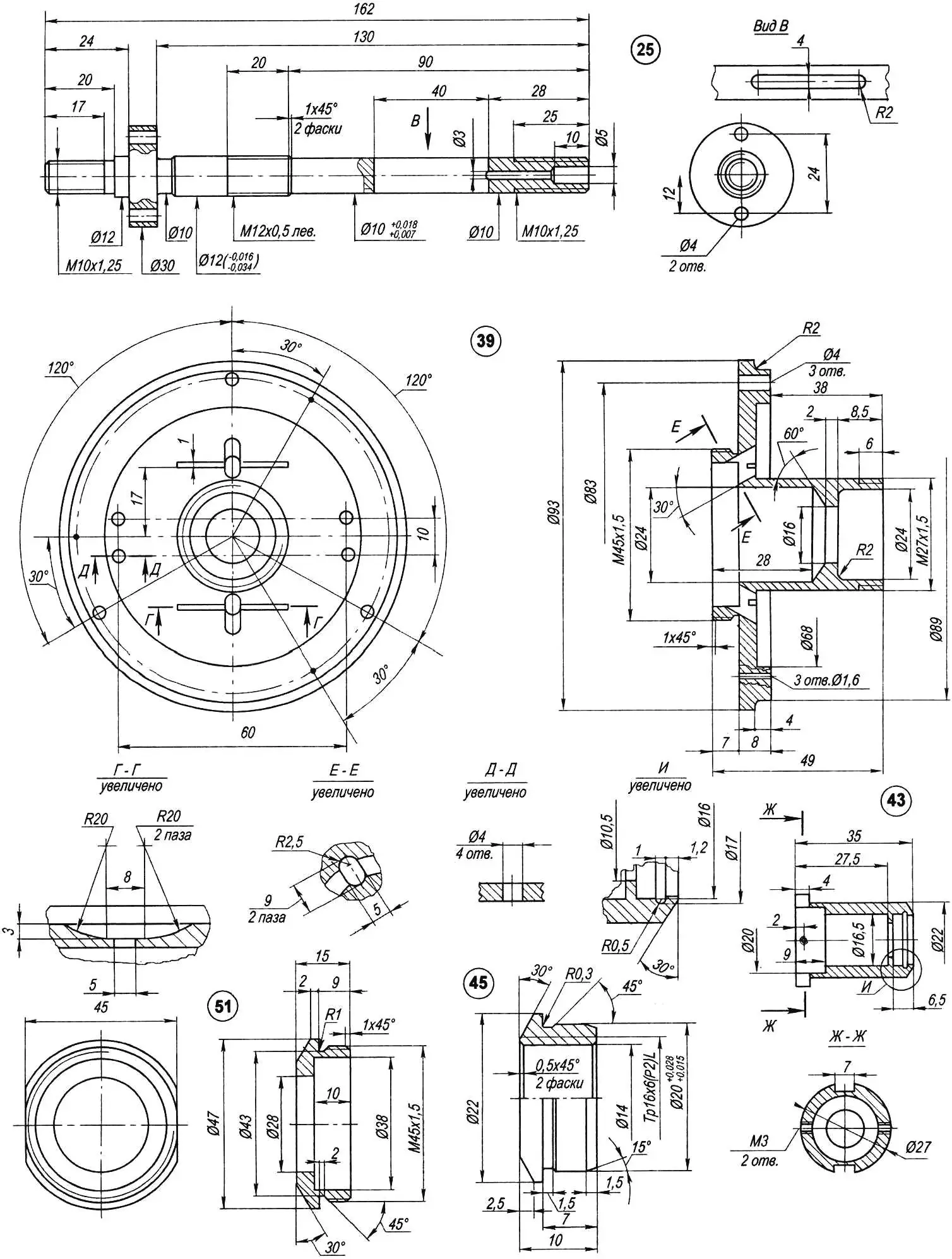
1 — wheel spoke (36 pcs.); 2 — hub housing (steel 45); 3 — elastic part of key (rubber); 4 — rivet (St3, Ø2, L5, 2 pcs.); 5 — key (steel 45, sheet s1); 6 — control ring (steel 45); 7 — threaded half-coupling z = 34, m = 0.5 (steel 45); 8 — spring (wire Ø1); 9 — pin with M3 thread of cup (steel 45, 2 pcs); 10 — cup (St3); 11 — rod (cord thread Ø1, 2 pcs); 12 — block (St3, 2 pcs); 13 — block axis (wire Ø1, 2 pcs); 14 — large bearing ball Ø4 (12 pcs); 15 — large bearing separator (St3); 16 — pawl (steel 40Х, 3 pcs); 17 — pawl spring (wire Ø0.4, 3 pcs); 18 — bicycle fork blade; 19 — rod fastening on weight (screw M2х4, 2 pcs); 20 — driving weight with slot (steel 45); 21 — driving weight with boss (steel 45); 22 — driven weight with slot (steel 45); 23 — driven weight with boss (steel 45); 24 — hub with sprocket block; 25 — rear wheel axis (steel 45); 26 — nut M10х1.25 (steel 40Х, 2 pcs); 27 — cable sheath fastening nut M10х1.25 (steel 40Х, knurled surface); 28 — cable Ø2.5 in Bowden sheath; 29 — small bearing inner cone (ShKh15, 2 pcs); 30 — small bearing ball (8×2 pcs); 31 — small bearing separator (St3, 2 pcs); 32 — medium bearing inner cone tightening nut (steel 45, round 35); 33 — medium bearing inner cone (ShKh15, round 34); 34 — medium bearing ball Ø4 (8 pcs.); 35 — medium bearing separator (St3, round 38.5); 36 — weight rotation axis (steel 40Х, 4 pcs); 37 — M3 screw for fastening ratchet to sprocket block hub (12 pcs); 38 — ratchet (steel 45, round 80); 39 — hub (steel 45); 40 — pin (steel 40Х, round 4, 2 pcs); 41 — bar (steel 45); 42 — clevis (St3, round 16) with locking ring (wire Ø1); 43 — actuating link sleeve (steel 45); 44 — actuating link threaded bushing Trl6x6(p2)L (steel 45); 45 — actuating link nut Trl6x6(p2)L (steel 45); 46 — reverse half-coupling thrust ring; 47 — satellite thrust ring; 48 — reverse half-coupling z = 62, m = 0.5 (steel 45); 49 — satellite z = 14, m = 0.5 (steel 45); 50 — satellite axis (steel 45, Ø4, 2 pcs); 51 — hub cover (steel 45, round 60); 52 — small bearing outer cone; 53 — nut M10х1.25, left (steel 40Х, round 25, 2 pcs.)
The carriage throws the drive chain as on a regular multi-speed bicycle, but only strictly sequentially from one sprocket to the adjacent one.
At the start of movement, the hub elements converge in the position shown in figure 2. The chain is thrown on the largest sprocket, and there are small gaps (about 0.5 mm) between the teeth of control ring 6, threaded half-coupling 7 and reverse half-coupling 48.
With the start of movement, hub housing 2, and together with it hub 39 and weights 20 — 23 begin to rotate together with the wheel. Housing 2 through key 5 forces control ring 6 to rotate as well.
With increasing speed, under the action of centrifugal force, weights 20 — 23 begin to move apart and through rods 11 act on control ring 6, forcing it to move to the right (towards the sprocket block). At the same time, the gap between the teeth of control ring 6 and threaded half-coupling 7 is taken up, the teeth engage (literally by 0.5 mm) and threaded half-coupling 7 rotates one turn and moves one thread turn (pitch 0.5 mm) along axis 25. The control ring itself at this time rests with the wall of the slot against the elastic rubber part 3 of the key (fig.3b) and, due to friction against it, stops moving along the axis. The teeth of ring 6 and half-coupling 7 after its rotation by one turn disengage, stopping the rotation of the threaded half-coupling (this happens at the end of the gear shifting cycle).
During the contact time of the teeth, half-coupling 7 through its fork, inserted into the slots of sleeve 43, forces it together with the nut 45 pressed into it to also rotate one turn. At the same time, the actuating link moves along the axis to the right along the trapezoidal thread by one stroke (for a three-start thread — by 3 steps, that is, by 6 mm).
At this moment, the tensioned cable 28 acts on the gear shifting mechanism (it is standard and not shown in the figure), which, in turn, throws the chain onto the adjacent (smaller) sprocket. With further increase in speed, the cycles repeat until the chain is on the smallest sprocket — at this time the cyclist will move at maximum speed.
When the speed decreases, the weights will begin to converge, the rods will weaken, and control ring 6 under the action of spring 8 will begin to shift to the left until it engages with reverse half-coupling 48, forcing it to rotate. At the same time, the reverse half-coupling will rotate threaded half-coupling 7 (but already in the opposite direction than during acceleration), which, in turn, will force sleeve 43 with nut 45 to also rotate in the opposite direction and move to the left. The latter parts will pull the cable behind them through bar 41 and force the shifting mechanism to throw the chain onto a larger sprocket. At this time, the cyclist can overcome climbs without increasing the effort on the pedals and the speed of their rotation. The cycles of shifting to lower speeds will repeat until the bicycle stops.
Each gear shift occurs in a strict sequence, which is explained by the graphic material presented in figure 3.
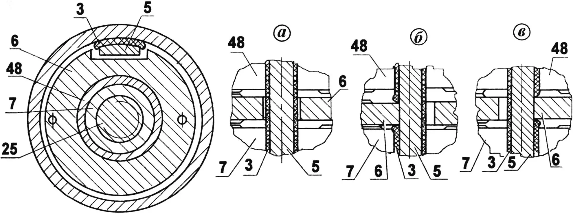
a — neutral position (teeth of control ring 6 and half-couplings 7 and 48 are not engaged and have a gap); b — tooth of control ring 6 is engaged with tooth of threaded half-coupling 7 — shifting to higher speed occurs; c — tooth of control ring 6 is engaged with tooth of reverse half-coupling 48 — shifting to lower speed occurs
In conclusion, several recommendations on manufacturing and assembly technology.
Blanks of parts made of steel 45 should be subjected to improvement (hardening and tempering) to 35—42 HRC.
During mechanism assembly, the rubbing surfaces of parts must be lubricated with grease.
The position of cup 10 (and therefore, the preliminary spring tension) of the input link is adjusted before the trip using pins 9 depending on the physical capabilities of the cyclist. To do this, you need to press both pins simultaneously with your fingers and move the cup to the desired position. When the pins are released, the cup again self-locks in the hub housing. If the cyclist is young and full of strength, the cup is shifted further from the sprocket block, and vice versa.
V. ALESHIN, design engineer
Recommend to read
 GLUE AND IRON
In improvised furniture experience the greatest difficulties when sealing the ends, especially chipboard. I hang the ends of the veneer. On cut to size a strip of veneer put in a thin... IT WAS CREATED TO FIGHT
He was born in the terrible days of August, forty-one. It was created for combat and was ready to fight. Fast, agile, and with powerful small arms and rocket weapons, finally, sheltered...
