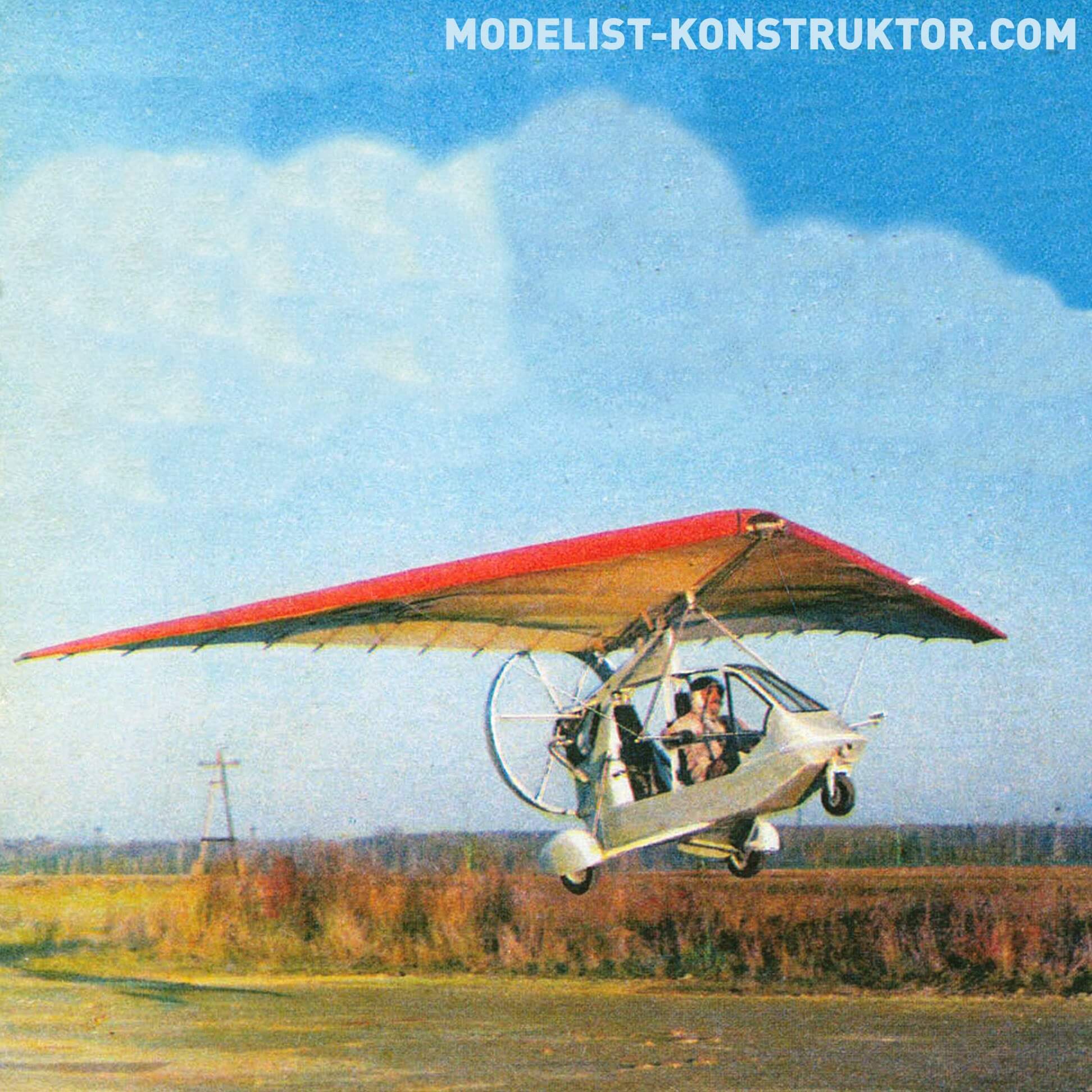
This small aircraft attracted attention at the Tushino International Salon in June 1995. It differed from other similar ones in its somewhat unusual layout. In a conversation with its creators, it turned out that such a design decision was made as a result of deep theoretical and experimental work carried out by the authors in the field of aerodynamic interaction of the wing and propeller of trikes. We asked one of the designers of the Comet project and pilot S. Sitdikov to tell us more about our brainchild.
The history of the creation of the Comet hang-glider dates back to the late 70s, when a group of enthusiasts – employees of the Scientific Research Laboratory and students of the VVIA named after. N.E. Zhukovsky – decided to devote her free time to researching the aerodynamics of a hang glider wing, which at that time was experiencing rapid development in the vastness of the former USSR. At the same time, design work was carried out. By the time the first hang glider was created in a wind tunnel, the aerodynamic characteristics of the soft wing profiles had already been obtained, the effectiveness of the anti-dive device had been studied on an elastic model, and the distribution of the air load on the wing, necessary for calculating the strength of the structure, had been calculated using a computer.
Our first trike AKS-1M (V.Aparinov, A.Karask, S.Sitdikov) was created in 1983 as part of my diploma work. It was intended to receive express information about the ground situation in the vicinity of specified objects. The basic ideas implemented in this design were further developed on all subsequent machines. This is primarily a wing made without upper braces; anti-dive device located at the end parts of the wing; a propeller enclosed in an aerodynamic ring.
In the course of further work on the creation of delta planes, such as KS-2 (1987, single-seat) and “Kometa” (1993, double-seat), the team of authors – A. Karask, S. Sitdikov, Yu. Shchegolev – developed a new aerodynamic layout, which organically includes all the above elements. This made it possible to significantly improve their flight performance and operational characteristics.
One of the main tasks was to find ways to increase cruising and maximum flight speed while maintaining a constant specific wing load. After all, modern trikes do not have take-off and landing mechanization (and its implementation today is problematic). Therefore, an increase in cruising flight speed will inevitably cause an increase in the specific wing load. And the increase in maximum flight speed due to increased power supply is limited by the minimum permissible angle of attack.
To meet these conflicting requirements, research into the aerodynamics of trike aircraft has been conducted to identify opportunities for improving the load-bearing properties of the wing. It turned out that this can be achieved, for example, by implementing the conditions of positive interference between the wing and the pusher propeller jet (on modern designs, negative interference is realized, since the propeller is located under the wing).
Based on this, the design features of our “Comet” developed: a relatively low location of the wing in relation to the screen (earth or water surface); extension of the propeller plane beyond the trailing edge of the wing in such a way as to ensure the position of its axis as high as possible above the level of the trailing edge during takeoff and landing conditions; the passage of the propeller thrust vector in the immediate vicinity of the suspension point of the motorized cart to the wing.
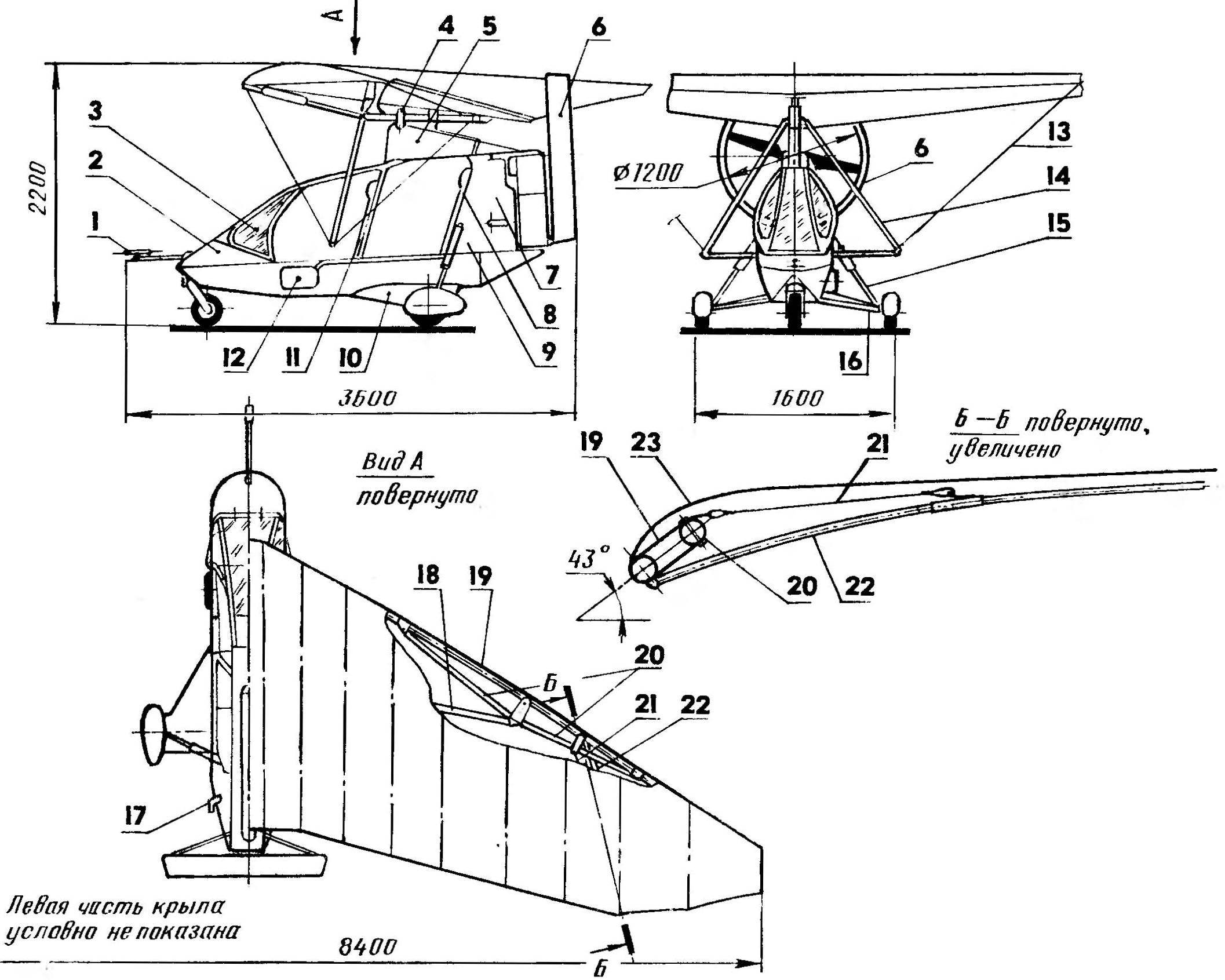
Delta plane “Comet”:
1 — Venturri tube, 2 — canopy, 3 — canopy glazing, 4 — suspension unit of the motorized trolley to the wing, 5 — pylon, 6 — ring attachment, 7 — engine compartment, 8 — passenger seat, 9 — luggage compartment, 10 — fairing of the lower landing gear strut, 11 — pilot’s seat, 12 — parachute capsule, 13 — lower brace, 14 — steering linkage, 15 — upper landing gear strut, 16 — lower landing gear strut, 17 — exhaust pipe, 18 — spar, 19 — side beam , 20 — side beam struts, 21 — anti-dive device cable brace, 22 — anti-dive device beam, 23 — wing skin.
The approach of the wing to the screen led to an increase in lift force and aerodynamic quality during takeoff and landing modes by 10 and 20%, respectively (compared to the conventional layout).
Moving the plane of the propeller beyond the trailing edge contributed to the elimination of negative interference and the creation of positive interference between the propeller and the wing, which ensured an increase in the lift of the wing up to 10-15% of its original value.
Anyone who has flown or is flying on trikes knows such an unpleasant phenomenon as the “pumping” of a motorized cart suspended under the wing relative to the steering linkage under the influence of the thrust force of the propeller-engine unit (PMU). Moreover, the greater the leverage and the amount of thrust relative to the suspension point, the greater the amount of “pumping”.
On the first cars, equipped with relatively low-power engines, the effects of “pumping” were practically not felt. However, today the engine power sometimes reaches 80 hp. This, with the classic configuration of the trike, leads to “pumping” up to 0.8-1 m, which is much more than we can fend off with our hands (0.5-0.6 m). As a result, handling characteristics sharply deteriorate and the requirements for pilot qualifications increase.
And the passage of the propeller thrust vector in the immediate vicinity of the suspension point of the motorized trolley practically eliminates the moment from the thrust force of the VMU.
These are the main fundamental decisions. Now about the main design features of the wing. It does not have an upper mast with braces; the design of the side beams is truss; and anti-dive devices are located in the console parts.
Due to the absence of an upper mast with braces, negative loads are absorbed by the spar (it is box-section, riveted). Design operational overload n e = -2, safety factor for all design cases £ = 1.5 (where £ is equal to the ratio of the destructive load to the maximum operational load), which guarantees the safety of the aircraft in the event of its accidental departure from permissible flight conditions. Positive loads, as on a conventional wing, are absorbed by cable braces, and the spar in this case acts as a cross member. Design operational overload n ue =4. The side beams of the wing are supported by struts (the mounting plane of which is rotated at an angle of 43 degrees with respect to the horizontal plane), ensuring the passage of the vector of resulting forces along the axis of the maximum moment of inertia of the wing section. This design of beams reduces their weight and simplifies the manufacturing technology.
The anti-dive device consists of a tubular beam (diameter 20×1.5 mm), hinged on the side beam, and a cable brace connected at one end to the strut, and the other to the anti-dive device beam. This provides a given wing twist angle and the required value of the longitudinal moment coefficient > O.
The relative thickness of the wing profile (c = 8%) is constant along the span, which is maintained in flight by connecting the upper patch pockets to the lower ones with nylon tape.
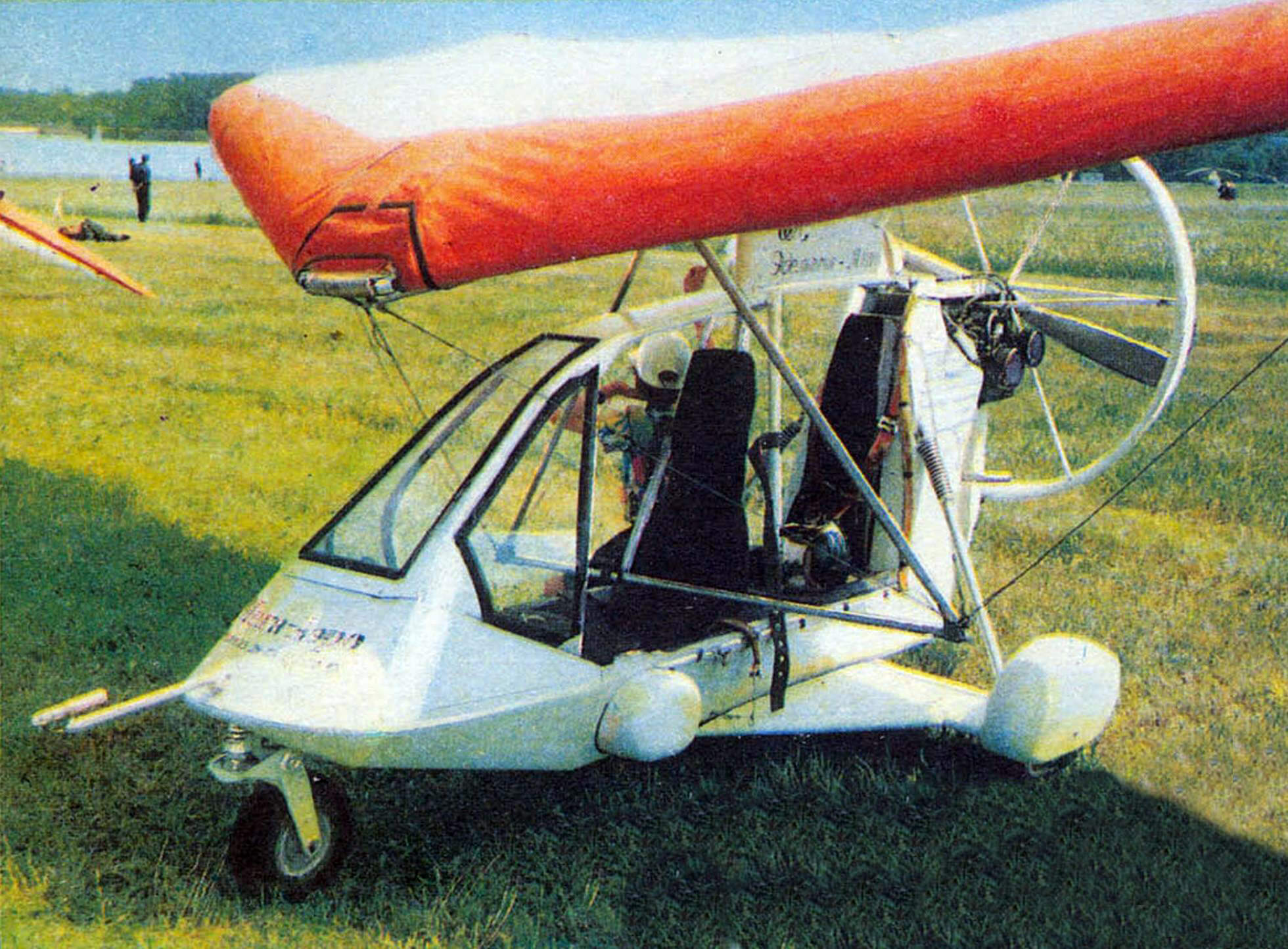
The motorized trolley consists of a body, a propeller-motor unit, a chassis and a rescue system.
The body, or rather the fuselage, is of riveted semi-monocoque construction. It has a two-seat semi-enclosed cabin in which the pilot and passenger are seated in tandem. Behind the back of the passenger seat there are luggage and equipment compartments, combined with the engine compartment. The “working” skin is made of duralumin sheets 1.5 mm thick.
MAIN TECHNICAL CHARACTERISTICS OF THE “COMET” FLIGHT FLIGHT
Maximum take-off weight, kg…………. 360
Dry weight, kg……………………………………. 180
Number of seats…………………………………2
Engine power, l. With…………………. …..37
Fuel tank capacity, l…………………… 20
Swing, mm………………………………………………………8400
Length, mm ……………………………………………………… 3600
Height, mm…………………………………………. 2200
Wing area, sq. m……………………………12.5
Wing extension…………………………………. 5.65
Run/mileage, m…………………………….. 70
Rate of climb, m/s……………………….. 2
Maximum speed, kt^ …………………. 120
Cruising speed, kt^……………………… 100
Flight range, km……………………………. 200
Wing dimensions when folded, m……4.8×0.5×0.3
The removable canopy is pivotally connected to the fuselage pylon. Its front part is raised when the wing is mounted to allow the steering linkage to pass into its working position. The glazing is curved from flat sheets of plexiglass 2 mm thick and is sealed into the load-bearing frame through a rubber seal. The frames of the pilot’s and passenger’s seats are structurally included in the power structure of the fuselage and are made taking into account the requirements of passive safety rules.
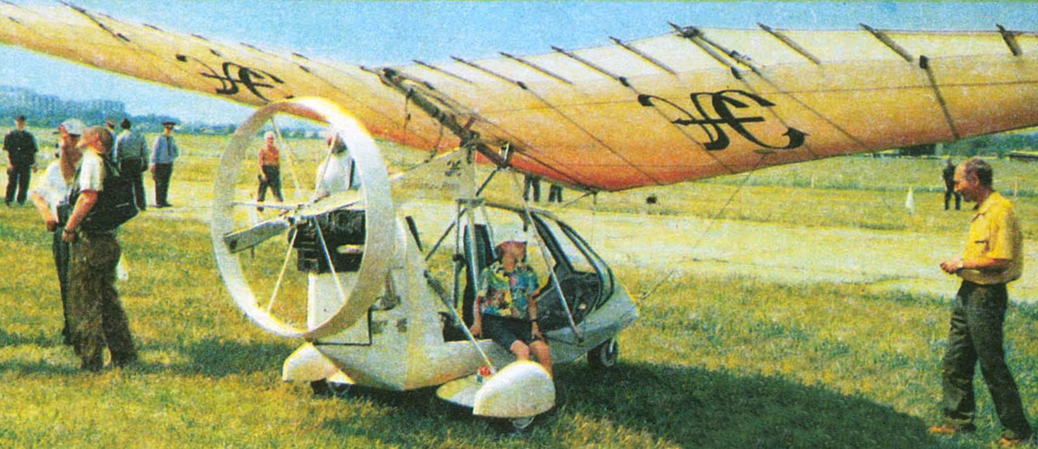
The propeller installation includes an engine, a propeller and a ring nozzle.
The RMZ-640A engine has an internal gear reducer with a gear ratio of 1:1.6. A two-blade wooden propeller with a diameter of 1200 mm (with the ability to change the pitch on the ground) is enclosed in a ring nozzle, which also serves as a tail unit. It ensures increased efficiency of the propeller, reduced noise, safety of operating personnel and surrounding people, and protects the propeller from damage in emergency situations.
Three-wheel landing gear – with a nose strut. All landing gear struts are shock-absorbed. The load on the front strut is 10% of the total, which makes it possible to lift off the front wheel earlier and, accordingly, have a shorter takeoff run. The main landing gear is of a pyramidal type. Their lower struts are equipped with fairings, which together with the ventral part form an additional load-bearing surface with an area of 1.5 sq.m.
The wheels of the main landing gear are from the Riga Mokik (400×100 mm) and are equipped with the same shoe-type brakes, with a foot drive. The front wheel is from a go-kart, not braked (300×150 mm).
The parachute capsule of the MVEN “Cobra” rescue system is installed under the pilot’s seat. The parachute halyard runs along the structural elements of the fuselage and wing and is attached to the pylon of the motorized vehicle.
The instrumentation includes a magnetic compass type KI-13; altimeter VD-10; variometer VAR-10; speed indicator of the US-250 type, recalibrated to a scale of up to 120 km/h and working in conjunction with a Venturri tube, boat-type tachometer; two-pointer cylinder head temperature indicator.
In conclusion, I would like to emphasize that our design can not only fly well, but also, if necessary, turns into a ground vehicle: on wheels it is an airmobile, on skis it is an snowmobile. Naturally, the wing is removed, folded into a compact package, secured along the borg, or remains at its location.
S. SITDIKOV, Candidate of Technical Sciences
Recommend to read
 A COLOR FOR EVERY TASTE
Comfort in our home is not only matching Wallpaper and curtains upholstery and carpet, but the shape of rooms, their purpose, and the lighting and color harmony. 1. Furnished. It... “MOSQUITO” WITH FEATHERS
Among purchase toys that can move (ride, swim, run, fly, crawl), it is not easy to find such models that can be safely run in the apartment without fear that they'll break, dropping to...
