Most of the vehicles I built were based on mass-produced noisy and “fuel-guzzling” motorcycle or bicycle internal combustion engines. This was convenient on one hand, but very troublesome on the other, as the quality of the engines rarely satisfied and I had to spend a lot of effort, and most importantly, time on their refinement and tuning. That’s why the idea of using an electric drive as a power unit always appealed to me. Understanding that there are pros and cons here too, and primarily difficulties with the power source, I always left the electric bike version “for later.” However, first the absence, and then the high cost of gasoline forced me to turn to it again.
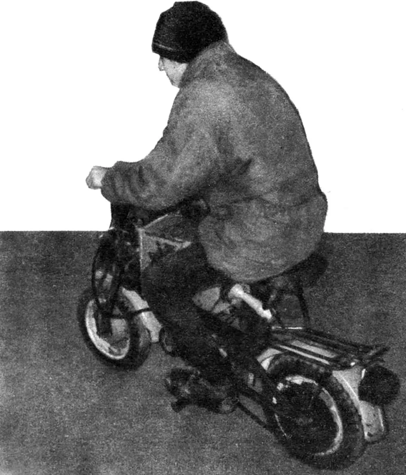
The basis of the design was the frame and chassis of a Riga mini-moped. As the engine, I used an electric MN-1 series-wound motor with a good combination of power (1.5 kW, 24 V) and dimensions. Unfortunately, the issue of a light but capacious battery remained unresolved, so I had to take a large heavy automotive one for this purpose, place it in a metal box-compartment and secure it on the frame instead of the fuel tank. I understand: such a “thing” doesn’t beautify the machine, but there was no other way out.
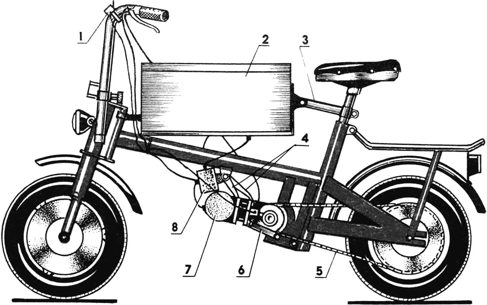
1 — motor switch, 2 — battery compartment, 3 — battery compartment mounting rod, 4 — upper power unit mounting rods, 5 — rear wheel drive chain, 6 — lower power unit mounting rod, 7 — power unit, 8 — control equipment box.
To reduce the revolutions transmitted from the engine to the drive wheel, I used a modified gearbox from a “Universal” electric drill. I must say that mainly its housing was modified: on the high-speed shaft side, the shaft itself was replaced and a hole was bored for the outer bearing sleeve 201, and on the opposite side — surfaces were prepared for installing the locking wheel, bearing 1000109, and on the end rim of the wheel, corresponding cams were cut for engagement with the drive gear. The kinematics, however, remained practically unchanged, including the low-speed shaft with a hexagonal shank.
The use of a double bearing unit is due to the change in direction and magnitude of the acting forces when the gearbox operates under different conditions compared to the drill.
The locking wheel is made of steel sheet and fixed to the housing with three M3 screws. The teeth on it are cut using a grinding wheel, and the distance between them (or pitch) is not of great importance, as the position of the housing relative to the supports can be any. The supports themselves were not specially manufactured, but were selected from those found in “scrap” (as we call metal scrap in factory yards, intended for remelting) and bored to fit the corresponding bearings.
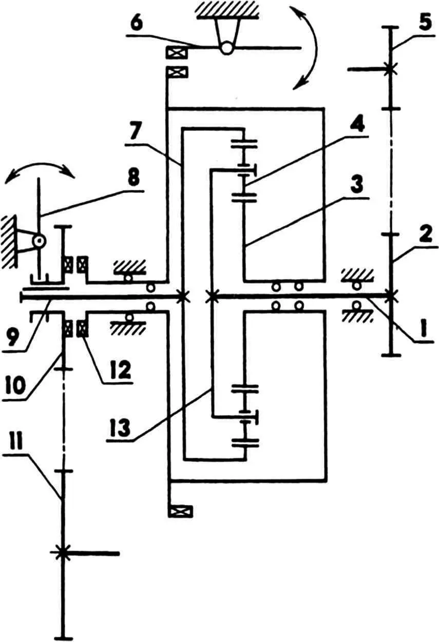
1 — gearbox high-speed shaft, 2 — intermediate gear (z=14), 3 — gearbox housing sun gear, 4 — satellite, 5 — engine gear (z=10), 6 — locking mechanism, 7 — ring gear, 8 — speed switching mechanism, 9 — gearbox low-speed shaft, 10 — drive half-coupling gear (z=15), 11 — rear wheel gear (z=55), 12 — half-coupling, 13 — carrier.
The gearbox, modified in this way and installed in bearing supports, allows it to be used in a two-speed version. First speed mode — housing is locked, coupling is disengaged, rotation from the high-speed shaft through the carrier and satellites is transmitted to the ring gear, whose shaft (low-speed) drives the drive half-coupling gear. In this case, a gear ratio of 4:1 is provided. Second speed mode — housing is released, coupling is engaged, the gearbox rotates as a single unit, speed ratio — 1:1.
The gearbox supports and the engine with base are secured to the platform with M8 bolts. The latter — through a bracket and spacer sleeves, with which the drive chain tension is adjusted.
Housing braking is performed by a lock made in the form of a spring-loaded pawl, pulled to the platform with a bolt.
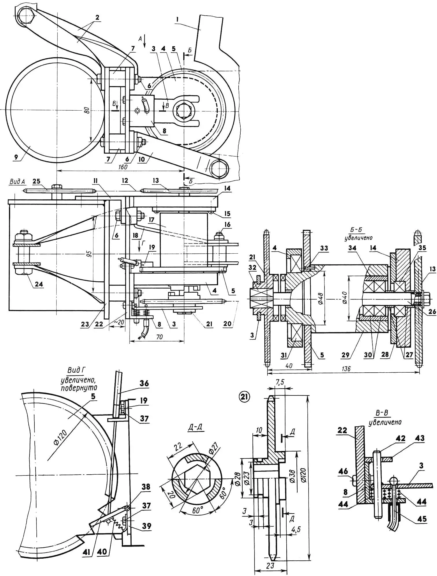
1 — frame brackets, 2 — upper rods (St3, strip 4×24), 3 — speed switching mechanism fork (steel 45, sheet s3), 4 — left gearbox support (D16T), 5 — locking gear wheel (St3, sheet s6), 6 — M8 bolt, 7 — spacer sleeves (D16T, tube 20×3), 8 — speed switching mechanism bracket (St3, angle 30x30x3, L40), 9 — electric motor, 10 — lower left rod (St3, strip 4×24), 11 — electric motor mounting bracket (St3, s5), 12 — gearbox drive chain, 13 — intermediate gear, 14 — right gearbox support (D16T), 15 — M4 screw, 16 — M6 bolt, 17 — gearbox from “Universal” electric drill, 18 — lower right rod (St3, strip 24×4), 19 — locking mechanism bracket (St3, angle 15×15, L15), 20 — rear wheel drive chain, 21 — drive half-coupling gear (steel 45), 22 — gearbox platform (D16T, sheet s6), 23 — electric motor base (St3, sheet s5), 24 — M10 bolt, 25 — engine gear, 26 — gearbox input high-speed shaft (shortened, from “Verkhovina” moped), 27 — limiting sleeves (bronze), 28 — bearing cover (D16T), 29 — gearbox housing, 30 — intermediate bearings 201, 31 — left bearing 9000109, 32 — gearbox output low-speed shaft, 33 — M3 screw, 34 — outer bearing sleeve (steel 45), 35 — right bearing 201, 36 — locking mechanism drive cable sheath, 37 — M5 bolts, 38 — hinge, 39 — loop (St3, sheet s2), 40 — tension spring, 41 — pawl (St3, sheet s3), 42 — guide pin (steel 45, rod Ø6), 43 — cheek (St3, sheet s3), 44 — compression springs, 45 — speed switch drive cable, 46 — M5 bolt (2 pcs.).
The homemade drive half-coupling gear can freely slide along the hexagonal shank of the low-speed shaft. Its position and fixation are determined by the position of the speed switching mechanism fork, which, besides it, also consists of a bracket, guide pin, and return springs. The last two serve to prevent fork misalignment.
Control of both the locking mechanism and speed switching is cable-operated and routed to the mini-moped handlebar, and the entire power unit is suspended from the frame using upper and lower pairs of rods.
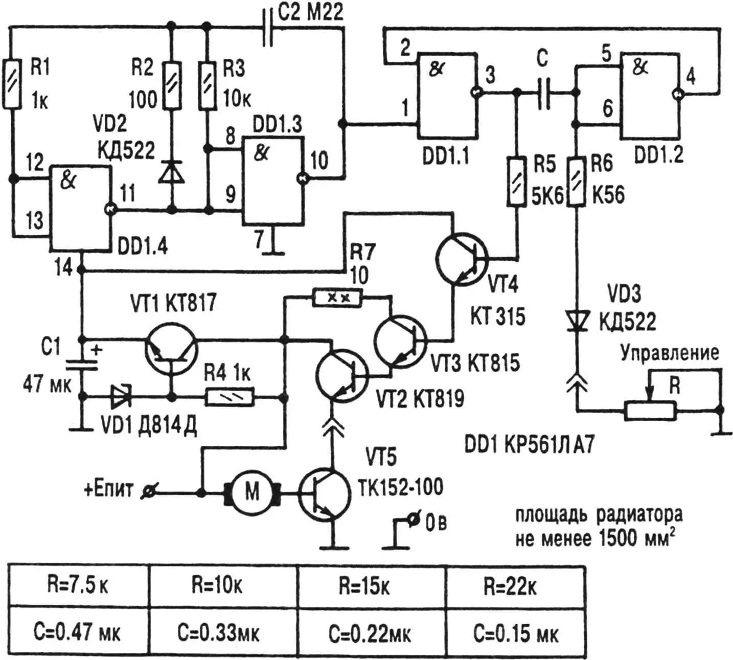
The electric motor control equipment is housed in a metal box and suspended under the moped frame. The side walls of the box are perforated to cool the power elements of the electrical circuit that heat up during operation.
Road tests of the machine and its operation over two seasons have shown that such designs have a right to exist. The electric bike starts smoothly and reaches speeds of up to 30…35 km/h, climbs hills without much difficulty and rolls down them briskly. The battery capacity is sufficient for more than three hours of travel. After which, of course, it has to be recharged, and this operation is not pleasant, as the battery is quite heavy, and I advise those who want to repeat our experiment to find a lighter power source.
V. CHEREPNEV
Recommend to read
 THE TRIUMPH OF MEDIOCRITY, OR THIN CALCULATION?
"Grey" years of production in Britain of large patrol boats and fight against their faults in the beginning of 30-ies of the last century began to rastsvechivaya more vivid, but... THE FIRST SHIP OF THE FIRST OF THE ADMIRALTY
"Eagle" - the first Russian two-decked warship was built in 1669. The shipyard was laid in the village of Dedinovo, 26 km from Kolomna. This place is on the left Bank of the Oka river at...
