OBEDIENT SCREW

COMPLIANT SCREWMany readers, building a snowmobile and a boat with propellers, in his letters to the editor are asked to tell how the variable-pitch propellers and what advantages they possess. In response to that request, the published material prepared by the consultant of the public KB, “M-K” on snowmobiles I. N. By juvenalian.

The traction force developed by any screw depends on its diameter, rotating speed, angle of attack of the blades relative to the plane of rotation and the cross-sectional profile of the blade, creating a lifting force. Here is an example.

 
Place in an air stream iodine some angle of attack of flat plate (Fig. 1A). The incoming flow pressure on its lower surface with a force P1. Simultaneously on the upper surface of the non-symmetry of flow, the air flow swirls, there is a vacuum, which produces a force P2. These forces are directed in one direction are perpendicular to the plane of the plate and attached at its geometric centre. They can be replaced by one resultant force R. If the latter decomposed into vertical and horizontal components, we get, respectively, the lift force T (or traction) and force of air resistance X.
The magnitude of the force T depends on the angle of attack and the speed at which the plate moves in the flow.
 
If we consider the balance of forces T and X, depending on the angle of attack at a constant rate, it would appear that the resistance increases gradually and reaches maximum at vertical position of the plate. The force of the thrust first increases (up to about the speed of the angle of attack), and then decreases sharply. Therefore, for each speed there can be only one best angle of attack.
 
Fig. 1. The forces acting on the direct plate and airfoil when moving in the air flow
 
Fig. 1. The forces acting on the direct plate and airfoil when moving in the air stream:
 
V free — stream velocity, X is the force of air resistance, and angle of attack, the P1 — force P2 is the force of vacuum, R is the resultant, T — traction force, the lifting force of the nln, I,2 — the length of the upper part of the profile, I1 is the length of the bottom.

 
Fig. 2. Types of aircraft propellers
 
Fig. 2. Types of propellers:
 
A — wooden block B — block metal In the screw with the installation of the blades in place with the safety nut d — screw with a split nut and pinch clamps.
 
1 — sleeve, 2 — blade, 3 — nut, 4 — pinch clamp, 5 — bolt with nut.

 
Fig. 3. Diagram of the propeller pitch mechanically operated
 
Fig. 3. The scheme of air variable-pitch propeller with mechanical control:
 
1 — intermediate rocker, 2 — axis, 3 — sliding clutch 4 — control rod 5 — arm vanes, 6 — nut of fastening of the bushing 7 bushing screw, 8 — counterweight, 9 — blade, 10 — hinge thrust, 11 — drive shaft 12 — the control lever by changing the pitch of the screw in the driver’s cab, 13 — detent control lever 14 is notched, 15 — pull.
 
And move the clutch B — lift levers the blade, To move the intermediate rocking, G — pen in position, small step, D — pen in position stride, E — stick in the reverse position.

 
If the plate is not flat, but is made in the form of an airfoil (see Fig. 1B), depending on its shape, the magnitude of the lifting force under other equal conditions increases significantly. Airfoil is more beneficial than a straight plate. Flow rate the upper and lower contours are different, and therefore, ambiguous and pressure. Therefore, such a profile, even at zero angle of attack creates lift. At the same time, its resistance is less than that of the straight plate like this I thickness.
 
An important parameter determining the purpose of the propeller is the size of step (N). Step is determined by the angle of attack of the cross section of the blade located at 0.75 of the radius of the screw. Expressed N the distance which passes a screw for one complete revolution. Screw figuratively can be compared to a nut screwed on the bolt. The distance that the nut goes on the thread for one full turn is a step. It is determined by the formula:
 
N = 1,5 ПR tgα,
 
where: R — radius of rotor, α is angle of attack (installation) profile.
 
But the bolt and nut solids. Of air screw rotates in a compressible medium having a low density. However, he slips moving forward on a much smaller distance than the calculated step.
 
The greater the load on the screw, the more the amount of slip and more than the actual pitch. The actual step determines the load on the drive motor and affects the economy.
 
The use of variable-pitch propellers allows to obtain the highest coefficient of performance (COP), and hence the greatest thrust. However, only one corresponding to this step, the estimated mode. Designers snowmobiles often made air block screws, made of solid or glued wooden beams (Fig. 2). Such a screw can be made of metal.
 
In practice, depending on road conditions it is desirable to vary the step size. When moving from place, it is necessary to obtain maximum thrust (pitch should be small), and with increasing speed step should be increased.
 
The picture shows the screws in increments, adjustable on site. These screws are widely used on a homemade sled. They can be two-, three – and four-bladed. The hub and blades are made separately. Sleeve made of steel or duralumin is provided with a bore cone with keyway for mounting on the motor drive shaft and has a socket under the blades. Socket can be threaded (Fig. 2C), or with annular grooves machined, if the sleeve is detachable (Fig. 2 G). The number of slots corresponds to the number of blades. The blades are made from wood, plastic with a reinforced butt part or made of metal. If they are mounted on the threads, the inboard end part of the threaded shank.
 
For a more accurate setting of the blades to the desired angle of attack on their shanks applied to control risks, and on the end portion of each socket in the hub on the graduate scale protractor angles to the screw range, e.g. from 3°-5° to 25°-30°. When assembling all the blades are set at the same angle and counter nuts.
With this screw, the driver may, depending on the intended mode of operation of the snowmobile pre-install the blades to the desired angle of attack.
 
It is more convenient to have a screw with a changeable during the movement step. They can be divided into two types: dual-band, which may want the driver to be installed in the two limit-position — “small” or “big step”, and forced installation of the blades on the desired step in the whole range. Change step is a mechanical drive. Despite the large variety of designs, they all basically boil down to the concept shown in figure 3.
 
In this scheme, the screw has a metal sleeve with sockets in which the ball bearings are set to get there. On the butt of each blade is a lever connected with the sliding rod via the drive shaft coupling. When moving coupler rotates the thrust of the blade, translating them with a large step on the small. Going further, the clutch can install the blades in the reverse position, that is to create a propeller reverse thrust for braking the sled.
 
The sliding sleeve is moved on the shaft by a special lever from the driver’s cab. For fixing the lever in position a toothed sector. From the thrust lever or the cable force is transferred onto the intermediate rocker, which moves a sliding clutch, but the drive shaft. Typically, the management of change unilateral step — the translation of the blades is possible only in one way: with a big step in the small and in the position of reverse. On a larger pitch screw moves itself under the action of aerodynamic forces and moments generated by counterweights mounted on the butt portions of the blades.
 
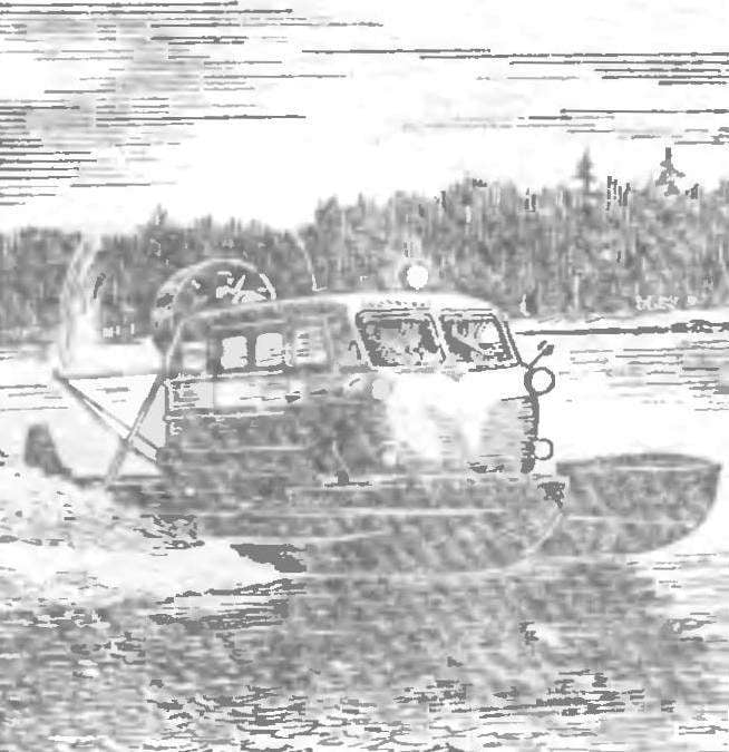
Originally performed by the screw AV-6 on a double snowmobile K-36 construction. I. Kamov (Fig. 4). His blades are turning crosspiece located inside the gearbox shaft. On the butt portions of the blades instead of levers mounted pins with wearing them on the crackers within the slot of the traverse.
 
Fig. 4. Propeller AV-6
 
Fig. 4. Propeller AV-6:
 
1 — housing grommet screw, 2, 6 — bolt, 3, 7 — lock washer 4 — nut, 5 — cover, 8 — Travers, 9 — thrust ring reverse 10 — key, 11 — pin, 12 — nut 13 — washer 14 counterweight, 15 — bolt counterweight, 16 — blade 17 — balance weight, 18 — blanking washer 19 — retaining split washer, 20 — o-cuff, 21 separator, 22 — balls 23 — biscuit, 24 — Cup blades, 25 — lock sleeve, 26 — snap ring 27 — screw preload, 28 — foot, 29 — the bottom of the glass, 30 — dowel counterweight.

 
Fig. 5. The control circuit of the air screw AV-6
 
Fig. 5. The control circuit of the air screw AV-6:
 
1 — traction control, 2 — lever, 3 — sliding clutch 4 — traverse 5 — blade, 6 — counterweight; And — the position of the blade “a big step”, B — “a small step” In reverse.

 
COMPLIANT SCREW
 
AV-6 — metal, two-bladed, pusher, right hand rotation (viewed in driving direction) the screw. Is driven by the engine MT-8 with a capacity of 38-40 HP and a gearbox. The frequency of rotation 2630 rpm, Ø1600 mm.
 
The type he — centrifugal mechanical, reversible, with fixing of the blades to direct the transfer of 8°30′, on the reverse of 19° 30′, ie the working range of stroke — 11°. The rotation angles of the blades measured at the radius of 600 mm.
 
Like structurally consists of a steel sleeve and two duralumin blades. Bushing installed on the flange of the gearbox. For fastening the blades to the hub is made of two nests, in which are inserted the special glasses. The latest turn in the separators with balls. The gaps are eliminated special screw tightness. Blades are turning crosshead moving on the dowel inside the shaft of the gearbox. At the ends of the impeller is located eccentric glasses fingers wearing them with breadcrumbs, sliding in the slots of the traverse.
 
Cross member moves in the longitudinal direction of the rod connected with the sliding clutch, which, in its turn, is connected by a rod with control levers (Fig. 5). On output IG of the sleeve ends of the cups with the blades installed counterweights and centrifugal loads. They are located at an angle of 20° ±1° and mounted on the dowels.
 
The screw runs in a straight line scheme: under the action of centrifugal moments generated balances, the blades are automatically set in the step necessary for that mode of movement. The translation of the blades in the reverse position is carried out forcibly by the special lever located in the driver’s cab Best the efficiency of the propeller is maintained throughout the range of the work.

Recommend to read

  • POTATOPOTATO
    Potato hasn't been easy work. Meanwhile, a simple Assembly can radically transform it, making it significantly easier. In appearance he is a one-wheeled wheelbarrow, but not the usual...
  • SHIELD AGAINST RUSTSHIELD AGAINST RUST
    Even well coloured barrel for rainwater, if it is to stand on the ground, will quickly rust away. Usually under the bottom enclose the bricks, but this is of little help, since the...