The need to have a nimble and reliable motorized assistant at my personal disposal I (like, probably, many others in a similar situation) felt with particular acuteness when I became the owner of a dacha plot. There wasn’t enough strength and funds for a mini-tractor, so I decided to limit myself to a walk-behind tractor, focusing on developments I found in the back issues of “Modelist-Konstruktor”.
I approached the matter creatively. The result — success, information about which was published in “Photopanorama” (“Modelist-Konstruktor” No. 10 for 1984).
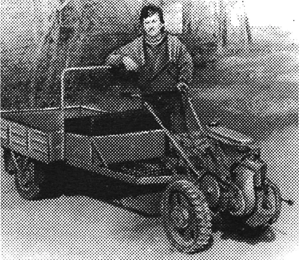
After the first walk-behind tractor assembled with my own hands, followed the second, third… And now here is — the fifth, successfully proven in practice design (fig. 1).
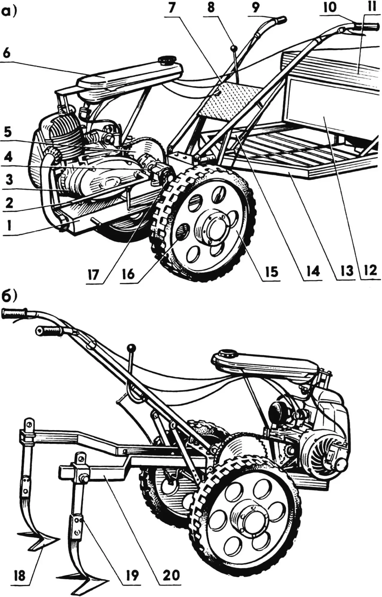
1 — frame-muffler, 2 — kickstarter lever, 3 — power unit, 4 — intermediate shaft unit, 5 — first stage chain drive sprocket, 6 — fuel tank, 7 — steering control block, 8 — gear shift lever, 9 — right handle with “throttle” lever, 10 — left handle with “clutch” lever, 11 — seat, 12 — tool box, 13 — “front” of cargo cart, 14 — trailer brake pedal, 15 — drive wheel (2 pcs.), 16 — overrunning clutch (2 pcs.), 17 — second stage chain drive sprocket, 18 — arrow-shaped cultivator tine (2 pcs.), 19 — cultivator stand (2 pcs.), 20 — D-shaped toolbar.
The walk-behind tractor is made with maximum use of industrial parts and assemblies. In particular, sprockets and chain PR-15.875 — from decommissioned agricultural machinery. As, by the way, are the overrunning clutches with rubberized wheels. As the latter, the “running gear” from GP-14 rakes serves quite well. But it’s quite possible to adapt what the creators of the widely used industrial walk-behind tractor “Krot” offer through the trade network.
The “energy heart” of the considered design is the T-200 power unit (or similar to it, such as, for example, on the “Muravey” cargo scooter). The intermediate and output shafts of the two-stage chain drive are installed in ball bearings 1680206С17 with tension sleeves (from the “Niva” combine straw shaker). Moreover, the housings of these bearings are fastened to the welded frame-muffler with M10 bolts, “locked” with nuts and Grover washers.
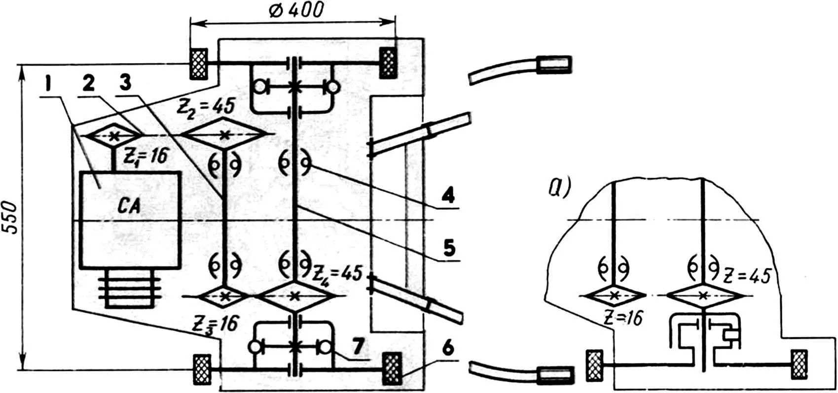
1 — T-200 power unit, 2 — chain drive, 3 — intermediate shaft, 4 — self-aligning bearing 1680206С17 (4 pcs.), 5 — output shaft, 6 — drive wheel (2 pcs.), 7 — roller overrunning clutch (2 pcs.); a — variant with ratchet overrunning clutch.
Fuel to the engine comes by gravity — from the fuel tank (taken from a motorized bicycle) installed on a bracket-brace (at the rear) and two 200-mm M8 studs (at the front). As many years of operation have shown, such a technical solution is quite justified.
In order for the walk-behind tractor to “behave” sufficiently stable during movement, the transmission of torque to the drive wheels is usually sought to be carried out through a differential. However, I did otherwise. Instead of an expensive differential, I risked using roller overrunning clutches from a decommissioned grain seeder. With certain lathe-fitter skills, they can, of course, be made yourself. Especially since each has only three (fig. 5) main, not so complex in manufacturing elements: cage, hub, and acting as a single whole triad of rollers.
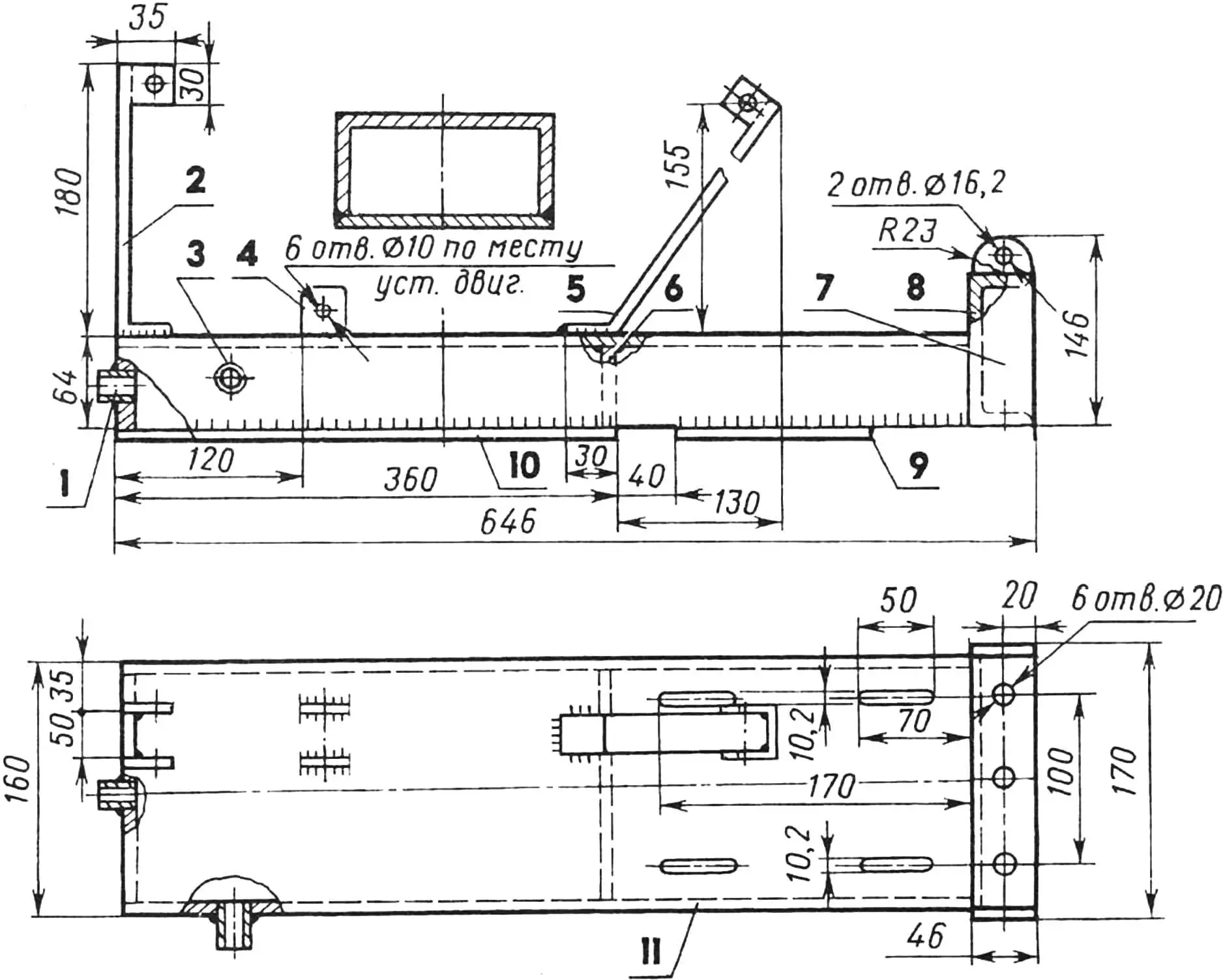
1 — inlet pipe (“stainless steel”, pipe 50х1.5 L30), 2 — vertical bracket (St3, strip s5), 3 — outlet pipe (“stainless steel”, pipe 20×1.5 L30), 4 — “lug” (St3, strip s5, 6 pcs.), 5 — inclined bracket (St3, sheet s5), 6 — sealing partition (St3, sheet s1.5), 7 — docking unit side (St3, sheet s5, 2 pcs.), 8 — cross member (St3, channel 100×46 L160), 9 — output shaft bracket (St3, sheet s7), 10 — muffler cover (St3, sheet s1.5), 11 — backbone beam (steel channel 160×64 L600).
When the hub rotates clockwise, the rollers automatically roll into the narrowing cavities and jam. As a result, the half-couplings engage to transmit torque in the required direction. If the driven part overtakes the driving part, the rollers roll out of the cavities, disengaging the “kinematics”.
Another variant of the walk-behind tractor has proven itself quite well — using a homemade ratchet overrunning clutch. The hub for it is made of structural steel and installed on the output shaft using bronze sleeves, pressed with interference, and then caulked. A grease fitting is provided for lubrication.
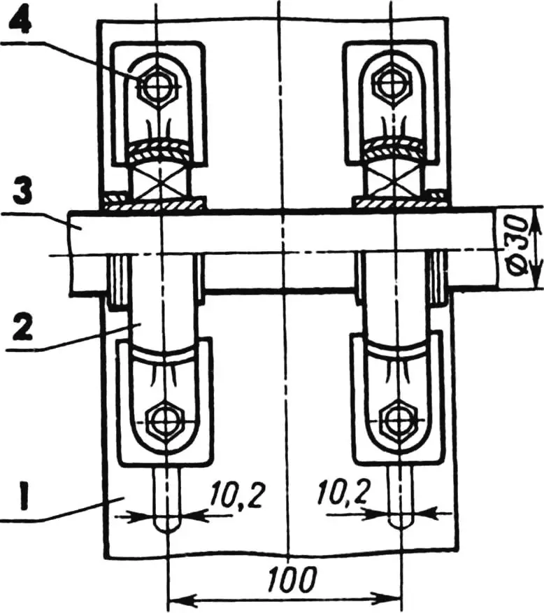
1 — backbone beam, 2 — self-aligning bearing 1680206С17 (2 pcs.), 3 — intermediate shaft, 4 — M10 bolt with lock nut (4 pcs.).
Axial displacement of the hub is limited on one side by a lock ring, on the other — by the overrunning clutch housing itself. Between them, to reduce friction losses, bronze thrust washers 2.0 mm thick are installed.
To attach the drive wheel disk to the hub, a flange is welded (marking of four holes on the latter — according to the disk). A ratchet is pressed onto the other end of the hub, which is held from rotation by a prismatic key. It is made from a 20 mm thick carbon steel sheet, has 12 teeth 7 mm high, inscribed in a circle with a diameter of 74 mm.
The overrunning clutch housing is fixed on the output shaft with three lock screws located in one plane at an angle of 120° to each other, for which corresponding recesses are made. The driven sprocket is attached to the disk with five M8 bolts (marking of holes on the disk — according to the sprocket holes). The pawl axis (fig. 6) is pressed against the ratchet by a spring.
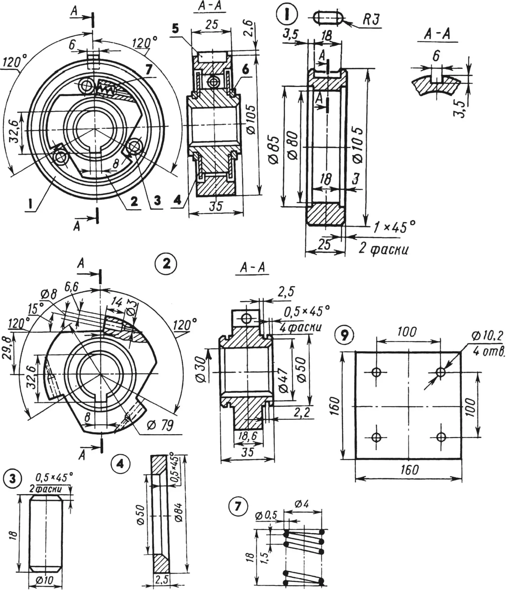
1 — cage (steel 20Х, HRC 56…62), 2 — hub (steel 20Х, HRC 56…62), 3 — roller (steel ШХ15, HRC 30…40, 3 pcs.), 4 — cheek (steel 45, sheet s2.5, HRC 30…40, 2 pcs.), 5 — prismatic key (steel 20ХН), 6 — split lock washer (2 pcs.), 7 — spring (steel wire Ø 0.5 3 pcs.).
The steering control block is telescopic, made from two pairs of steel seamless cold-rolled tubes that fit into each other. It is installed on the frame using a hinge connection that provides rotation of the walk-behind tractor in the vertical plane by 80°. This makes it possible to process the soil directly near shrubs and under the crowns of fruit trees. The “throttle” lever is located on the right handle, which regulates the position of the throttle valve. The “clutch” lever is located on the left handle.
The gear shift lever is on the right side. Moving it forward engages working speed, and moving it toward yourself — transport speed.
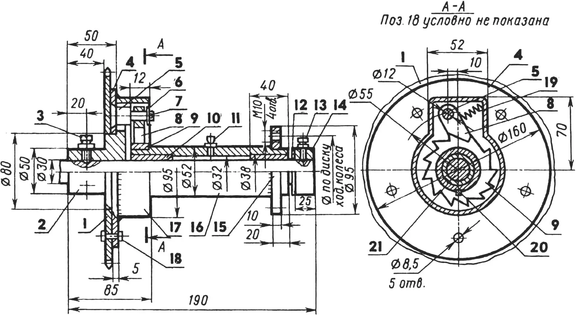
1 — sprocket (steel 20ХН, z=45 and t=15.875), 2 — housing (St3), 3 — M12 countersunk screw with lock nut (3 pcs.), 4 — disk (steel 20), 5 — pawl axis (steel 40ХН), 6 — washer, 7 — cotter pin, 8 — pawl (steel 20ХН), 9 — ratchet (steel 20ХН), 10 — sleeve (Бр05Ц5С5, 2 pcs.), 11 — grease fitting, 12 — thrust washer (Бр06Ц6С3, 2 pcs.), 13 — M10 countersunk screw with lock nut (2 pcs.), 14 — lock ring (St3), 15 — flange (St3), 16 — hub (steel 45), 17 — cover (St3), 18 — M8 bolt with countersunk nut (5 pcs.), 19 — spring (steel wire, Ø 0.8), 20 — prismatic key 4x4x18 (steel 45), 21 — output shaft (steel 45).
As already noted, the walk-behind tractor uses a T-200 power plant with a capacity of 14 hp with forced air cooling. On the frame it is mounted using vertical and inclined brackets made of 5 mm thick steel strip and three pairs of “lugs”, the holes in which are made in place during assembly. The tension of PR-15.875 chains in the two-stage transmission is carried out by moving the intermediate shaft in the slots of the backbone beam. The output shaft, like the intermediate one, also rotates in 1680206С17 bearings, only they are located at the bottom of the frame and are fastened using conventional bolted connections.
The entire drive is arranged in such a way that the center of gravity of the machine in the longitudinal and transverse directions to the maximum extent ensures the balance of the structure. For this, a slight pressure of the operator on the steering control handles is sufficient.
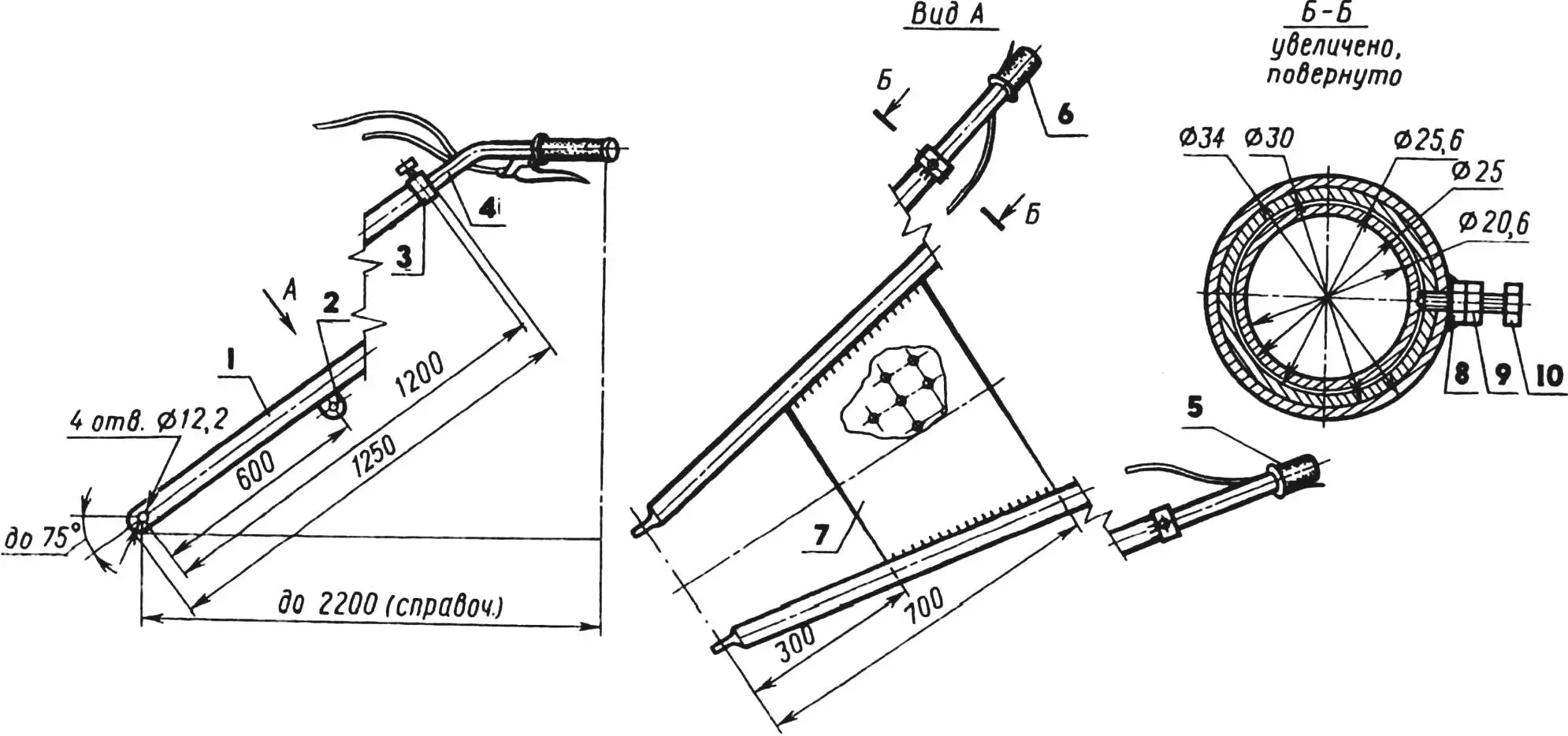
1 — main rod (steel pipe 30×2.2, 2 pcs.), 2 — “ear” (St3, sheet s5, 2 pcs.), 3 — sleeve (steel pipe 34×2, 2 pcs.), 4 — adjustment rod (steel pipe 25×2.2, 2 pcs.), 5 — left handle (with “clutch” lever from scooter), 6 — right handle (with “throttle” lever from scooter), 7 — perforated trapezoid (St3, sheet s3), 8 — welded M8 nut (2 pcs.), 9 — M8 lock nut (2 pcs.), 10 — M8 lock bolt (2 pcs.).
In addition, it was possible to practically avoid the occurrence of additional loads on the front part of the trailer’s load-bearing beam when using the walk-behind tractor as a vehicle, which fully agrees with the idea underlying the entire structure as a whole. After all, the machine was conceived as a kind of mini-tractor for work related mainly to moving cargo: with an improved cart from “Muravey”, with a comfortable (from PAZik) seat (tool box), with a reliable swivel drawbar and increased to almost a ton load capacity.
The walk-behind tractor fully justified these hopes.
As for soil-working tools, their attachment is carried out using a D-shaped toolbar (see fig. 1), installed in a box-type hitch, with rigid fixation by two 20 mm diameter pins.
WALK-BEHIND TRACTOR TECHNICAL DATA:
Dimensions, mm 650x860x1100
Weight, kg 580
Track, mm 550
Walk-behind tractor base with cart, mm 1800
Minimum turning radius
of walk-behind tractor with cart, mm 2120
Engine power, hp 14
Maximum speed
when transporting cargo, km/h ….25
Working speed during cultivation, etc., km/h 3.5
S. SHIRYAEV, Bekabad, Tashkent Region
Recommend to read
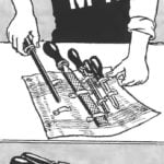 THE PLASTIC “DIAPER”
Like a baby in her wrap... instrument, and in this fold it is convenient to carry and easy to store. And minimized packaging does not even need tying: itself biases, since it is obtained...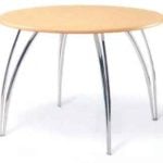 “ETERNAL” FURNITURE
We are accustomed to the fact that the furniture in the house or in the country are made usually from wood or materials on its basis, such as plywood. Wood, according to tradition, are...
