For 20 years the head of the circle “Ultralight aircraft” with guys of different generations built glider balance (1981); “the Antis” — single plane according to the scheme “duck” with the engine MP-800 (1985); a single aircraft with an engine from a snowmobile “Buran” (1994), the plane Argo, too, with the buranovskie engine (2000). The names of the planes “Antis” and “Argo” point directly to the prototypes which they constructed.
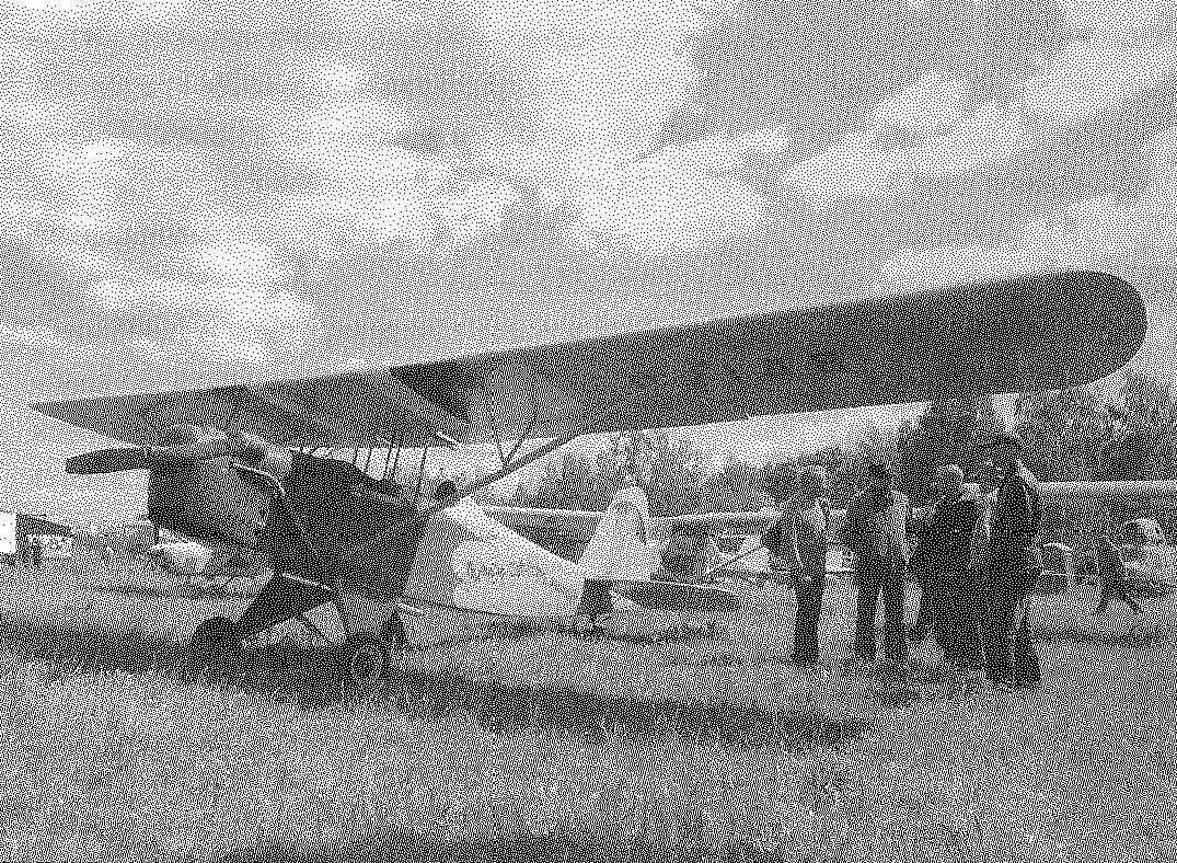
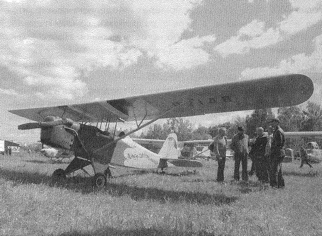
2 began to build, and two years later finished a pretty good and affordable costs the plane. For the prototype took another pre-war aircraft air-3 famous aircraft designer A. S. Yakovlev, although used structural solutions and other well-known and simple aircraft, such as the “Piper cub”, “Pietenpol”.
Our light aircraft is double the single-engine monoplane-parasol classic scheme with a controllable tail wheel. Designed for training flights.
The wing has a profile TSAGI PII relative thickness of 14%. Technologically the wing is divided into a center section and console. The center section is attached to the fuselage by four struts (front pair — struts). Rack made of pipes (steel 20) in diameter 36×1 mm struts from the same pipe, with a diameter of only mm. 25×1 Console, connect to the center section and using the struts with the fuselage. The struts are wing — oval profile cross-section 100×40 mm, glued from four pine plates with different direction of the transverse fibers (switching).
Double plane monoplane-parasol “Persistent”:
1 — propeller;
2 — reducer;
3 — the engine hood;
4 — front wing;
5 — canopy (2 pieces);
6 —cabin (2 PCs.);
7 — gargrot;
8 — fuselage;
9 — keel;
10 — rudder;
11 — tail wheel;
12 —tail wheel with the wheel;
13 — main landing gear;
14 — wheel main landing gear (scooter, 2 PCs.);
15 — silencer (from a motorcycle “Minsk);
16 — console wing (2 PCs.);
17 — pad(made of anodized aluminum, a sheet of 1.2).
18 — the center section of the wing;
19 — strut wing (2 PCs.);
20 — spacer (dural tube Ø20, 4 PCs.);
21 — the flap (2 PCs.);
22 — Aileron (2);
23 — the stabilizer;
24 —the Elevator.
Console wing:
1 — spar (dural tube D16T Ø110×2);
2 — root rib (pine rack 12×6);
3 — trim the root part (plywood s1);
4 — normal rib (pine rack 6×6);
5 — paludosa (plywood s);
6 — brace (tube D16T, Ø45, 2);
7 — strut with knizei (pine rack 6×6, plywood, s1, 2);
8 —front (intermediate) stringer (pine rail of triangular cross-section, a = 10);
9 — upper and lower stringers (pine rail s12x8);
10 — front side member (plywood s);
11— rear panel (pine slats 15×15 and 25×25, plywood, s1);
12 — the leading edge (plywood s1);
13 — end rib (pine rack 12×6);
14 — filler (foam,);
15 — ending;
16 — brace the ribs of the Aileron and flaps (8 PCs.);
17 — mount Assembly Aileron to the console;
18 — sock Aileron (plywood s1);
19 — spar Aileron (pine raked 10 x 10, plywood, s1);
20 — rib Aileron (fake plate s1);
21 — the trailing edge of the Aileron;
22 — transverse control rod Aileron (dural tube Ø8);
23 — the rocking chair;
24 —longitudinal control rod Aileron (dural tube Ø10);
25 — top bow (raked pine 6×6);
26 — the lower arc rib (pine rack 6×6);
27 — mejdurechye struts (pine rack 6×6);
28 — knize (plywood s1);
29 —bugey spar (dural tube Ø113×1,5);
30 —corner bracket;
31 — bracket mounting brace;
32 — ear plugs (front node) securing the console to the center section (steel, sheet s2, 2 PCs.);
33 —spar center section (steel pipe Ø40х 1,5), the situation;
34 — strut rear wall (pine rail 15x 15, the number of ribs);
35 — spacer spar of the Aileron or flap (pine rack 10×10, number of ribs);
36 — bracket (rear knot) securing the console to the center section;
37 — bracket quick coupling of the flap with the lever of its management.
Horizontal tail:
1 — stabilizer spar (pine bar-switching 40×35);
2 —rib stabilizer (lime plate s6);
3 — rear wall of the stabilizer (the pine bar 30×10);
4 — the toe of the Elevator (s plywood 1);
5 — spar of the Elevator (the pine bar-plywood 40×30);
6 —rib helm (lime plate s 6);
7 — the rear edge of the Elevator (the pine bar 30×10);
8 — knize (plywood s 1);
9 — pylon of Elevator control (steel 20, a sheet s 2);
10 — mounting brackets and strut brace (steel 20, a sheet s 2);
11 — the suspension unit of the Elevator to the stabilizer (2 PCs.);
12 — the tail part of the fuselage of the aircraft.
Chassis:
A — main bearings;
B — tail wheel
Motor plate and mounts it to the fuselage:
1 — motor mount (steel pipe Ø20);
2 — bushing (from the car “Lada”, 4 PCs.);
3 — bracket (steel, sheet s4, 4 PCs.);
4 — the fuselage
The plane “Antis” (1985), made under the scheme “duck”, had preceded the balance of the glider, which became the ancestor of the family clogo aircraft Privolzhskoi suit.
Double plane (1990)
Attachment points:
A — wing to the center section;
B — stabilizer to the rear fuselage and the linkage of the Elevator to the stabilizer;
In — the lever flaps;
Mr. rudder and the tail wheel support.
The plane with the engine from a snowmobile “Buran” (1994) and the penultimate development — “Argo” (2000)
The blade of the propeller
Control scheme:
A — the ailerons. Original version: mixed — cable runs and push-pull rods;
B —flaps;
In the Elevator;
Mr. rudder and tail wheel.
Equipment of the cabin — the dashboard and controls:
1 — lever engine control (ORES);
2 —handle control plane (RUS);
3 — switch ignition on;
4 — electronic tachometer;
5 — integrated control device operating parameters of the engine;
6 — failure indicator of the generator;
7 — the turn-and-slide;
8 — altimeter;
9 — speed indicator;
10 —variometer;
11 — clock;
12 – button engine start;
13 — the pedal arm (2 PCs.);
14 — pocket portable radio;
15 —seat;
16 — pristezhnye belts
Chassis:
A — the main strut;
B — tail wheel.
General characteristics:
Takeoff weight, kg……………………………………………………..600
Empty weight, kg……………………………………………………….435
Fuel capacity, l…………………………………………………………..70
Speed km/h:
separation………………………………………………………………………60
landing………………………………………………………………..40
cruising…………………………………………………………….100
maximum………………………………………………………….140
stall………………………………………………………………..40
The rate of climb, m/s………………………………………………….3
Run-up/run, m…………………………………………………….70/100
Wing
Scale, m…………………………………………………………………10,75
Area, m2…………………………………………………………………15
Chord, m……………………………………………………………………..1,4
Profile…………………………………………………………….R-P-14%
The setting angle, deg……………………………………………………..3
The angle of the transverse V grad. ……………………………………………1,5
The sweep angle of the leading edge, deg………………2
The magnitude of the Aileron, m………………………………………………………….2
The chord of the Aileron, m……………………………………………………….0,35
Deflection angles of Aileron, deg………………………………+30/-2
The scope of flap, m……………………………………………………..2.5
The chord of the flap, m……………………………………………………..0,35
The deflection angle of flap, deg…………………………………15
Chassis
Base, m………………………………………………………………………4,05
Track, m…………………………………………………………………….1,85
The size of the main wheels, mm…………………………………440×100
The size of the tail wheel, mm……………………………….185×45
Horizontal tail
The scope of the stabilizer, m……………………………………………..3,1
Root chord of stabilizator, m…………………………………1,08
The surface of the stabilizer, m2……………………………………….2,85
The installation angle of the stabilizer, deg………………………………-1
The chord of the Elevator, m………………………………………………….0,5
Area of rudder in m2…………………………………………..1,45
The angles of deflection of the elevators, hail……………………+30/-25
Vertical tail
The height of the keel, m………………………………………………………….1,36
The area of the keel, m2………………………………………………………1,38
The area of the rudder, m2…………………………………..0,88
The angles of rudder deflection, deg……………..+30/-30
Powerplant
Engine……………………………………………………….BA3-21083
Type………………………………………………………….carburetor
Max. the number of revolutions per min………………………………………5500
Max. power, HP……………………………………………………..70
Operating modes (power/vol.in min.):
Takeoff (up to 5 min.)…………………56/4700
nominal…………………………………………………….49/4100
cruising………………………………………………………43/3600
small “gas”………………………………………………………24/2000
Grade of fuel……………………………………………AI-92, AI-93
At the console side member of duralumin tubes with a diameter of 110 mm and a wall thickness of 2 mm (from plants), and the center section is made of a steel pipe with a diameter of 40 mm and a wall thickness of 1.5 mm. In places of fastening of the struts of the wing spars consoles are strengthened with bougie — sleeves with a length of 700 mm and an outer diameter corresponding to the inner diameter of the pipe member. At the end of a bougie for about 200 mm cut out wedges for a more uniform distribution of the load.
Subsequently, to provide the required longitudinal stability margin, the alignment of the aircraft shifted forward relatively to the mean aerodynamic chord, giving the consoles of the wing sweep angle. For this to the root end of the spar console had to priklopiti steel ear plugs with cover plates. Fasteners center section to the posts, and struts to the fuselage and a composite wing parts among themselves carried out by M8 bolts.
Ribs of wood. Recruited mainly from Linden slats cross-section of 6×6 mm (upper and lower arms, struts). Ear sock wing made of the same curved slats of variable section. Cnica — 1-mm plywood, and the front of the spar from 3-mm plywood. Each rib is threaded on the tube spar through the hole in the stand and fixed thereto by means of four aluminum angle brackets with rivets. In places of attachment of the wing struts to the spar and the strut end and root ribs riveted in eight points. Here note that the root rib are reinforced, their arms and the struts recruited from reek with section 12×6 mm. In the bow, along the console, the ribs are connected by three stringers; lower, front (middle) and upper. Between the ribs, from the front of the stringer to the top, installed additional half-arches from 3-mm plywood.
The rear wall of the wing stelleriana, hardwood, consists of two shelves (bars with cross section of 15×15 mm) and the wall (1 mm plywood), and serves to hinge the ailerons and flaps.
Wing sock from the bottom stringer to the top to ensure the rigidity of the profile trimmed with 1-mm plywood, and the rest of the bearing surface is covered with coarse calico cloth sewn to the force and form elements of the wing panels thread. A cloth soaked in a homemade Amalita with a solution of celluloid in acetone.
The attachment points to the wing struts, the only difference between the spar and the rear set of struts, made in the likeness of the past: a wall of 3 mm plywood and the shelf of slats cross-section 15×10 mm.
Rib Aileron and flap made of fake plates with cutouts to facilitate and spars from pine shelves 12×12 mm and walls 1 mm plywood. Socks Aileron and flap spars trimmed to 1-mm plywood.
The Assembly of parts of the ribs of the entire wing and fuselage were made on epoxy glue — proven binder. The wing skin fabric (coarse calico), finishing emelita.
The fuselage is a wooden truss, rectangular cross section. The basis of his power set are four pine longitudinal section in the front and middle parts of 20×20 mm and crossing at cross section 16×16 mm — in the rear. The spars are connected to the farm through the uprights and crossbars of the same cross-section. The nose and tail parts fuselages 3-mm plywood. The middle part is augmented by braces, and is covered with coarse calico cloth.
The tail Assembly is wooden with braces. The stabilizer consists of a spar and the rear wall with ribs between them and sheathed impregnated Amalita cloth. The back wall is hinged the Elevator, consisting of two halves. The bow of the steering wheel to the longitudinal sewn 1 mm plywood (like the wing) which receives the load in torsion, and the rest of the surface is covered with impregnated cloth.
Vertical tail: the keel and the rudder is made similarly to the horizontal tail. Control the rudder cable and Elevator — mixed.
Chassis — pyramidal with the main wheels of the scooter “Tula”. Main landing gear is made of pipes with diameter 36×1. 5 mm, they are connected pivotally with the lower longerons of the fuselage via four angled bracket. Dampers — spring. Tail wheel — driven, with a rubber plate absorber and wheel dimensions 200×80 mm.
The engine frame is welded from pipes (steel 20) section 20×2 mm and fastened to the longerons of the fuselage using the four brackets-pads. The engine fit in with it at four points through bushings.
As the power unit rotor in installing a used engine with
tel from the car VAZ-21083, and without alterations, the exhaust manifold is fitted the muffler from a motorcycle “Minsk”. Torque from the engine to the propeller is transmitted through the makeshift gear reducer with a gear ratio of 2.6. Pinion gear (27 teeth) — a motorcycle “IZH-Planeta-Sport”, driven (70 teeth) — a homemade, their shafts are turned from the shaft of the gearbox of the truck GAZ-51. The gear housing is welded from steel of 3 mm sheet and processed using simple devices on the school lathe and milling machines. Fuel tank capacity of 50 liters is located in the forward fuselage.
Propeller with a diameter of 1.6 m — pull, one-piece two-blade, wooden (plywood of pine sticks) covered with two layers of fiberglass cloth on the epoxy binder, with edgings of brass sheet. Later he was replaced by similar, but with a diameter of 2 m. At the same time had to raise the height of the axis of the screw, what made
narrowing of the track chassis. The propeller develops a thrust of 150 kgf at takeoff.
Controls and instruments are mounted in both cabins. Control of the plane (Elevator and ailerons) — from either of two handles connected by a rod and located in front of the seats in each cabin. The deviation of the rudder and rotation of the tail wheel produced simultaneously from the pedals through the cable runs. Engine management — from the lever mounted to the left of the pilot. The flap control is carried out from the handle-lever with the lock in the pilot’s seat from the rear of the cab.
The aircraft is equipped with devices controlling the engine and ensuring flight in simple meteorological conditions. They are all located on instrument panel in both cockpits.
Seat is hand made, equipped with pristezhnye belts — automotive belts.
The aircraft underwent a technical Commission and registered in FLA in 2002. Today its flying time in excess of 500 hours (2412 landings). After 500 flying hours was produced audit engine. Wear of rubbing parts not yet discovered.
During the operation of the aircraft design was modified, although not dramatically. So, over time, a cable control with ailerons replacing the hard. The cabins instead of the sides for the convenience of the pilot and passenger did on one side of the folding doors. Changed the design of the tail support and the location of the foot. The main landing wheel is equipped with a mechanical brake driven lever to the handle via
cable budenovskoy braid. Before booths set пр9зрачные peaks of 5-mm Plexiglas, the pilot’s headrest, and the seat back in the rear cockpit organized a small trunk. Strengthened the attachment of the stabilizer front strut. Changed the painting of the aircraft.
At the end of may 2008 our team plane “Persistent” once again took part in the national gathering of aviation enthusiasts in the city of Vladimir. Annual flight to the rally and back showed that the plane is able to overcome the distance, and a few hundred kilometers without landing.
Suggest aircraft enthusiasts: bolder build a simple aircraft. They are available to all. Just be persistent and believe in yourself, and then you will succeed! Success!
V. RUMYANTSEV, Privolzhsk, Ivanovo region.
Recommend to read RIVER BOAT This model can successfully build students 4-5 classes. Best to start with the housings. It can be done chiselling from a block of wood or stacked. If the housing is stacked, panel it... CUTTING TRIPLEX I'm sure many amateur car builders face the problem of glazing the body when building their vehicle. Most of them solve this by "tying" themselves to the sizes and shapes of automotive...
 So call your plane the club-model airplanes and their leader — Vadim B. Rumyantsev from the city of Privolzhsk, Ivanovo region, whose hands at the local station of young technicians (syt) it was created. They say that recreational aviation is an expensive hobby, and it’s hard to disagree. But, after familiarizing with the design of the aircraft, it becomes clear that the materials used in its manufacture, and power plant, which it is equipped, not scarce and not so expensive. It seems that such aircraft can build even those who have financial resources, that is, below average. Of course, one of Finance and a love for aviation for self-built aircraft is not enough. Need special knowledge, skills, and it’s still — enviable tenacity in achieving their goals. That’s why the boys and their mentors give the plane a name is “Persistent”. Today, E. B., Rumyantsev talks about his plane readers.