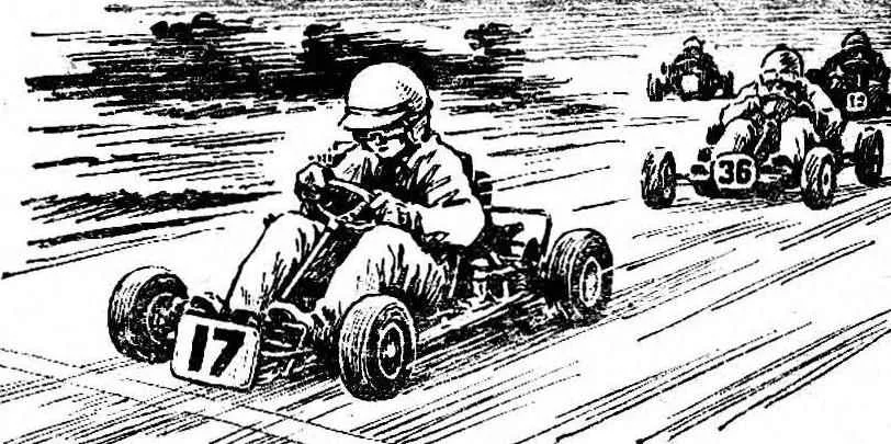
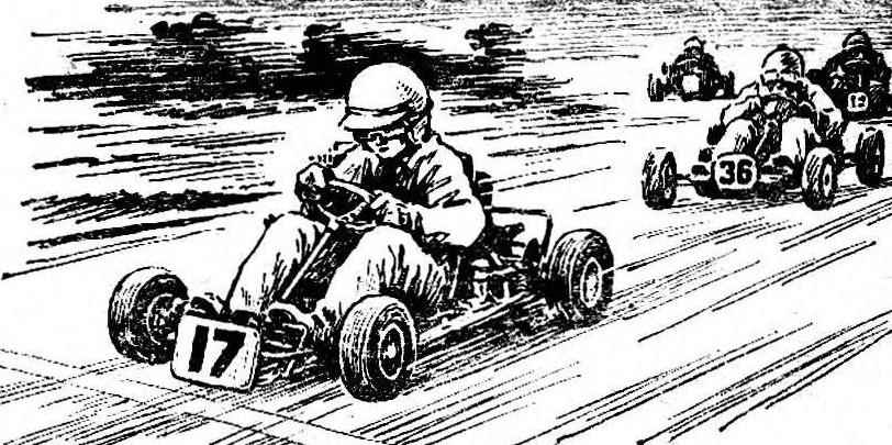
 Class cards pioneer is the smallest of the sports racing cars. The working volume of its engine is only 50 cm3. These cards are build for racing, involving boys aged 9 to 16 years. Unfortunately, the industry these machines are not yet released, and they are created in sections and circles.
Unlike “adult” go-karts “pioneer” has its own design features. Frame it, for example, welded from thinner tubes and has a wedge shape. It is inherent manufacturability and reliability. It has the advantages over their own kind, and in stiffness and strength. By the way, this configuration of the frame we make for go-karts not only class “a pioneer” but also “Junior” and “Union”.
The initial construction phase – development of drawings and preparation of fixtures and tooling. The frame is most convenient to draw life-size on a sheet of graph paper, pasted on thick cardboard. Such a drawing will subsequently serve as Plaza, which essentially are adjusted to the individual elements.
Draw the frame you need two views – top view and side view. Separately draw the front spar. Don’t be fooled by the lack of certain dimensions in the drawing – this means that items here should fit in place.
The next stage is the production of slipway to build the frame. You will need it in case if you are going to produce these cars in small series.
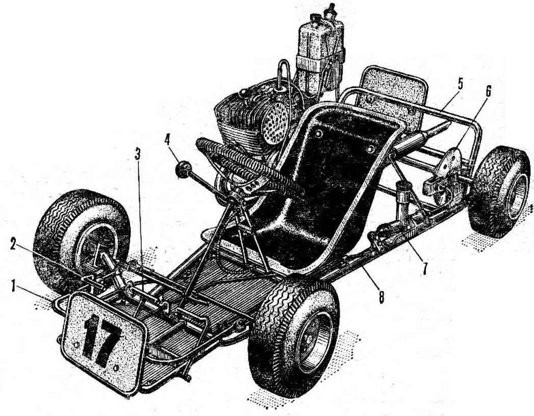
Fig. 1. Class cards Pioner:
1 — front upper bump stop,
2 — the gas pedal,
3 — brake pedal
4 — gear lever,
5 — rear bumper
6 — brake disk
7 — brake master cylinder
8 — frame.
The base of the pile – sheet of aluminum the size of 1700X900 mm thickness of 15-20 mm. Along its long axis, a clear longitudinal line is the trace of the plane of symmetry of the frame card and perpendicular to it – the baseline for setting of clamps pivot bushings. The holes in the latter must be cut for boring machine – this will provide the necessary accuracy of installation of bushings during the welding of the frame.
 On the stocks are also installed steel angles for fixing to the longitudinal spars.
The frame itself is assembled from two longitudinal side members, three cross members (front, middle and rear), front bumper and mounting bracket of the steering column. For its elements preferably hromansilevyh (material 30KHGSA) or seamless pipes of steel grade 20.
The procedure for their preparation is as follows. Cut the pipe with an allowance of about 30 mm and bend with the help of fixtures on the drawing-Plaza. This operation is best performed without heating. Offer several of the most rational ways of such processing.
Most just bend the pipe with the use of inserted inside of the spring wire grade optical fiber. It screws onto the lathe and then be sure to normal. For thicker tubes will require wire dia. 2, 5-3 mm, and for the rest of the dia. 1, 5-2 mm. Outer diameter of the spring should be such that it is inserted into the pipe with some force.
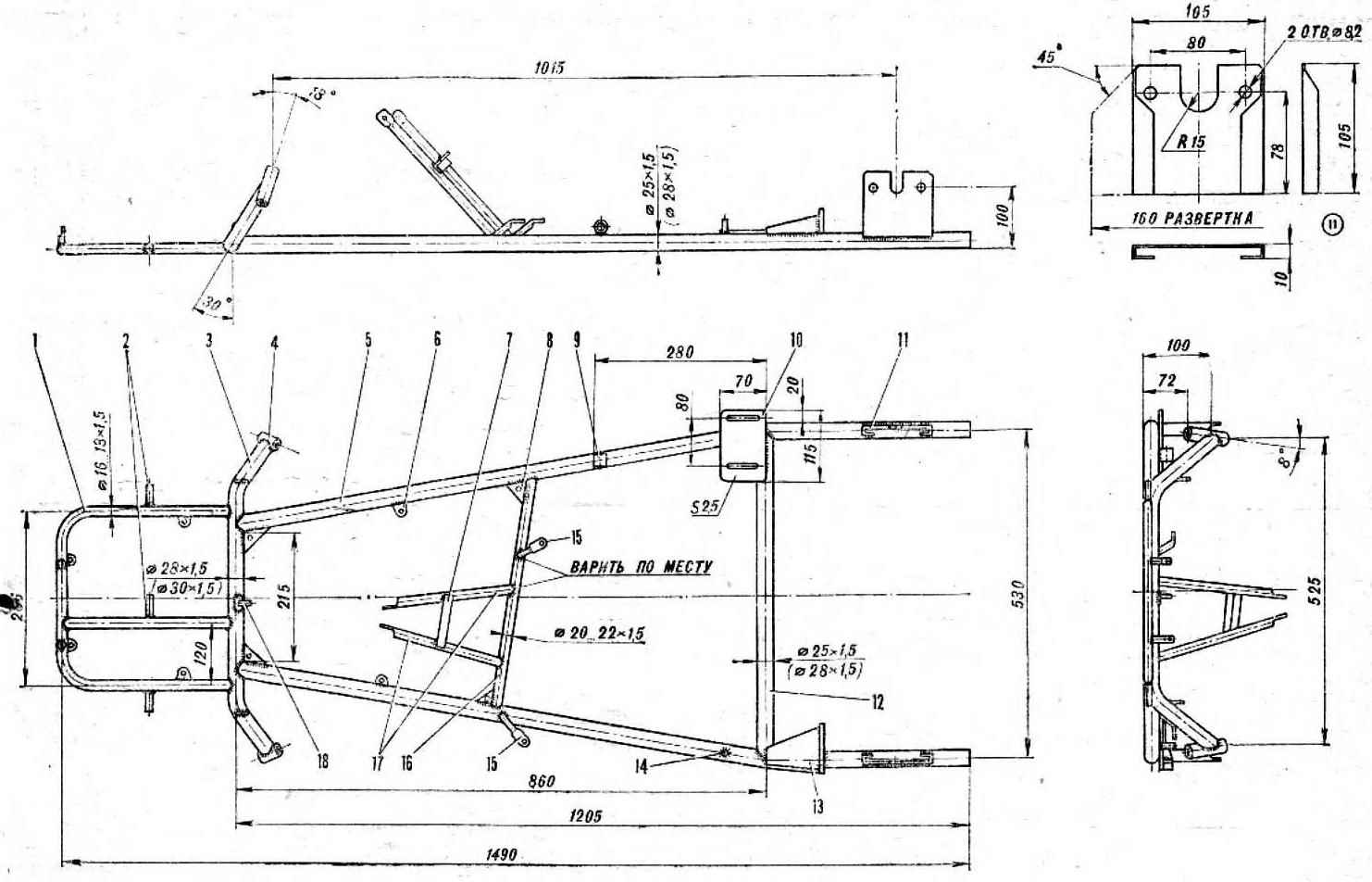
Fig. 2. Frame card:
1 — front lower bump stop,
2 — axis pedals
3 — front cross beam,
4 — pivot bushings,
5 is a longitudinal spar,
6 — mounting bracket floor
7 — bracket of the shift lever,
8 — solitaire,
9 — front engine mount,
10 — back support,
11 — bracket rear axle
12 — rear cross member,
13 — mounting bracket brake master cylinder
14 — the axis of the brake lever
15 support, seat,
16 — the middle cross member,
17 — steering column bracket,
18 — axis-walkera steering column.
If the frame map is made in winter, before the flexible pipes can freeze water. A good effect is the pouring of molten rosin.
Finally, the traditional method of processing with gasket sieved and calcined sand. The pipe easier to bend by heating the bend with a burner flame or blowtorch.
But this method is less preferred because heating of the steel alloy greatly reduces its strength and elasticity.
Giving the blanks the desired shape, adjust – prepelita them to each other so that the joints do not leave gaps. This work start with the installation on the frame front cross member (mid align the centerline of the pile). Further, on one side install the retainer with pivot bushing and will adapt to it the crossmember so that the resulting plane was inclined at an angle of about 30° to the vertical. Perform the same operation on the opposite side of the bench.
The thus prepared front cross member to align the staple to the staple and it propylite longitudinal spars. To the last the same way attach the rear crossmember and the front crossmember – bump.
All the elements of the frame lock on the stocks staples and clamps, check again their position and start welding. The best seams are obtained when using argon arc or carbon dioxide welding, some of the worst results are obtained by conventional welding. Gas should be used last.
Weld the frame in several stages. First “tack” the weight of the joints – each in one or two points and then weld them completely. Without removing the frame from the slipway, to weld the mounting brackets of the engine and the rear axle. The last pre-put on the axle – this will help to ensure the perpendicularity of the plane of symmetry of the frame.
The axis of the pedal brackets steering column, Central crossmember and supports, the seat should be welded only after the preliminary “fitting” map to the driver. The lower part of the seat is at the same level with the troughs of the side members of the frame. Correct landing of the driver has the following characteristics: the back is tilted backwards at 20-25°, the legs are slightly bent at the knees.
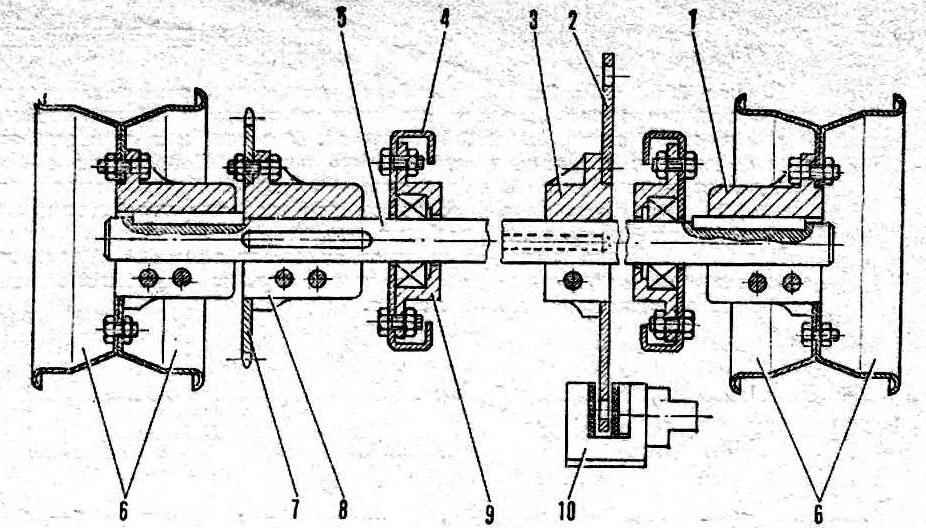
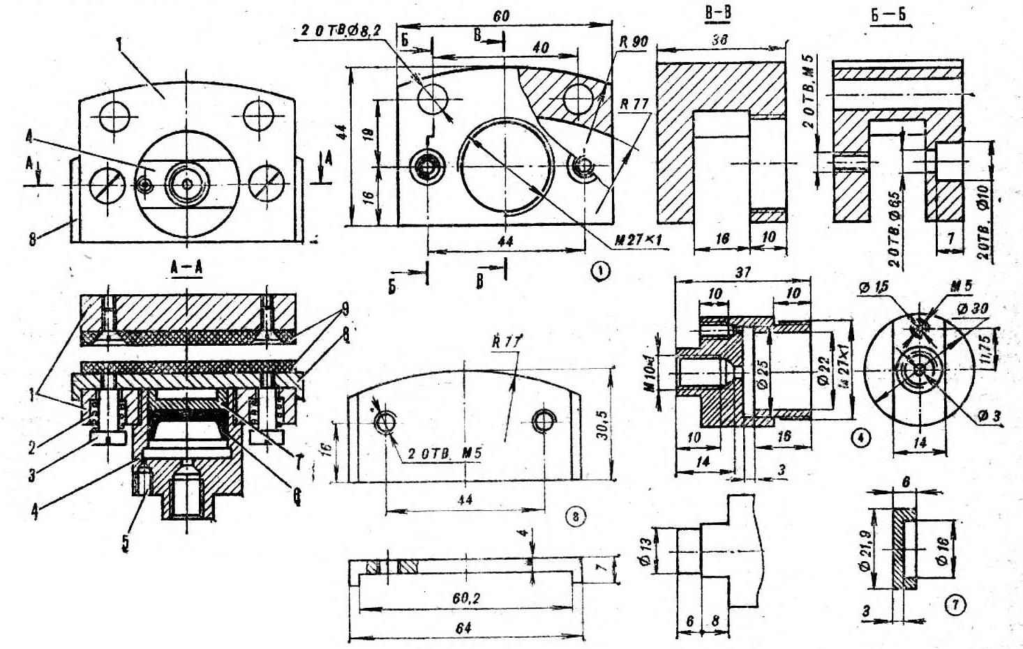
Fig. 6. Rear axle:
1 — wheel hub,
2 — brake disc,
3 — the hub of the brake disc,
4 — the support bracket of the bridge,
5 — shaft,
6 — wheels,
7 — star
8 — hub sprocket,
9 — bearing housing,
10 — brake machine.
The latter are welded lugs mounting floor brackets and tubes, front upper bumper gusset plate at the joints of the longitudinal side members front cross member and lugs of the shift lever, and stops cables.
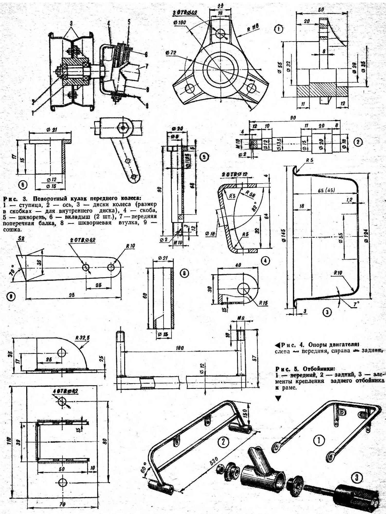
For the front axle will need a few turned parts, particularly the front hubs (D16T), axles (from 30KHGSA), bronze bushings and pins steel 45 or 40X.
The eyelet of the front axle it is best to bend of steel strip with a size of 40X30 mm on the pattern. It would be to weld a lever, amplifying the scarf and last axle.
The design of the rear axle is quite simple and technological. Hub bearing housings are cast from aluminum alloy with subsequent fine machining on lathe and milling machines.
Brake map – disk hydraulic drive. According to the specifications of class cards “pioneer” equip only brake the rear wheels.
The brake disc is fixed to the rear axle chart and the frame mounted brake machine. The body is duralumin, steel cylinder (30KHGSA or CT. 45). The piston is made of brass or of material D16T.
You can use the front drum brakes of the scooter T-200 or motorcycle M-106. When installation should pay careful attention to the alignment of the brake drum.
For the selection of the optimal gear ratio chain drive of the rear axle it is recommended to develop a set of driven sprockets with number of teeth from 22 to 28 with an interval of two teeth. This will greatly facilitate the adjustment of the actuator under the weight of the card and the rider, engine power and frequency of rotation of the drive sprocket.
Rims map can be made of aluminum alloys Д16АМ or AMG-6. The stock thickness of 2-3 mm. the extruding Method of disk following. First of any metal machined punch. The preform is drawn in to it, the tailstock of the lathe and secured in the tool holder is driven around the roller until then, until take the form of a punch. Processing is carried out at frequency of rotation of the Chuck of the machine from 150 to 300 rpm, as a lubricant used in conventional soap.
Brake machine:
1 — caliper
2 — spring
3 — screw attachment of the lining,
4 — brake cylinder,
5 — hole for the pumping cylinder,
6 — rubber collar,
7,a piston,
8 — brake pad,
9 —friction, plastine.
The holes in the rims best drilling pattern-the conductor. Last, it is desirable to make the steel and tempering. Do not take on this work, especially if you decided to build a few cars.
Mount the front wheels, tie rods and pedals need to splitout; acceptable and self-locking nuts.
As mentioned, the maps-class “pioneer” is allowed to install engines with cylinder capacity of 50 cm3, in particular, domestic engines Sh51, sh-52, sh-57, sh-58 and sh-02. Should not immediately be taken for the crossing of the engine – it will dramatically reduce its life and reliability. We just need to properly adjust the carb and ignition. First, you’ll be fine.
For tank it is best to use a plastic canister with a capacity of 2 L. to Place it on the map should be so the fuel gravity flowed to the carburetor. In the lower part of the container is inserted into the fitting or valve, and in the tube canisters drilled hole through which is passed a PVC tube.
The chain tension the engine is regulated by a stop – thunder with two pressed in his ears bearings SHS-8. If the thunder under the runes will be, weld on the frame nut M10 screw and bolt in it so that it rested in the bracket of the engine.
The chain top is closed with flap of plastic blocking half driven sprockets. The width of flap 30 mm.
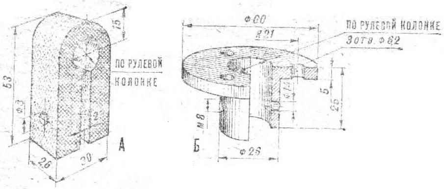
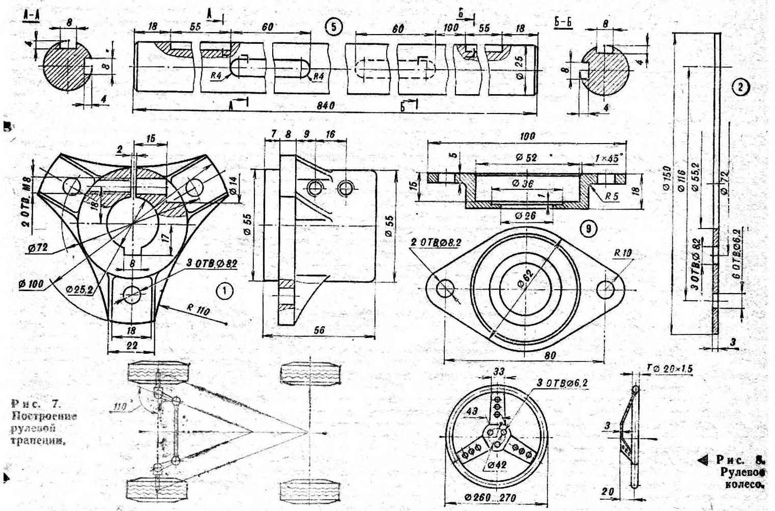
The steering column is mounted on arm’s length athlete (brush grips the top part of the donut). This is steel pipe dia. 18 mm; in the lower part of her welded rotary soshne – arm of steel strips with a thickness of about 2 mm. When butchering in the fry hole for the tie rod, it should be remembered that the optimal ratio dlim of the knuckle of the front wheel and shoulder bipod is 1.7:1.
Rods – tubular, the ends are tucked in the sleeve bearings RC-6 or RC-8, at least the rubber bushing. After Assembly, check operation of steering mechanisms: the axle should turn at an angle of about 35°. If the angle is more, make the stops.
Steering wheel arches cold pipe brand AMG or AMC with external dia. 22 – 25 mm and wall thickness 1,5-2 mm. Tube Packed with sand and multiple circumferential coils on a suitable mandrel, for example, a gas cylinder. Thus obtained the workpiece for several “bagels”. The spokes are cut from 4 – to 5-mm aluminum sheet brand AMG, or AMC. Warn that to do the spokes from the “hard” alloys D16T, Д1ЭТ, V95 and the like is not recommended – in the field of welding cracks can form, and the wheel will collapse. Then the steering wheel with three bolts attached to the bearing of the steering column, sheathed in leather or imitation leather with pre-covering of microporous rubber or foam.
Brake pedal, gas and clutch the curvature of steel pipes diam. 12×1,5 mm. Rings, which are attached to them cables and struts are connected with the pedals welding. When assembling be sure to install the pedal return spring.
Pauline is made of duralumin sheet thickness of 1.5 mm; it is attached by means of screws to lugs welded to the frame.
The seat is the easiest way to applied to the wall of the fiberglass, using a “dummy” seat map of the Leningrad plant DOSAAF. When Vileika shell put on the dummy spacer layer of flooring mastics. To paint the seat preferably not after vilami, and immediately, mixing epoxy resin with a black pigment.
The front seat is attached to brackets welded to the frame map back to the two adjustable tubular supports.
Ate test Assembly, the debugging and tuning of all mechanisms of the machine must be completely disassembled. Frame thoroughly cleaned of rust and scale, degrease, primed and painted with nitro or synthetic enamel. Bumpers, steering column, pedals, steering rods and the shift lever is preferably a chromium coating. The steering knuckles of the front wheels can be painted in black color.
Rooms map cut out of plastic, their dimensions – 220Х220 mm. the Corners of the square should be rounded at a radius of 20 mm.
KRUGLIKOV, head of club karting Palace of pioneers of the Bauman district of Moscow.
Recommend to read
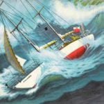 “POLONAISE” BY VLADIMIR BARANOVSKY
The first time I saw "Polonaise" in the picture. He was standing on one of the Central squares of Warsaw, surrounded by a dense ring of spectators. Interest in the yacht and its captain,...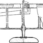 CLASS F2D: NEW TECHNOLOGY
In recent years, modelers have increasingly used in their designs packing foam. This material is lightweight, sufficiently durable, uniform and well handled by termoindurente — Izanami...
