PLOWS, CARRIES AND EVEN SAWING

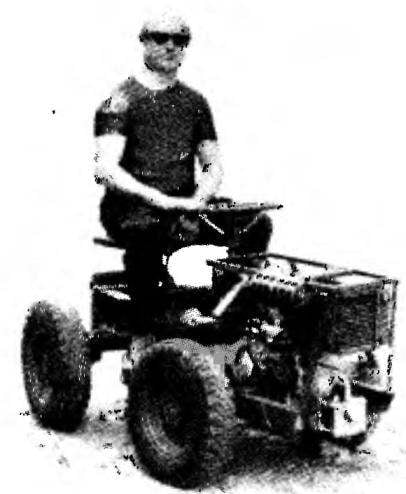
PLOW, CARRIES AND EVEN SAWSThe need to build a mini-tractor came to me simultaneously with the acquisition in the early 80-ies of the garden plots (receiving, as they said then). Those coveted six acres it was necessary to develop and sustain. I wanted to build a country house. Without mechanized assistant in this matter to do would be difficult. Industries such machines at that time almost was not allowed to get them even an acquaintance, it was almost impossible unless you’re a war veteran.

In many respects the design of the mini-tractor determined that the building site there was no electricity, and therefore the engine of the tractor was to be driven for many construction machines: concrete mixers, circular saws etc. and that time I had the engine D-3 with all devices necessary for its operation: carburetor, magneto, radiator. Same engines for generator drives stood in the middle of the last century in those rural clubs, where there was no electricity, which is produced by using such engines to be able to “twist” movie. This motor became the “heart” of my motorized assistant.

Gearbox taken from the ZAZ-965, wheels — motorized FDD. Other nodes are homemade, including space frame. It is made mostly out of channels and angles of various sections. Welding then I have never had and therefore all its power connection parts — bolt-M10 and the auxiliary — bolt-on MB. Edges with spacers on the rear frame are connected by rivets.

 
Universal mini-tractor (side view of the left wheel is not shown)
A versatile mini tractor (side view of the left wheel is not shown):
 
1 — kick-starter; 2 — engine D-3; 3 — radiator; 4 — front of the frame; 5 — fuel tank; 6 — the steering column; 7 — the lever of a gear change; 8 — the mechanism on the PTO shaft; 9 — seat; 10 — rear of frame; 11 — flange PTO shaft; 12— damper; 13 — wheel reducer (2); 14 — rear axle beam; 15 —the left footrest; 16 — basket of the clutch and transmission; 17— hood; 18 — tube fuel tank and radiator; 19 — wheel (sidecar FDD, 4 PCs.)
 
Front of frame (all connecting parts bolt M10)
Front of frame (all connecting parts, bolts M10):
 
1 —axle front wheel (steel 45 , d85, L138, 2); 2 — longeron (channel № 8, 2); 3 — brace (area No. 7,5, L165, 2); 4 — solitaire (D16, the sheet s10, 100×100, 2); 5 — gon eyes (area No. 6,3, L154, 4-piece); 6— (corner № 6,3, L368. 2); 7— sub bracket (STZ, the sheet s5. 180×165, 2); 8— yoke (channel No. 5, L435); 9 — the section of the attachment wheel drive (area No. 6,3, 2); 10 — strut bracket (STZ,the sheet s5, 190×156); 11 —plank (D16. sheet s5, 170×20, 2 PCs.)
 
Rear frame
 
 
Rear of frame:
 
1 —eyelet (aluminium, s40, 2); 2 — (channel No. 5, L315, 2 pieces); 3 — bushing (bronze, pipe 20×4, L40, 2); 4 — connecting plate (STZ, the sheet s10); 5—casing (steel 45, steel 140×20, L120); 6 — pin M12 coupling (steel 25, rod d12, L150, 4-piece); 7 — bearing 1000915 (2 PCs.); 8 — swivel bushing (steel 45,d80x10, L185); 9 — horizontal edge (steel, corner № 6,3, 4 pieces); 10 — cross member (steel, corner № 6,3); 11 — rear plate (D16, sheet s 10); 12 — rear axle beam (steel, channel № 8, 2); 13 — axis bracket (steel 45. 2); 14 — axis of the rear wheel (sidecar FDD); 15 — spacer (steel 20, a sheet s2, 298×110); 16 — Circlip (45 steel, sheet s15, d90); 17 — pin (steel, rod d6,4 pieces); 18 — side pad (steel, corner № 6,3, 2 PCs.)
 
PTO (PTO)
The shaft of the power take-off (PTO):
 
1 — the mechanism of the activation of the PTO; 2 — output shaft of the mechanism; 3 — the first knee TION with a fork; 4 — front cross-piece; 5 — front of the frame; 6 — upper bolt-hinge pin vertical axis “fracture” frame; 7 — flange joints; 8 — back spider; 9 — rear frame strut with a linkage plate; 10— second knee TION with a fork; 11 — bearing 206 (2); 12 — spacer; 13— the case of the front bearing unit; 14 — joint; 15 — swivel bushing; 16—bearing 1000915 (2); 17 — a lock ring; 18 — pin(4 PCs.); 19 — third knee TION; 20 a bearing 205; 21 — drive flange
 
The drive of the drive wheel
Drive driving wheel:
 
1 —disc wheel (sidecar FDD); 2 — hub; 3 — adapter (steel 20, a sheet sl8, 0180); 4 — outer spacer (steel 20); 5 — ball bearings 205 (4 PCs); 6 — M10 screw; 7 — outer cover; 8 — axis; 9 — inner spacer (steel 20); 10 — HIIT MB fixing the outer cover (6 PCs); 11 — an internal cover (steel 20); 12 — nut M10 fixing hub (6 PCs); 13 — screws M10 wheel fixing (6 pieces); 14 — gear-housing (STZ, listug); 15—driven gear (z = I7,m = 3); 16—bandage (steel 20, sheet s25, d275); 17 — the drum (modified brake disc car); 18 — spar front frame; 19— pin (45 steel, 3 pieces); 20 — bearing housings (steel 20, 2 PCs); 21 — washer (steel 20, d15x3, 6 PCs); 22 — a bolt M8 (6 PCs); 23 leads (45 steel); 24 — shaft; 25 — a cover with a cuff; 26 — bolt M8 attaching a leash; 27 — plate-drive (VT-1-0, sheet s0,5, 80×80, 4-piece); 28 — protective washer (rubber); 29 — spacer ring (steel 20); 30 — spacer (steel 20); 31 — the cover of the casing of the reducer (STZ, sheet s2, 410×340); 32 — drive shaft gear (z = 67, m = 3)


The main feature of the frame — it is articulated, like a real big tractor (To-700 or T-150), and consists of two half-frames: the front (under engine) and rear (steering).

 
The complexity of designing a turning point of the node was that it had to pass also the PTO shaft. But I managed to solve this problem simply by skipping the intermediate cardan-knee-shaft in its bearings through the swivel bushing and securing the rear end of the shaft in the bearing Assembly, mounted on the “transom” plate rear articulated.
 
The front frame contains almost all the units and mechanisms: engine with gearbox, petrol tank, gear the front driving wheels, the driver’s seat.
 
On the rear of the same frame — only the bearing assemblies and rear axle beam. This frame part has the ability to rotate not only about vertical and about a horizontal axis, thereby eliminating the hanging rear wheel on a rough road. This opportunity provides a front bearing Assembly. Its outer body is rigidly connected by studs with horizontal fins articulated, and the inner swivel sleeve is welded to the transition plate, which, in turn, too tightly drawn by bolts to the posts critical of the site.
 
The suspensions of wheels like those mini-tractor no. The axis of the front wheels rigidly attached to the side members of the front articulated. The axis of the rear wheel also rigidly mounted in the brackets tightly privernuty bolted to the channels of the rear beam. Depreciation chassis is due to the optimal air pressure in the tires of wheels, especially because it is easy to determine, because the weight of the tractor is almost constant.
The engine was initially installed D-3 — single-cylinder, four-stroke, liquid cooled. The motor is started by the kick starter, ignition from magneto. Working on the lowest grades of gasoline, the engine remained unpretentious and reliable. His main drawback—a small capacity, only 3 HP So when I bought the engine UD-2 with 8 HP, then immediately mounted it on a mini-tractor. This motor is two-cylinder, forced air cooling. The frame was not altered, only replaced under engine brackets. However, I had to set another connecting plate for connection to the engine transmission clutch basket. These transmission units from the car “Zaporozhets”. Box with basket rotated by 180° relative to their position on the car. For this reason, the wheel reducers are designed so that they not only reduced speed but also changed the rotation transmitted from the gear box axle shafts on the reverse.
 
Large transmission ratio of wheel reducers allowed to do without brakes. The speed and weight of a small tractor, and he quickly stops when “squeezing” the clutch by itself.
 
On PTO
The mechanism on the PTO:
 
1 — gearbox; 2 — dowel; 3 — stud M10 fastening mechanism; 4 — a cover (D16); 5 —pinion (steel SOHGS); 6 — housing (D16); 7 — cover (D16, the sheet s8, 70×50); 8 — lead (steel 45); 9 — the screw of the locking position of the slider; 10 — the lever (steel 25); 11 — lever axle (45 steel, rod d8, L50); 12 — slider (45 steel, rod d12, is l105); 13 — drive shaft (сталь45, rod d25,225 1); 14 —104 ball bearing(2 PCs.); 15 — cover (D16, листв8,90×50); 16 — restrictive bushing (steel 25)

 
Mini-tractor
Mini-tractor “bundle” with wood-working machine
 
Of the wheel from the sidecar FDD came to design the mini-tractor is the best not only by mass but also by size. Everything, wheels rims these wheels — restrictor small, and he quickly stops when “squeezing” the clutch by itself.
 
Of the wheel from the sidecar FDD came to design the mini-tractor is the best not only by mass but also by size. Everything, wheels rims these wheels is separable, which greatly simplifies disassembly for repair camera in case of puncture.
 
Office mini tractor although not quite common through the broken frame, but there is a serial steering (of the car “Moskvich”) and linkage with servo horns and mounting brackets.
The PTO shaft (PTO) is driven in rotation through the makeshift gear mounted on the transmission. A handle on the housing of the gear mechanism, planted on the shaft of the mechanism and is engaged with a gear box input shaft speed, transmitting the rotation of the multistage Sustainable. Multi-layered due to the “turning point” frame design and so the PTO shaft is made of several tribes in the form of a propeller shaft with double joint (a cross joint) in the place of articulation of the front and rear semiframes.
 
“Life” mini-tractor was not so long, but work during several country-Stroitel-nyh seasons he had. In the end I took it apart, installing the engine on a stationary woodworking machine. The remaining components and assemblies with minor modifications used in the design of the suburban mini-van. But that’s a topic for another conversation.
E. Evsikov, Lyubertsy, Moscow region.

Recommend to read
  • FROM THE CHIP TO SOLDERING POTSFROM THE CHIP TO SOLDERING POTS
    Often tan, what power you have at your disposal a soldering iron "barely enough" to firmly interconnect the major parts, say, or to patch the leaky bottom of the pan. Even pre-heating on...
  • SIREN FOR MODELSIREN FOR MODEL
    The device is useful for a model fire truck and a guard system. The intervals between the signals and their duration is controlled by changing values of electrolytic capacitors C1, C3,...