Engineers were led to the use of air cushion by numerous attempts to reduce the hydrodynamic resistance of ships. As early as the beginning of this century, Swedish engineer Gustav Laval began work on accelerating ship movement using air lubrication—a thin layer of air introduced between the ship’s hull and water. However, he failed to achieve positive results.
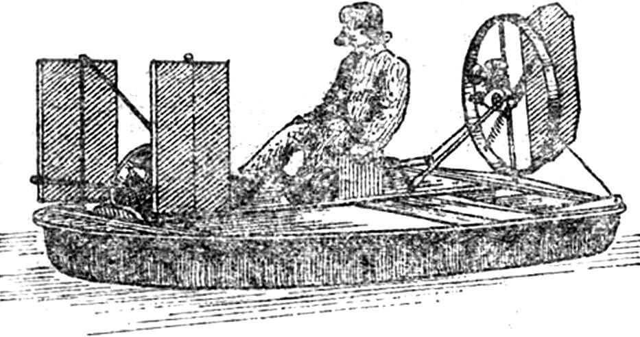
Our great compatriot K. E. Tsiolkovsky in 1927 proposed another solution: to reduce hydrodynamic resistance using a thicker air layer—an air cushion. At the same time, Professor V. I. Levkov of the Novocherkassk Polytechnic Institute confirmed the correctness of this solution with calculations and model tests. In 1935, he built experimental boats L-1 and L-5 and successfully tested them: the boats moved above the water surface, freely came ashore, and maneuvered over a plowed field. In control tests in 1937, L-5 showed a record speed for ships of 73 knots (over 133 km/h) on water.
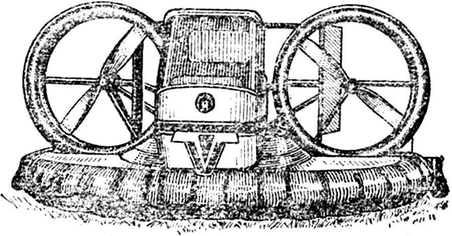
Fig. 1. Single-seat amateur amphibian “Cartair Mk 111” (Australia). Equipped with two two-stroke engines (160 cm3 each). Centrifugal fan, control—by air rudders.
The work of V. I. Levkov was continued by designers G. S. Turkin, who was the first in the world to develop a nozzle scheme apparatus and received an author’s certificate for a “cross-country wheel-less transport vehicle on an air cushion,” and V. I. Kozhekhin.
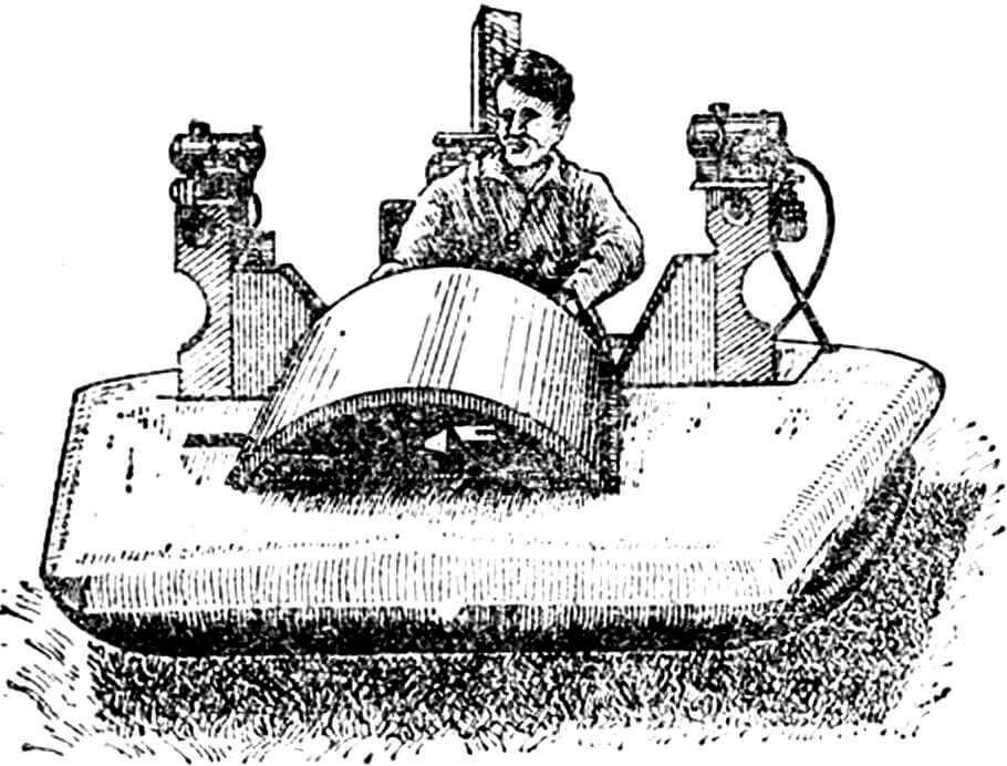
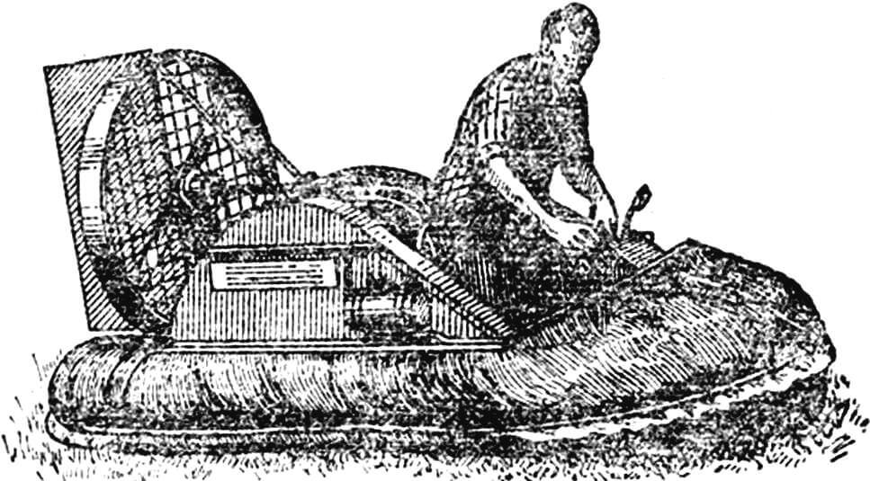
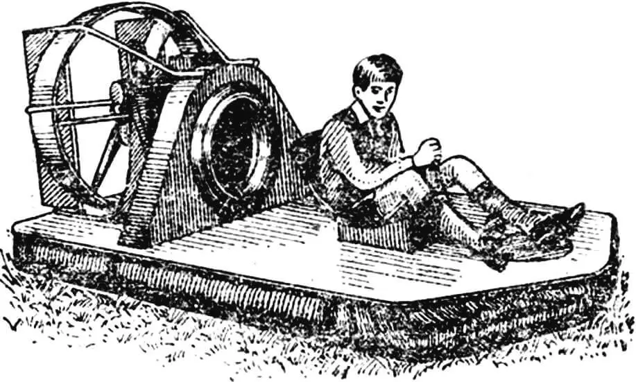
The prospects of using such vehicles attracted the attention of foreign specialists as well. Starting from the 50s, firms from England, Canada, USA, France, Japan and other countries worked on them. Many different types of machines have been created: from single- and two-seat ones (fig. 1—3) to large transport vehicles with a carrying capacity of hundreds of tons.
In our country, air cushion vehicles have already found wide practical application in the national economy. According to their purpose, they are divided into several types:
ACV — air cushion ships, used only over water. These include passenger ships “Sormovich”, “Krasnoye Sormovo” and others;
GEM — ground effect machines (cars, minibuses, motorcycles), designed for movement over water and over land in off-road conditions: over swamps, waterlogged fields, plowed land. Many such all-terrain vehicles have been created in our country. These are “Bars”, “Vikhr”, “Breeze”, “Gepard”, “Raduga”, MPI-18, SAVR-1, SAVR-2 with a capacity of 5—10 passengers and light single- and two-seat machines from Kharkov Aviation (fig. 4), Ufa Polytechnic Institutes, numerous amateur-built GEMs;
ACP — air cushion platforms, which include cargo self-propelled and non-self-propelled vehicles towed by some type of transport. The West Siberian Research Institute of Oil Industry built a whole series of such platforms with a carrying capacity of 40, 60 and even 400 tons for transporting heavy oil production equipment in off-road conditions.
It was also reported that abroad “Atlant” is being created—a nuclear-powered air cushion ship intended for transatlantic voyages. It has a displacement of 15,000 tons, a speed of 130 knots and will be able to carry 4,000 passengers and 2,000 cars.
A direction such as wheeled or tracked vehicles with aerodynamic unloading has also appeared. In off-road conditions, they activate an air cushion that removes a significant part of the vehicle’s weight. At the same time, the air pressure is regulated so that the traction force of the wheels or tracks when they engage with the ground remains sufficient to ensure movement.
A prototype of an air cushion vehicle can be an ordinary pot without a lid, turned upside down. The air pressure in it is equal to atmospheric. If air is pumped into the vehicle’s hull, the pressure will increase. According to Pascal’s law, it spreads in all directions with equal force, acting on the walls, the bottom of the vehicle, and the base on which it stands. The walls are rigidly connected to each other and cannot expand from pressure forces. But the bottom and base can. The pressure forces acting on the bottom will gradually take the weight of the vehicle upon themselves until they tear it away from the base. A gap is formed through which air will begin to escape. The blower will compensate for this consumption, and the vehicle will hang over the base—will be held on an air cushion (fig. 5).
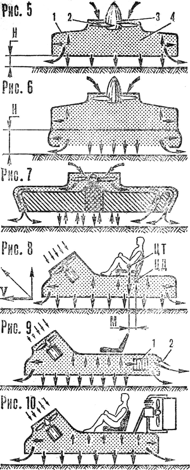
1 — hull, 2 — air propeller, 3 — engine, 4 — high pressure zone, H — hovering height.
Fig. 6. ACV scheme with flexible enclosure—skirt.
Fig. 7. Nozzle scheme of air cushion formation: left—single nozzle, right—double nozzle.
Fig. 8. Motorcycle on air cushion:
CG — center of gravity of the entire system, CP — center of pressure of the hull, M — heeling moment arm, V — horizontal component of thrust force.
Fig. 9. GEM scheme equipped with controllable windows (1) and flap (2).
Fig. 10. GEM scheme with separate drive of blower and propulsion.
The cross-country ability of such a vehicle when it moves is low, since the rigid bottom does not allow ground irregularities under itself. Cross-country ability is increased by installing a soft enclosure—a skirt—around the perimeter of the hull. The hovering height of a vehicle with a skirt at the same pressure is significantly greater (fig. 6). This is the so-called chamber scheme, which has one significant drawback—low stability. A vehicle of this design is extremely sensitive to changes in balance.
We already mentioned G. S. Turkin’s invention—a nozzle scheme vehicle. Its essence is that air from the blower is directed into a nozzle made along the entire perimeter of the bottom. This is a narrow intermittent gap oriented at some angle to the center of the machine. Exiting the nozzle, the air forms a curtain that encloses the high-pressure zone under the hull. The hovering height increases significantly. Even better are two similar parallel nozzles. Nozzle scheme vehicles are less sensitive to changes in balance.
Amateur technical enthusiasts actively use the property of small ACVs to respond sensitively to minor changes in balance for control. A small change in the position of the center of gravity (CG) relative to the center of pressure (CP) of air on the bottom is enough, and a pair of forces that heel the ACV is formed. Air flows out from under the hull unevenly—more to the side opposite to the heel, a horizontal force is formed, which is used for control.
Figure 8 shows a sketch of a single-seat motorcycle on an air cushion. The driver’s seat is made movable, on rollers. The driver uses a lever to shift the seat together with himself forward or backward, leans to the side. In this way, he moves the center of gravity, causing the motorcycle to heel and changing the speed and direction of movement. The blower on the vehicle is positioned at an angle: the oncoming air flow is used to increase pressure in the air cushion due to dynamic pressure. In addition, due to the blower’s tilt, a horizontal component of thrust force arises, which ensures forward movement.
Control is also possible thanks to the reactive force formed when air is released through the rear swiveling flap (fig. 9). Turning is done using special windows in the hull sides, which are equipped with controllable shutters or louvers. Air released through these windows creates a reactive force—the vehicle rushes in the desired direction. The shutters are usually in a closed position and open during maneuvering and braking.
No less common is a scheme with separate drive of the blower and propulsion: a pushing or pulling air propeller (fig. 10). However, it should be noted that there is some inconvenience in operating separate power plants. When starting engines with a cord or shock absorber, strict adherence to a certain sequence is necessary: first start the propulsion engine and only after it warms up and is switched to low rpm—the blower engine. When starting with an electric starter or compressed air (as on ACVs with automotive and aircraft engines), such a sequence may not be observed.
Control is by a rudder in the air flow behind the propeller. Such a control surface is effective even with a slight deflection. However, the air rudder also has a drawback: the center of pressure on it is located high. During turns, the aerodynamic force creates a significant overturning moment, the consequence of which is lateral heel. It is especially noticeable on dome scheme vehicles.
Increased stability can be achieved by dividing the internal space of the air cushion with rigid or soft partitions into separate chambers. This will prevent air flow and ensure pressure retention due to the restoring moment that arises in the chambers during heel.
And yet, the issue of controllability of air cushion vehicles is not fully resolved. The main problem here is the sail area and inertia of ACVs. A side wind easily drifts them to the side, constant energy expenditure is required to maintain course. During turns, especially at speed, air cushion vehicles, having turned, continue to move straight for some time sideways by inertia. This significantly increases the turning radius and complicates control.
Air cushion ships are in a more advantageous position, as they usually have side keels immersed in water along the sides. The keels prevent lateral air leakage, help more fully use the dynamic pressure of the oncoming flow to increase pressure in the air cushion, and create resistance during lateral drift of the ship.
GEMs do not have such keels. However, it can be assumed that installing freely rotating metal disks along their sides that engage with the ground will contribute to increased stability of vehicles during turns and when moving with a side wind. Such disks should have shock absorbers and be easily engaged with the soil when needed.
What attracts in light air cushion vehicles? First of all, the simplicity of design: there are no complex transmissions, no propulsion systems like wheels, tracks, which account for a large load and the main mass of breakdowns in operation. There are also no complex control mechanisms. At the same time, high cross-country ability and significant speed of movement are achievable on ACVs.
Amateur technical enthusiasts have designed and built many similar machines: by K. Vshivtsev from the Moscow region, A. Buyanov and his young friends from the Pioneer House of the distant Taysha station, Riga resident O. Peterson, D. Mukhin from the Saratov region (fig. 11), B. Alexandrov and Yu. Shumikhin from the Leningrad Palace of Pioneers and Schoolchildren named after A. A. Zhdanov, N. Kuraev from the Primorsky Territory. “Modelist-Konstruktor” wrote about the last two ACVs in issues 6 and 12 of 1975.
Analyzing the designs created by amateurs, one should note their simplicity, accessibility, and repeatability. It is gratifying that most vehicles were built with the active participation of schoolchildren. For them, this is an exciting and at the same time serious work, in which knowledge of many academic disciplines is actively used and deepened, and interest in technical creativity, invention, and rationalization is instilled.
I. YUVENALYEV
Recommend to read
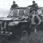 ATV “TRAMP-YUGRA”
The history of the vehicle is quite long. First began to be fit to travel on our road of "Niva-2121" - put her on the big wheel from the "Jeep". Traveled on it with a neighbor (also,... WHEELS? IN THE TWO ACCOUNTS!
The simplest method of making "shoes" for the trace of the car based on the manufacture of the hubs of the elements of the dry type batteries А343 "prima" and the like. From...
