SILENT AND SWIFT

SILENT AND SWIFTRiding on the electric chart is this — silent and swift. We got it, which is the usual standard cards. The internal combustion engine is removed and the seat moved forward by 100 mm, which allowed to install on the frame between it and the rear axle battery 6CT-132. This arrangement lowered the center of gravity and improved weight distribution on the wheels.

As the motor used is a modified starter with a capacity of 1.6 kW and a voltage of 12 V from car ZIL-130. The purpose of the revision is to improve the cooling of the starter, i.e. to create such conditions under which he worked would not be a matter of seconds, by car and tens of minutes.
 
Modernized starter inside and outside. Interior upgrade included replacement bearings ball, which resulted in a modification of the end caps. The front, which subsequently established BEARING No. 202, machined from steel (Fig. 2). (Ventilation holes can in principle have any configuration, as long as their area was the highest.)
 
Rear cover only reworked: removed the rivet brush holder and grind it on a lathe according to figure 2. Then use new rivets and insulating sleeves attached to the back cover and the brush holder carved from a steel housing for bearing No. 201.
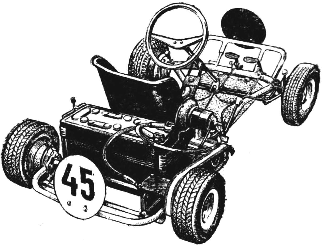
Changed and the shaft of the rotor. Squeezed it into the centers and bored through. On one end cut also the splines under the sprocket from the moped, and the other grooves with a width of 2.5 and a depth of 1 mm to increase the area of cooling.
 
Fig. 1. General view of the electric chart (the cover of the battery removed).
 
Fig. 1. General view of the electric chart (the cover of the battery removed).
 
Fig. 2. New and improved structural elements of the electric starter
 
Fig. 2. New and improved structural elements of the electric starter:
 
1 — front cover 2 — back cover. 3 — bearing housing, 4 — insulating sleeve (ebony, 4-piece), 5 — rivet (8 PCs), 6 — anchor.

 
Thus the inner modernization have prepared everything to ensure that the starter could give the maximum amount of heat generated in the work. To take it meant air, that run through the starter special fan. This was the point of exterior upgrades.
 
For cooling we used the centrifugal fan from the heater of the cab of the GAZ-51. Together with the engine attached to its clamp to the rack, welded to the starter housing (Fig. 4). The output of the fan and the casing that covers the brush, joined to a short pipe. Toggle switch fan switch placed on the steering bracket.
The starter also includes a homemade mechanical contactor (Fig. 3). The cap of insulating material with contacts, stock (his grind) and the locking washer taken from the retractor relay starter is used. The bushing in the plate up the back. In the same way secured to the bracket y, the focus of the sheath of the cable. Other parts connected with screws.
 
The spring Cup has chosen the harder — this is more reliable. Particular attention is paid to the fact that she was part of the glass with minimal clearance. Similarly, included in the spring and short the stock.
 
Fig. 3. Contactor
 
Fig. 3. Contactor
 
Fig. 3. Contactor:
 
1 — charge, 2 — bracket, 3 — axis, 4 — frame, 5 — lever, 6 — bushing, 7 — screw-limiter, 8 — rod, 9 — Cup, 10 — bracket, 11 — emphasis cable, 12 — recoil, 13 — spring, 14 — coil spring Cup, 15 — screw-limiter, 16 stock contactor, 17 — spring contactor, 18 — contactor screw, 19 — body.
 
Fig. 4. The layout of the elektroagregat
 
Fig. 4. Layout master:
 
1 — starter, 2 — drive sprocket 3 — fan motor 4 — starter housing with a nozzle, 5 — contactor, 6 — wire control contactor, 7 — bracket Assembly to the frame card.

 
Return spring to move the parts of the contactor to its original “off” position. Its bracket is attached to the insulating the cover with the two M4 screws.
 
Screws-limiters are for adjustment. They are making a clear tripping of the contactor.
 
All generator sets installed in place of the internal combustion engine and attached to the frame of the card using a bracket from the corner 45×45 mm, welded to the starter housing. The control cable contactor interlocked with the gas pedal, it’s engine and turn on.

Recommend to read

  • THE AIR — SCOUTTHE AIR — SCOUT
    The plane of distant radar detection E-1B TRACER. The idea of installing a radar plane to detect air targets first appeared in England in early 1936. But the preference nevertheless was...
  • AT THE START — “PENNANT-9”AT THE START — “PENNANT-9”
    Flying clubs Directive of the Central Committee of DOSAAF of may 25, 1979 allowed to build gliders only on the drawings approved by the technical committees of local federations of hang...