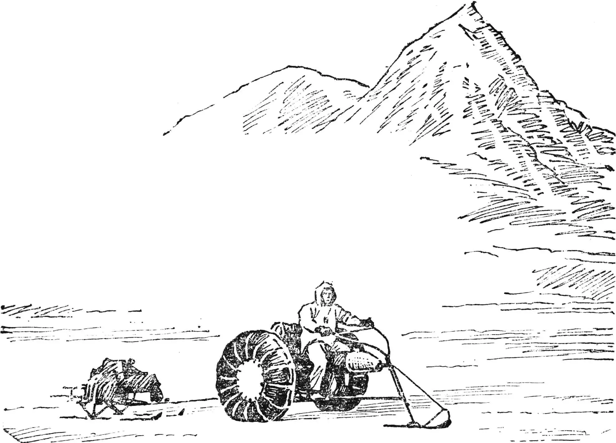
The simplicity of the “Arfa” design is probably unique. The vehicle has only six main parts: a frame with an engine, a rear axle, wheels, a ski with a steering rod, and a steering wheel. The snowmobile’s reliability and low maintenance match the very highest requirements imposed on a vehicle intended for autonomous runs across vast, uninhabited areas of the far North. The “Arfa” can be easily dismantled and transported to the start point in a truck bed or in a luggage railway car, and then assembled in about an hour and a half to set off on the journey.
The frame is made from 25X25 mm square-section tubes with a 1 mm wall thickness. Its upper and lower longerons are connected by three elements: the steering bushing, the upright, and the brace.
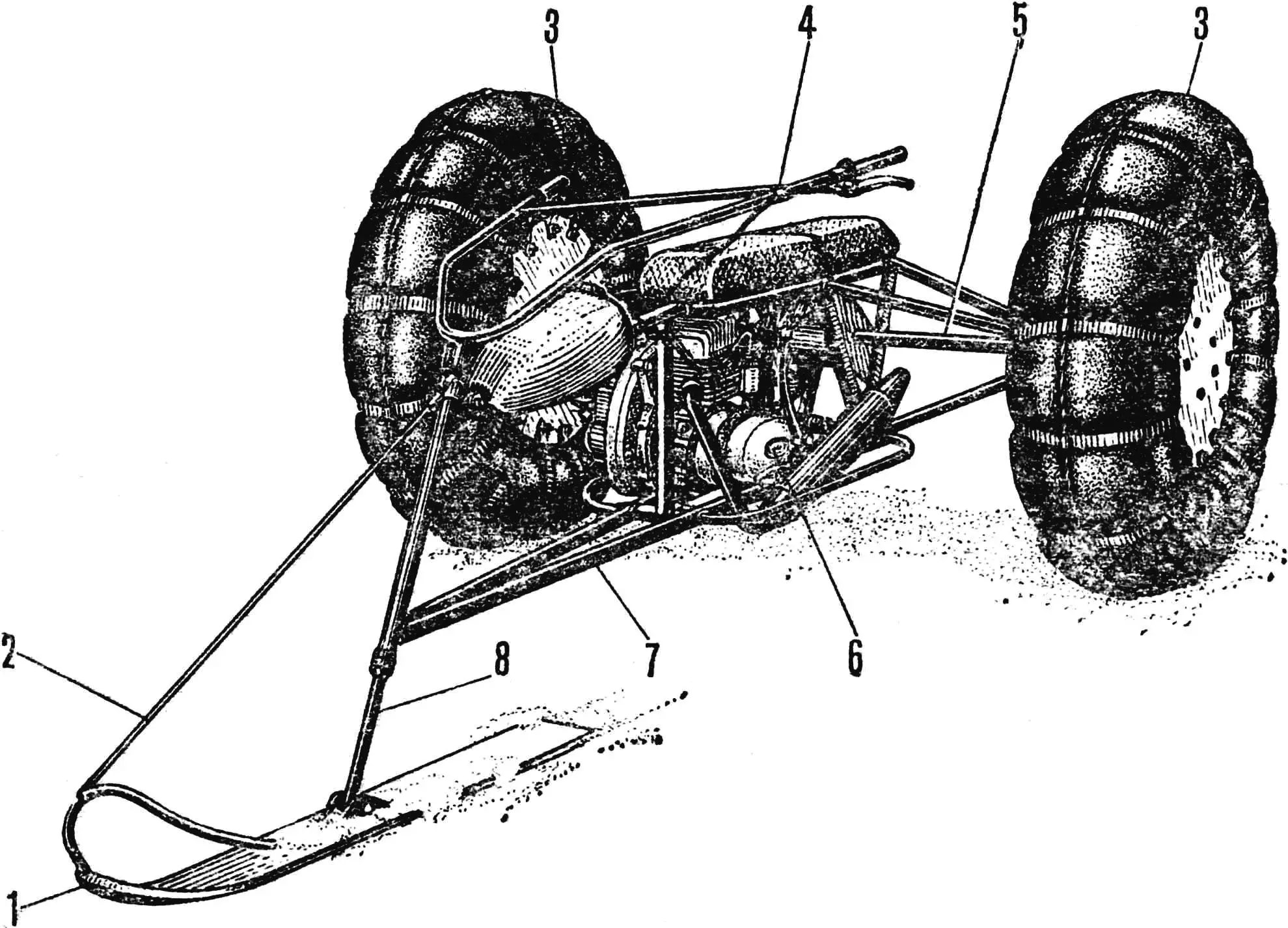
1 — ski with a shock absorber, 2 — elastic cord, 3 — low-pressure chambers, 4 — steering wheel, 5 — rear axle, 6 — engine, 7 — frame, 8 — steering rod.
The steering bushing is a steel tube Ø 32X2 mm; on its ends are fitted bearing races with bronze bushings pressed into them—plain bearings.
The upright (a section of tube with a 25X25 mm cross-section) is welded to the first strut of the lower longerons and to the location where the upper longerons connect to the longitudinal tube. Since this assembly experiences the highest impact loads, it is reinforced with two gussets.
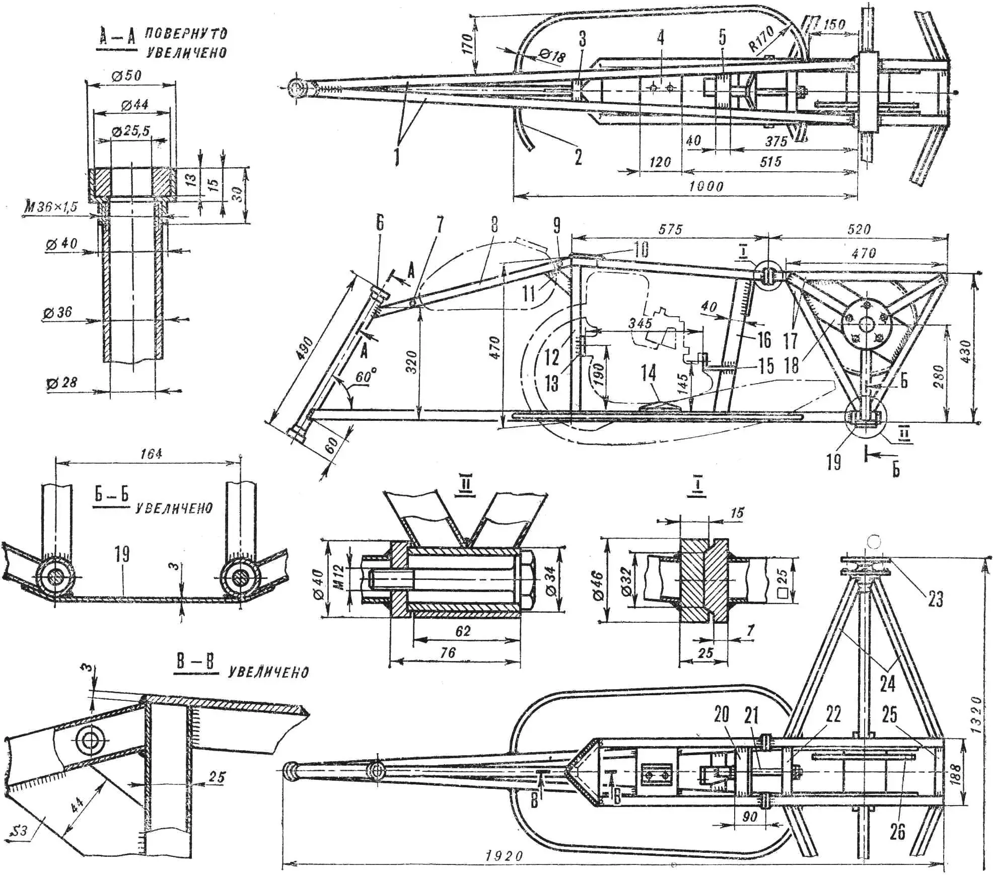
1 — lower longerons, 2 — footrest, 3 — first strut, 4 — support of the adjustable engine-mounting unit, 5 — second strut, 6 — steering bushing with plain bearings, 7, 9 — fuel tank mounting points, 8 — longitudinal tube, 10, 11 — gussets, 12 — upright, 13, 14, 15 — engine mounting units, 16 — brace, 17 — bridge pyramid base tubes, 18 — cheek plate, 19 — lower tie, 20 — transverse element, 21 — M12 bolt, 22, 25 — upper ties, 23 — half-shaft flange, 24 — pyramid ribs, 26 — axle sprocket.
The brace is made from a 40X25 mm rectangular-section tube and welded to the second strut of the lower longerons and to the transverse element of the upper part of the frame.
On the upright and brace there are a plate and an angle bracket—engine mounting units for the «T-200». The third unit is a channel with a slot for adjustment bolts, located on a 3 mm thick steel plate welded to the lower longerons.
A 20-liter fuel tank (from a Jawa motorcycle) is mounted on the longitudinal tube.
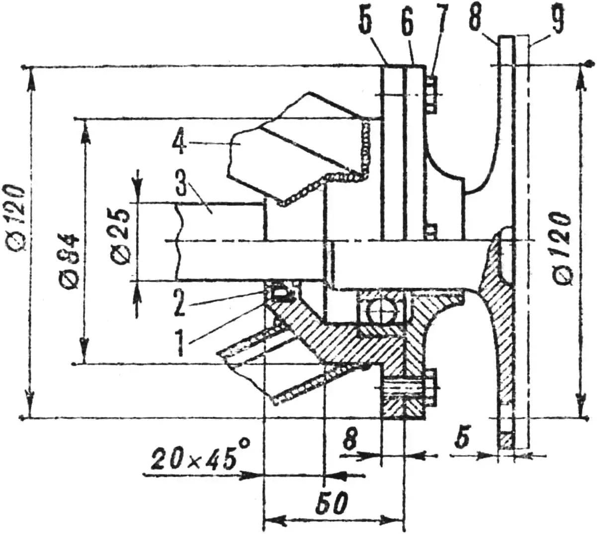
1 — bearing housing, 2 — seal for the oil seal, 3 — half-shaft, 4 — pyramid rib (25×25 mm tube), 5 — connecting flange, 6 — bearing cover, 7 — M8 screw, 8 — half-shaft flange, 9 — ground-down part of the flange.
The rear axle frame is made mainly from 25X25 mm tubes in two stages. First, the right and left pyramids are welded, and then they are connected with ties: the lower one (a 3 mm thick steel strip) and the upper ones (sections of rectangular 25X25 mm tubes).
Bearing housings for half-shafts from the Moskvich-407 car are welded into the pyramid tops, and cheek plates (3 mm thick steel strips) are welded to the bases; between them sits the Moskvich-407 differential with a homemade casing and a belt brake.
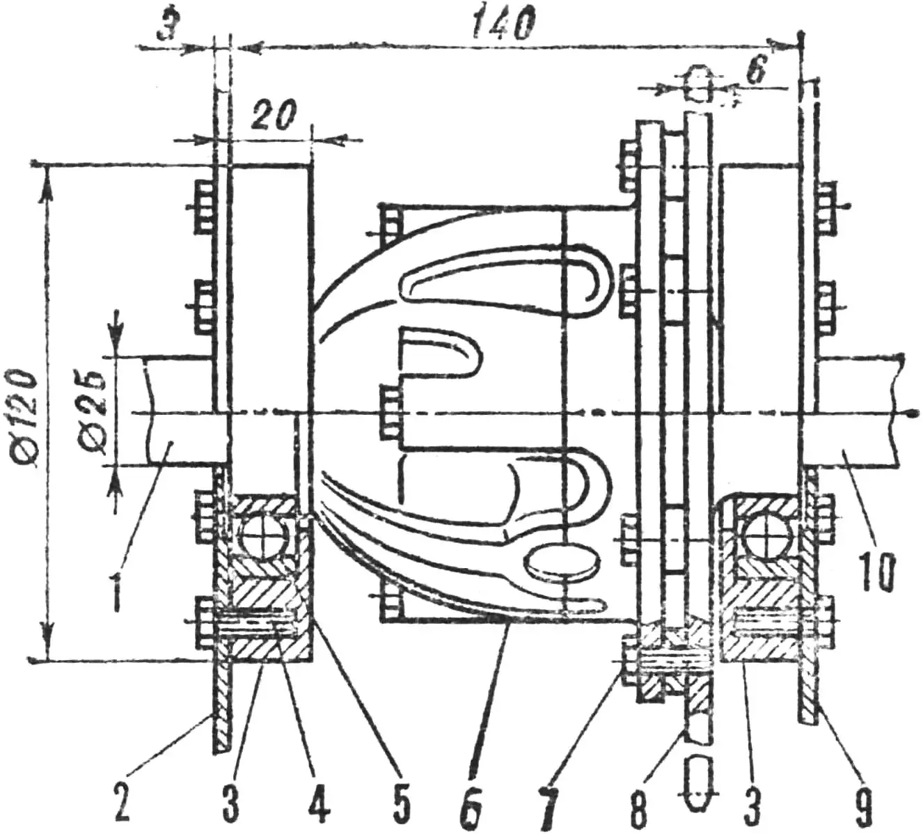
1, 10 — left and right half-shafts, 2, 9 — cheek plates, 3 — bearing housings, 4, 7 — M8 screws, 5 — bearing, 6 — differential housing, 8 — sprocket.
The differential bearings are pressed into aluminum housings bolted to the cheeks, and its driven gear is replaced by a sprocket with 72 teeth. A chain with a 15.9 mm pitch connects it to the engine’s 10-tooth sprocket. The half-shaft flanges are machined down to a 5 mm thickness.
The frame and the rear axle have four mating joints—two on the upper and two on the lower longerons—and are connected with three M12 bolts. One bolt clamps the transverse element of the frame’s upper section and the first axle tie; the other bolts clamp the lower longerons and the bushings welded into the corner of the pyramid bases.
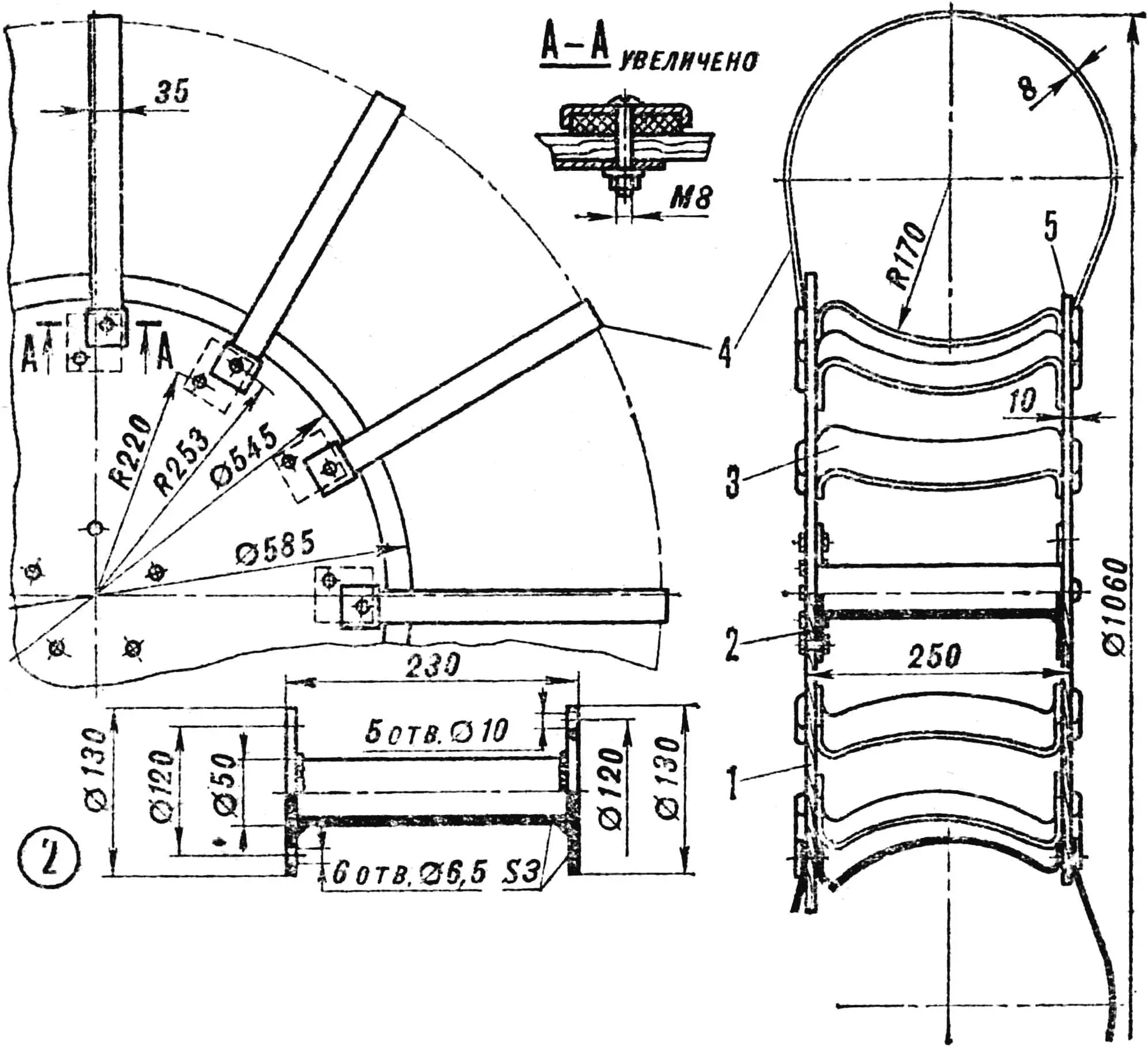
1 — outer disk, 2 — tubular axle, 3 — saddle, 4 — rubber-and-fabric belt, 5 — inner disk.
The snowmobile wheels are a combination of tubes from a trailer for the K-700 tractor and disks made from 10 mm thick plywood, steel tubular axles, and aluminum saddles. The tubes are strapped with rubber-and-fabric belts made from an 8 mm thick conveyor belt.
The outer disks are slightly larger in diameter than the inner ones, because when driving along slopes the snowmobile driver, trying to keep his body vertical, leans toward the wheel that rides higher on the slope and adds load to it. On a wheel with the smaller disk, the tube would flip out behind it and get “chewed up,” since the air pressure in it is only 0.3—0.4 kgf/cm2. Here this does not happen. The wheels are attached to the half-shaft flanges with five M10 bolts.
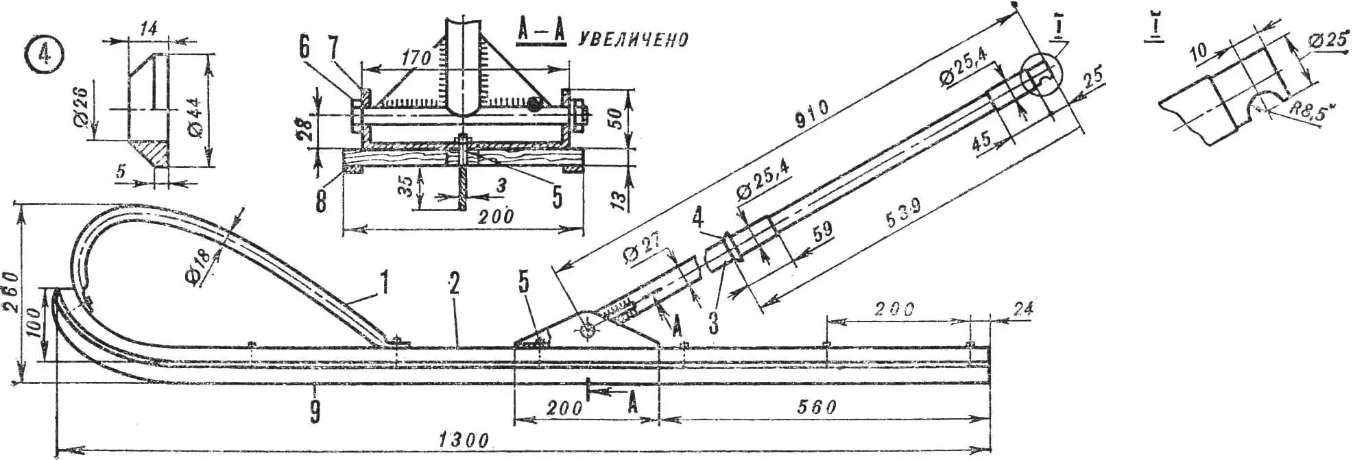
1 — shock-absorbing handle, 2 — ski, 3 — steering rod, 4 — thrust washer, 5 — stud, 6 — axle, 7 — bracket, 8 — edge, 9 — axial runner.
The ski is bent from laminated plywood and equipped with an axial runner, edges, a shock absorber, and a steering rod.
The runner is made from a 3 mm thick steel strip; it is attached to the ski with M3 studs welded to it at a 200 mm spacing. The edges that protect the plywood from abrasion are screwed on with screws.
The shock absorber (a Ø 18X1.5 mm tube) performs two functions: it prevents the ski tip from breaking when hitting an obstacle, and when carrying the snowmobile it serves as a handle. An elastic cord is also attached to it, which constantly keeps the ski in an elevated position.
The steering rod is machined from a steel rod, has a flat for the steering wheel, journals for plain bearings, a thrust washer, and at the end an axle.
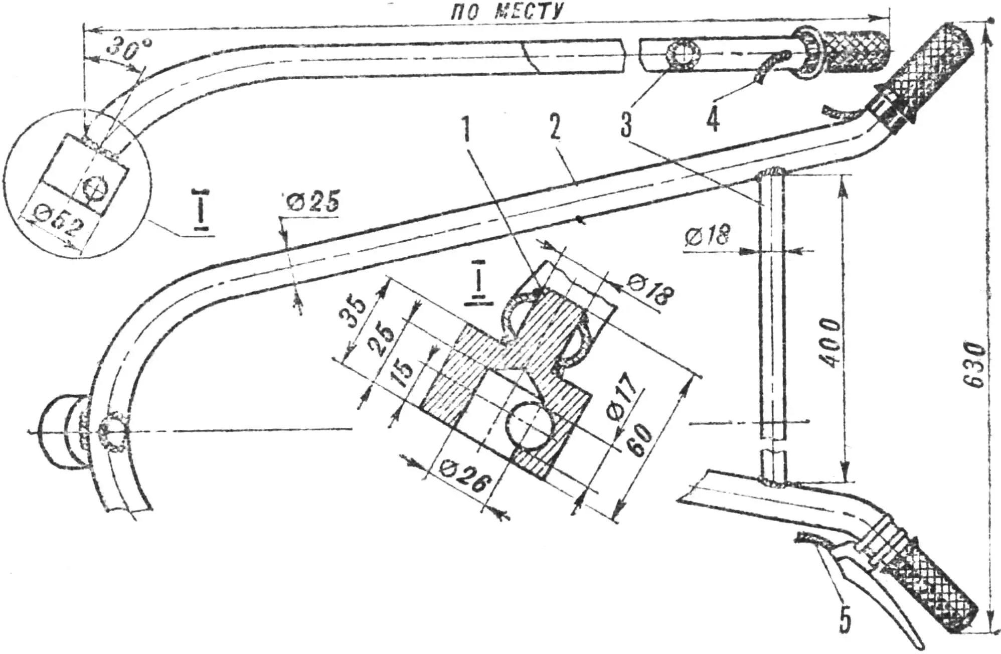
1 — bushing, 2 — tube, 3 — spacer, 4 — throttle cable, 5 — clutch cable.
The handlebar is bent from a steel tube. At its center, a bushing with two holes—one blind and one through—is welded at a 30° angle. The first hole receives the top of the steering rod with its flat, and the second hole receives the locking pin. The two halves of the handlebar are connected for rigidity with a spreader made from a Ø 18X1.5 mm tube, and fitted with control grips from a scooter: throttle sector on the right, and a clutch lever on the left.
The rider sits on a seat mounted on the upper longerons above the engine.
«М-К» 5’84, A. TIMCHENKO
Recommend to read
 THE MACHINE “HEARD”…
Most of the machines and mechanisms used in industry, agriculture and the service sector, by themselves, unfortunately, still not working. These mechanisms have to enable, disable,...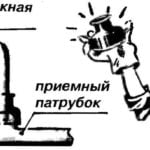 HOW TO SEAL THE DRAIN
Offer house masters a simple way to seal the junction of the different diameter of the exhaust pipe from the siphon kitchen sinks and suction bend discharge pipe. This is the best suited...
