
 The hovercraft is. Building a vehicle that could move on both land and water, was preceded by a familiarity with the history of the discovery and the creation of original amphibious machines, air cushion (WUA), the study of their fundamental devices, comparison of various designs and patterns. To this end, I visited a lot of Internet sites enthusiasts and creators of WUAs (including foreign), met with some of them in person.
In the end, the prototype was conceived boats took the English “Hovercraft” (“the flying ship”—so in the UK called APE), built and tested by local enthusiasts. Our most interesting domestic machines of this type are mostly created for law enforcement agencies, and in recent years — for commercial purposes, had large size, and therefore is not well suited to Amateur production.
My machine on air pillow (I call it “Aerodzhip”)—triple: the pilot and passengers are located at the T-shaped diagram, as in tricycle: the pilot in front in the middle and the passengers behind, next to, one another. The single-engine machine, with multiple air flow, which in its annular channel slightly below its center has a special panel.
Boat-WUA consists of three main parts: – rotor installation with the transmission, fiberglass body and the “skirt” is a flexible surround the lower part of the body—that is to say, “cushion” of air cushion.
Case “Aerodzhip”. He’s a double: fiberglass, consists of inner and outer shells.
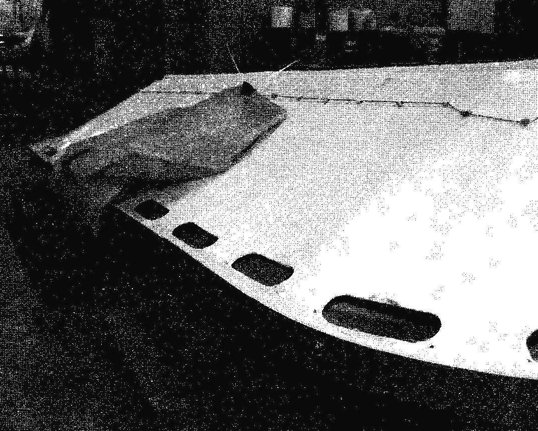
The outer sheath has a relatively simple configuration is only inclined (50° from the horizontal) side without bottom—flat almost across the entire width and slightly curved in the upper part. The nose part is rounded, and the back has the appearance of a sloping transom. In the upper part of the perimeter of the outer shell cut oblong holes, the grooves, and the bottom of the outside of the fixed eye-bolts covering sheath of the cable for attachment thereto of lower parts of the segments.
“Aerodzhip”:
1 segment (dense fabric); 2 — mooring duck (3 PCs); 3 — wind visor 4 — side fastening strap segments; 5 — handle (2 PCs); 6 — fencing of the propeller; 7 — annulus; 8 —the rudder (2); 9 — the lever handlebars; 10 — hatch access to fuel tank and battery; 11 — pilot’s seat; 12 — passenger sofa; 13 — engine; 14 — the engine; 15 — the outer sheath; 16 — filler (foam); 17 — inner shell; 18 — dividing plate; 19 — propeller; 20 — bushing of the propeller; 21 — drive toothed belt; 22 — knot for fastening the lower part of the segment
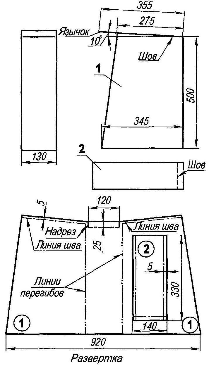
The theoretical drawing of the hull:
1 — internal cover; 2 — outer shell
Inner shell configuration is more difficult than the outside because it has almost all the elements in a small vessel (say, a boat or boats); the side, bottom, curved pensiri, a small deck in the nose (not only the top of the transom in the stern)—in this case made as a single part. Besides, in the middle of the cockpit along it to the bottom and glued separately formed tunnel with a jar under the driver’s seat, it houses the fuel tank and battery, and routed the cable throttle and shift control with rudders.
Aft of the inner shell is arranged in a kind of Ute, a raised and open in front. It serves as the basis of the annular channel for the air screw, and deck-jumper—separator air flow, part of which (support stream) is sent to the mine hole and the other part—to create the propulsive thrust.
All the elements of the case: the inner and outer shell, the tunnel and the annular channel—wileyways the matrix of the glass Mat thickness of about 2 mm on a polyester resin. Of course, these resins are inferior to vinyl ester and epoxy for adhesion, filtration rate, shrinkage, and emission of hazardous substances when dry, but has an undeniable advantage in price—they are much cheaper, which is important. For those who intend to use such the resin, remember that the place of work, should have good ventilation and a temperature of at least 22°C.
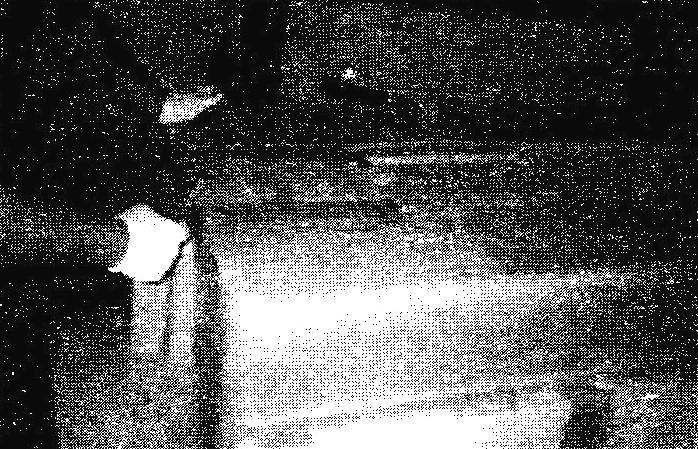
The aft portion of the inner shell (bottom up)
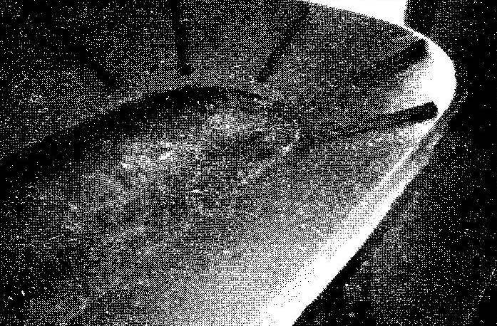
The forward part of the outer shell
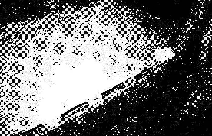
Assembly of the inner and outer shells (in the up position bottom)
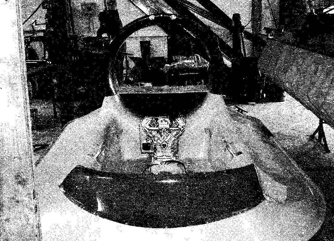
Mounting the engine aft of the cockpit. A horizontal shelf in the annular channel of the air propeller of the separation panel
The attachment of the segments to the housing
The matrix was made in advance by the master model of the same on the same made glass Mat, polyester resin, only the thickness of their walls was bigger and was 7-8 mm (shells of body about 4 mm). Before vikla-hell elements with the working surface of the matrix was carefully removed all of Cherepovetsky and a bully, and she was covered three times diluted in turpentine wax and polished. After that, the surface spray (or roller) was applied a thin layer (0.5 mm) and gelcoat (colored lacquer) is selected yellow.
After drying has begun the process of veclachi shell on the following technology. First, using a roller wax matrix surface and the side of the glass Mat with smaller pores promazyvaetsya with resin, and then the Mat is placed on the matrix and rolled up until all the air is removed from under the layer (if necessary, you can make a small slot in the Mat). In the same way fit and subsequent layers made glass Mat to the desired thickness (4-5 mm), installation where needed, embedded parts (metal and wood). Excess flaps on the edges are cropped when Vileika “in the wet”.
It is recommended for the manufacture of the hull to use 2-3 layers of glass Mat and bottoms—up to 4 layers. Thus it is necessary to glue an additional all the corners and places of screwing fasteners.
After curing, the resin sheath is easily removed from the matrix and processed: grind smooth edges, cut grooves, drilled holes.
To ensure the flooding of the “Aerodzhip” to the inner shell glued pieces of foam (for example, furniture), leaving free only the channels for the passage of air around the perimeter. Pieces of foam glued together with resin, to the inner shell attached strips of glass Mat, also smeared with resin.
After manufacturing separately the outer and inner shells they dock, are held together by clamps and screws, and then attached (glued) around the perimeter strips coated with polyester resin of the glass Mat with a width of 40-50 mm, which was manufactured by ourselves shell.
After that, the case is left up to the complete polymerization of the resin.
A day to the upper junction of the shells around the perimeter is attached by means of rivets dural strip 30×2 mm cross-section, by mounting it vertically (on it fixed the tabs on the segments). To the bottom of glued wooden rails dimensions 1500x90x20 mm (length x width x height) at a distance of 160 mm from the edge. On top of the rails is glued to one layer of glass Mat. Similarly, only from the inside of the shell, aft of the cockpit, is arranged the base of a wooden plate under the engine.
Scheme of transmission propeller installation:
1 —output shaft of the engine; 2—a leading gear wheel; 3 —a gear belt; 4—driven sprocket; 5 —nut; 6 distance sleeve; 7—bearing; 8—axis; 9—hub; 10—the bearing; 11—distance sleeve; 12—bearing; 13—propeller
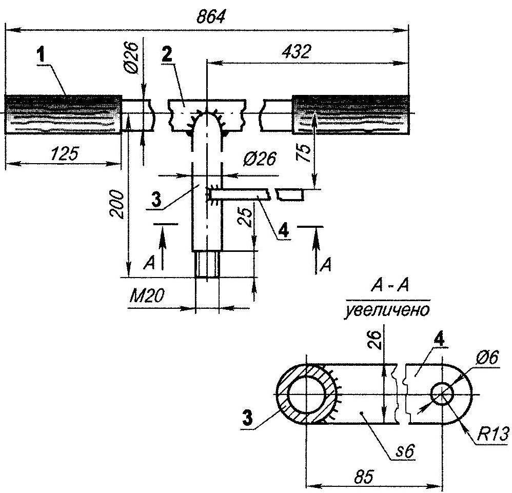
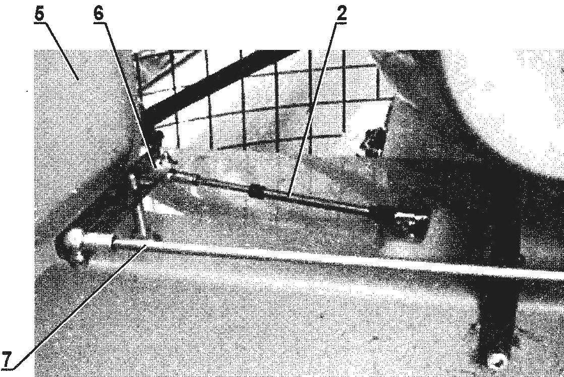
Steering column:
1—crank; 2—duplici arm; 3—strut; 4—fry (see photo)
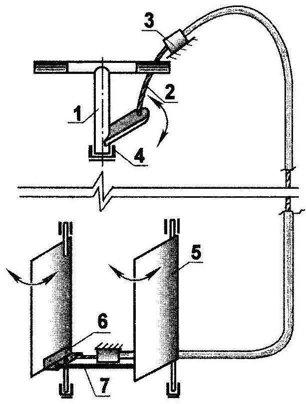
Steering control scheme:
1—steering column; 2—a Bowden wire, 3—knot attaching the braid to the body (2); 4—the bearing (5 PCs); 5—tie-bar (2 PCs); 6—duplici lever bracket (2 PCs); 7—connecting rod steering panels (see photo)
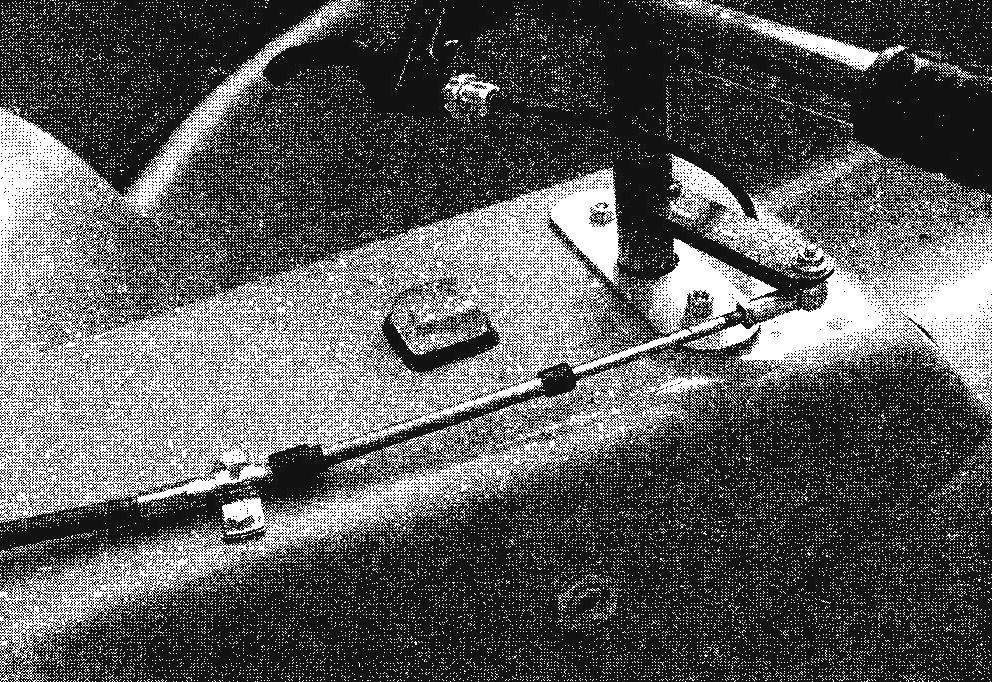
The wheel — motor type. Downstairs at the front — fry with Budenovsky cable. On the left handle throttle lever
The left panel of the rudder
The flexible segment of the fence:
1 — walls; 2 — cover with pull tab
It should be noted that the same technology which made the outer and inner membranes, wileyways and smaller elements: the inner and outer shell of the diffuser, turning the handlebars, gas tank, engine cover, petroupoli, the tunnel and the driver’s seat. Those who are just starting to work with fiberglass, I recommend to prepare a production boat with these small elements. Total weight of GRP housing together with the diffuser and rudders around 80 kg.
Of course, the manufacture of such housings can be charged and specialists—firms that produce fiberglass boats. Fortunately in Russia there are many of them, and the costs will be comparable. However, in the process of self-production will be able to get the necessary experience and the ability to continue to model and create different elements and structures made of fiberglass.
Rotor installation. It includes the engine, propeller and transmission, the transmission from the first to the second torque.
The engine used BRIGGS & STATTION, produced in Japan under American license: 2-cylinder, V-type, four-stroke, with a power of 31 HP at 3600 rpm. Its guaranteed lifespan is 600 thousand hours. Running the electric starter, from the battery, and the spark plug from the magneto.
The motor is installed on the bottom of the case “Aerodzhip”, and the axis of the hub of the propeller is attached with both ends on brackets at the center of the diffuser, elevated above the body. The transfer of torque from the engine output shaft to the wheel hub is a toothed belt. Driven and drive pulleys, and the belt is toothed.
Although the weight of the engine is not so large (about 56 kg), but its location on the bottom significantly lowers the center of gravity of the boat, which positively affects the stability and maneuverability of the machine, especially like this — “vozdukhoplavatel”.
The exhaust tailpipe is displayed in the lower air flow.
Rather than Japanese can be used and suitable domestic engines, such as snowmobiles “Buran”, “Lynx” and others. By the way, for single or double WUAs are fine motors of an output less—about 22 HP
The propeller—shestilopastnye, with a fixed step (installed on the land angle of attack) of the blades.
An integral part of propeller installation should include the annular channel of the propeller, although its base (lower sector) is integral with the inner shell of the housing. Annular channel, as the body is also a compound made up of the outer and inner shells. Just at the place where the lower part it is joined with the upper, constructed of fiberglass panel separation: it separates the air flow created by the propeller (and the walls of the lower sector, on the contrary, it connects along the chord).
The engine located at the transom in the cockpit (back seat passengers), open top fiberglass cowl, and propeller, in addition to the diffuser,—and a wire grating in front.
Soft elastic fence “Aerodzhip” (skirt) consists of separate, but equal segments are cut and sewn from dense lightweight fabric. It is desirable that the fabric was waterproof, was not hardened in the cold and does not leak air. I used the material Vinyplan in Finland, but it’s perfect Patriotic fabric type percale. The pattern segment is simple, and you can even sew it by hand.
Each segment is attached to the body in the following way. Reed said side vertical bar, with an overlap of 1.5 cm; it is the tongue of a neighboring segment, and both of them in place, overlapping fixed on a special bracket clamp type “crocodile”, only without the teeth. And so around the perimeter of the “Aerodzhip”. For reliability you can still put a clip and in the middle of the tongue. Two same the bottom corner of the segment with the nylon clamps are suspended freely on a rope, grasping the lower part of the outer shell of the housing.
This composite design of the skirt allows you to replace a failed segment, which will require 5-10 minutes. The place to say that the design is workable in case of failure of up to 7% of segments. All of them placed the skirt up to 60 pieces.
The principle of motion “Aerodzhip” next. After starting the engine and idling the device remains in place. When you increase in speed the propeller starts to drive a more powerful stream of air. Part of his (large) creates the propulsive force and provides the boat moving forward. The other part of the flow goes under the dividing panel into the side ducts of the body (the space between the shells until the bow), and further through the holes-slots in the outer sheath is evenly supplied to the segments. This flow simultaneously with the beginning of the movement creates an air cushion under the bottom, lifting the apparatus above an underlying surface (be it soil, snow or water) a few inches.
Turn “Aerodzhip” are two rudders, deflecting the “progressive” flow of air aside. Rudders is carried out from duplicera arm of a steering column of a motorcycle type, via a Bowden cable running along the starboard side between the shells to one of the rudders. The other wheel is connected to the first rigid rod.
On the left arm duplicera lever fixed lever and throttle control of the carburettor (analogue throttle).
To operate the hovercraft, you must register it in the local state inspection on small size vessels (GIMS) and get a ship’s ticket. To get the same certificate of control more to go and training for the management of the small boat.
However, these courses still far not everywhere there are instructors for piloting vehicles on an air cushion. Therefore, each pilot has to master the management of WUAs on their own, literally bit by bit gaining relevant experience.
Technical data “Aerodzhip”
Overall dimensions, mm:
length……………………………………………3450
shirima…………………………………………2400
height………………………………………….1380
The power of the engine. HP……………….31
Weight, kg……………………………………..150
Gruzopodemnostju, kg…………………….220
Fuel capacity, l…………………………..12
Fuel consumption, l/h……………………….6
Overcoming obstacles:
ascent, hail………………………………..20
wave, m………………………………………0,5
Cruising speed km/h:
at will………………………………………..50
on the ground……………………………………..54
on the ice………………………………………..60
M. YAGUBOV
Recommend to read
 THE BICYCLE WINCH IS PLOUGHING
Readers of "M-K" have long been familiar with the enthusiast of homemade soil cultivation equipment, amateur designer from Nizhny Tagil, Grigory Ivanovich ODEGOV. He was the one who...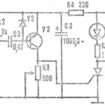 THE TIMER CONTROLS THE SOUND
The device, whose scheme is published in the journal "Popular electronics" (USA), produces a positive pulse when a sound (for example, firing of the gun) reaches the microphone B1 (see...
