
 With age the skeletal system, particularly the spine, is exposed to specific diseases. Begin to affect migrated younger overload, sports and work injuries. But at the same time and the habit of walking and by bike turns into a necessity. Thank you as with minimal cost to improve a simple road bike, making it more comfortable and “softer”. And I think I have successfully solved the problem of depreciation.
 To invite the readers of the journal “modelist-Konstruktor” technical solutions I was able to significantly “off” shocks on the body and hands from the roughness of the road.
First, I added an extra podprugin saddle on his normal road bike type “Perm” (Fig. 1).
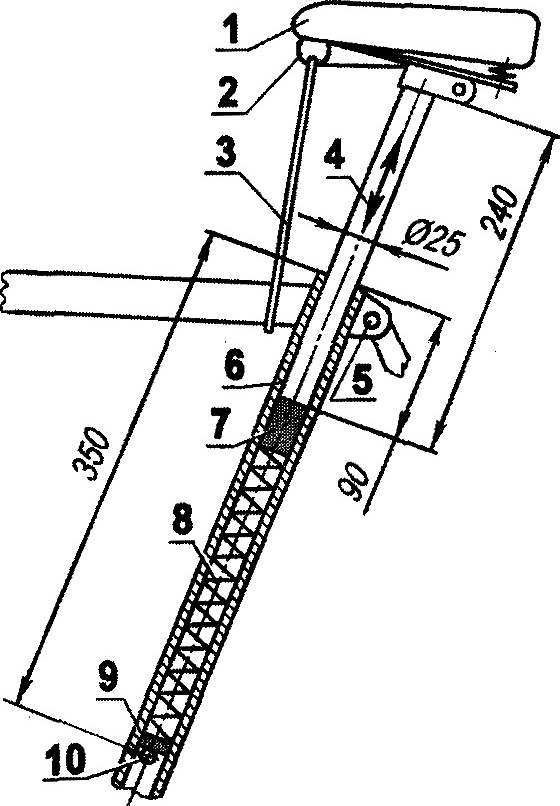
Fig. 1. Additionally, spring-loaded saddle:
1—a regular pillow of the saddle; 2—normal spring; 3—restrictive lock; 4—seat front (of the bike “salute”); 5—standard mounting bolt seatpost racks; 6—seat tubes frame; 7—tube; 8—compression spring; 9—bearing washer; 10—reference pin.
This was replaced with a regular seatpost rack on a similar item from a Bicycle “Salyut” — it is longer and a little thinner; “saltovsky” stand with a weakened mounting bolt is free to slide in the seat tube of the frame.
In the seat tube of the frame is placed a compression spring, with her on the pin inserted in the drilled in the pipe hole and the washer. On top of the spring placed in the tube. Its diameter is the same as the outer diameters of the spring and the seat stand, and she freely goes in the pipe. The height of the tube is selected depending on the spring force and weight of the cyclist. Finding the right spring was not so easy. In the end, used hard door normally compressed spring. But it stretched her “elastic limit,” making it normally stretched, and cut by the chisel to the desired length.
To spring so the saddle does not pop up when pushing up, the course has restricted flexible cable — durable thin rope.
Another technical solution for the suspension steering. Looking ahead, I will say that it made me think about making the original an additional manual drive, and this, in turn, gave rise to the replacement of the drive sprocket of the drive wheel on a more detail — driven pulley. But about all under the order.
Considering the options of cushioning the front of the bike, have found a simple solution — just podrastaet the wheel. Decided to make the wheel of two parallel tubes, the upper of which would be spring-loaded and could move around the stands rails in the vertical plane. This design is suddenly “turned” into original and simple additional hand drive bike. Figure 2 is a perspective view of this actuator.
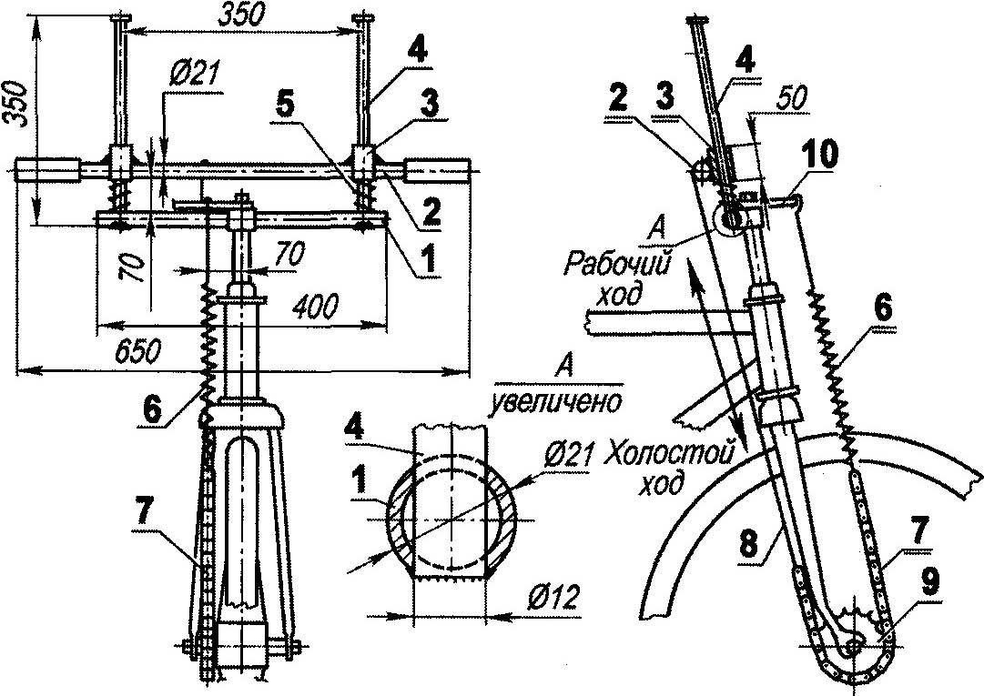
Fig. 2. Suspension steering — additional hand drive bike:
1 — prop (tube Ø 21); 2—steering (tube Ø 21); 3—sleeve (tube Ø 21, 2); 4—guiding strut (tube Ø 12, 2); 5—a spring normally decompressed (2); 6—spring is normally compressed; 7—drive chain; 8—thrust (wire Ø 3); 9—bushing the wheels with the drive sprocket (rear wheel road bike, modified); 10—bracket.
Instead of steering in carrying out established base — steel tube with a diameter of 21 mm. it is pre-drilled two holes with a diameter of 12 mm, are inserted and welded to the support rails in the rack. Stand wearing shock-absorbing compression springs and bushings with an inner diameter slightly larger than the diameter of the struts. The bushings welded on the wheel.
In the front the plug is inserted the rear wheel from another bike. From the bushing of the wheel removed the brake cones to ensure free return rotation of the drive sprocket. Using the asterisk deployed cut the drive chain with a length of 500 mm. One end is hard wire traction wheel, and the other through a weak return spring with bracket, mounted on the front fork.
Pressing on the pedal, the cyclist pulls the wheel up and over the traction and chain drives the front wheel. When the leg reaches the bottom of the “dead zone”, it quickly returns the steering wheel to its original position (down) and repeats the cycle with the other leg.
I think no need to explain that the spring loaded wheel is useful, and manual drive.
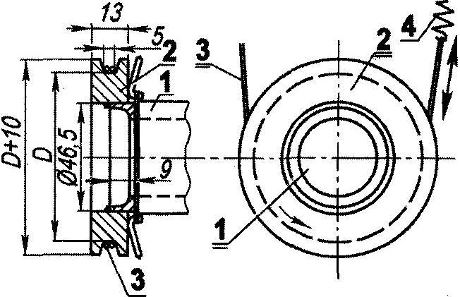
Fig. 3. Drive pulley:
1—sleeve rear wheel (modified); 2—pulley (steel); 3—flexible steel cable (Ø 2,5); 4—return normally compressed spring.
Here, during the production of a manual drive, came up with the idea to replace the drive sprocket, a pulley, and instead thrust and chain flexible steel cable, pulley slung across one or two of his round, which was done (Fig. 3). The result is positive, the drive works. Note: the roughness of the working surface of the pulley is only good. And again. The diameter of the pulley, equal to 71 mm, corresponds to the sprocket with 19 teeth, and D = 88 mm with 24 teeth.
Vladimir GAVRILOV, the item of Inozemtsevo, Stavropol Krai
Recommend to read
 THE ANTENNA… HIGH-SPEED MANUFACTURING
Once, while on vacation with an overnight stay in a tent on a wooded Bank of the river, found an annoyance: a portable TV operating off the car battery, bad was shown on the set of the... THE HOUSE WILL BE WARMER
Twenty years I live in a house built once with their hands. Of course, then was folded up and the furnace, which three years later was covered with ceramic tiles with dimensions of...
