Over the two centuries since the invention of the bike any ideas arose equipping it with a variety of engines: internal combustion, electrical, flywheel, and even sails. However, the muscular drive of the vehicle remains the most acceptable, profitable, distinguishing it from other machines because the movement it promotes physical development of a person. The only question is how rational, depending on road conditions, rider to distribute his power.
And the current bike is quite perfect design. But innovators continue to look for inquisitive and open it up additional reserves. And not without success. The proof of the next publication (previous, see the “Modeller-designer” № 10’97, 5’2000, 6’01) with the new developments of the inventor, V. M. Gavrilov from the village of Inozemtsevo area of Zheleznovodsk in Stavropol region.
MULTI-SPEED ROAD BUILDER
Road bike is simple and reliable. He has a trouble-free foot brake, which is important when driving off-road, but no gear changes, as, for example, a multi-speed Bicycle of type “Tourist”, so necessary when riding cross-country (hills and ravines) area. However, the Tourist has only the hand brake, in my opinion, has neither the smoothness nor the reliability nor durability, and it is much more expensive.
Is it possible to combine the advantages of both types of bikes? Turns out that if you think about it, in part by installing at the road instead of regular driven sprocket block of three rigidly attached (welded) through the remote wire ring coaxially stars.
The first (small) sprocket with 18 teeth, staff. It is tempered, so it is for subsequent welding to the block should be let go, that is warm up in the fire (in the fire or over a gas burner) until red and cooling in air.
The second and third stars, respectively, with the number Sublim 24 and 28 improvised. They are made of sheet steel with a thickness of 2.3 mm on the following technology. On a small sheet of drawing paper compass is a circle (for the second sprocket with a diameter of 97 mm). Then the paper is laid on a soft cardboard (or several layers of Newspapers). On the sheet is part of a Bicycle chain (24 level) so that the centers of the axes of its links is located approximately on the drawn circle, and the distance between the axes of the first and the last link was equal to the chain pitch — 12,7 mm. This part of the circuit carefully covered with a piece of plywood sheet and, through him, hand pressed against the paper. On paper fingerprints axes. Then the steel sheet is glued to the mold and the metal in the middle of the printed dots from the axes, nutriveda centers and drilled 24 holes with a diameter of 8.5 mm. Further from sheet steel with a chisel or a hacksaw cut the billet sprocket. It remains only on the pattern to lay out, gently grind on the sandpaper and a file each tooth and also make the center hole with a diameter of 51 mm.
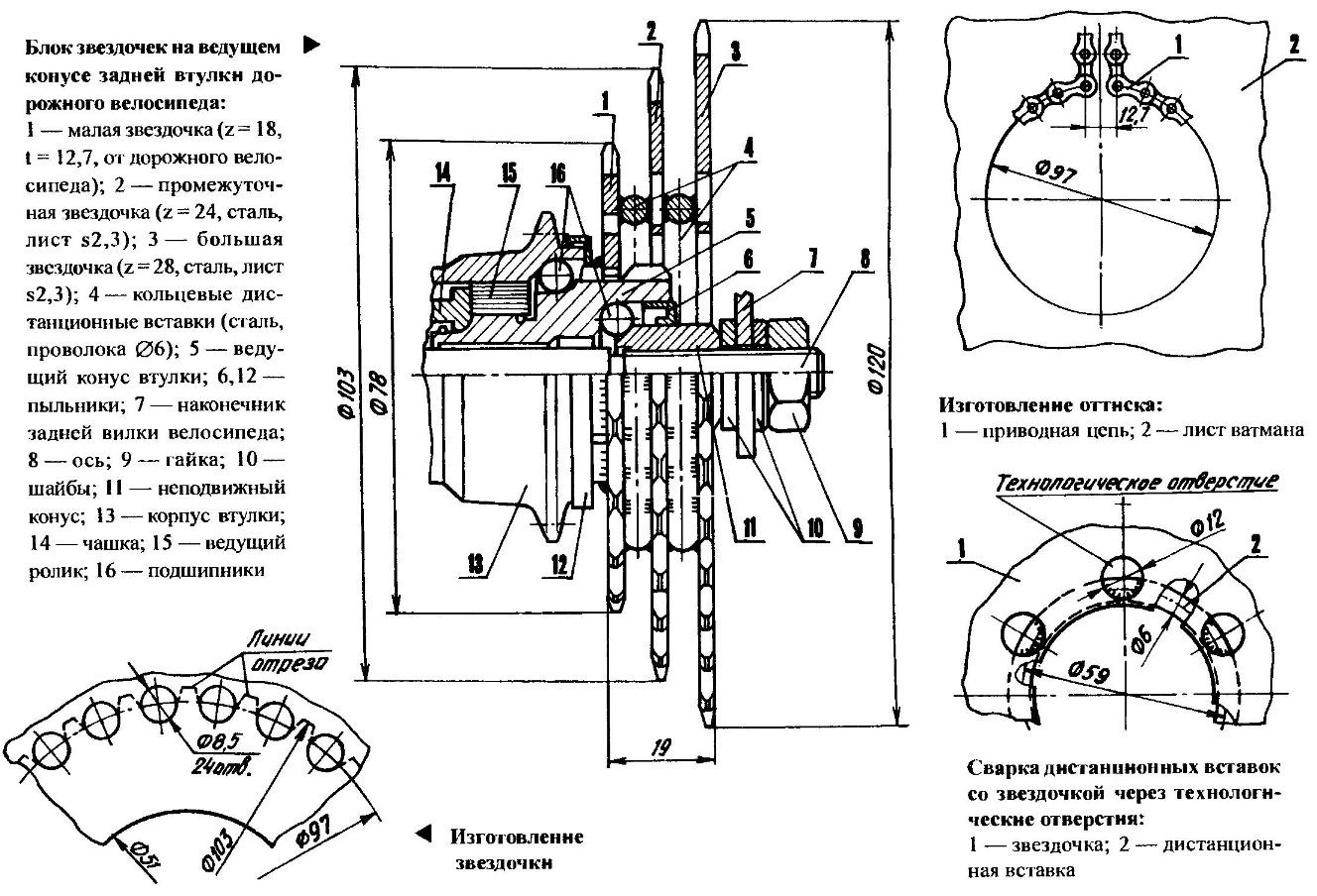
In the same way and made the third star, only the diameter of the circle on the graph paper was equal to 112 mm and it was placed at the 28 links in the chain. In place of this asterisk can be installed and ready from the old children’s bike — it has the same number of teeth with the same pitch. Just before welding it too must be let go.
Two ring remote inserts with an internal diameter of 52 mm bent from 6 mm steel wire. Before joining sprocket in a single unit, for ease and reliability of welding them to the rings in a homemade sprockets drilled several technological holes with a diameter of 12 mm. then, ensuring the alignment of the sprockets to prevent the runout of the gear rims, ring and star are sequentially welded to each other by points that are evenly distributed around the circumference.
Made a block of asterisks is planted on the outer part of the lead cone rear hub of the Bicycle, and the regular (smaller) sprocket welded to it in a circle a reliable continuous weld. You could just fix the unit native spring ring, as usual, but there is no guarantee that the thermally released slots small sprocket will withstand the increased load.
For welding the lead cone is released from the bearing rollers and heat is released similar to the asterisk. Re-tempering of the part, as shown by operation, can not do.
Axis length enough to secure the driving wheel with a block of sprockets in the rear fork of the Bicycle.
And here is a simple and reliable self-made gear shift I, as he tried to construct could not. So installed on your road Builder standard mechanism from the old bike Tourist, rigidly securing it with bolt M10 directly in the hole of the frame. Lever gear shift was placed under the seat. Those who have no such switch speeds, I suggest you prepare two pieces of chain with locks on both ends: the first five units, the second nine. Then before the next trip even at home, you can lengthen (or shorten) the chain and put it on the required sprocket, depending on the intended nature of the route, speed, and their physical form. For example, if you have to go light on the highway, it selects a smaller sprocket and shorter chain (without inserts). When it is necessary to overcome the way on a country road, even with a load in the circuit is inserted a long stretch for a lot of stars.
AUTOMATIC TRANSMISSION
As you know, to change the torque to a driving wheel of a Bicycle depending on the road conditions (uphill — downhill, the ground — highway) use two main ways: either use the rear driven sprockets of different diameters by successively transferring them to the chain or change the length of the rods.
If the first method has long been tested and implemented in a production model, then on the second do not. However, the simplicity of the latter suggests its potential popularity in the future.
The proposed design allows you to automatically adjust the length of the connecting rod and hence torque, that is, to switch the speed depending on the “resistance” of the track.
It should be noted that the left connecting rod right node the same. And although the left chain is missing, but the asterisk is necessary here for fastening the parts. In a regular pedal rod is screwed in finger, made of heat-released end of the carriage connecting rod shaft, a finger tapped М14х1,25 (right).
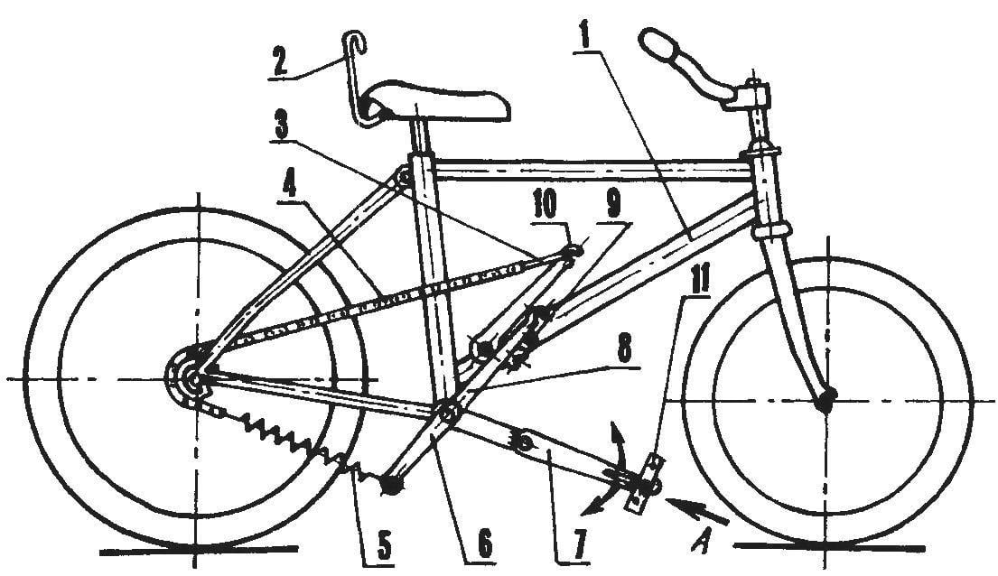
Multi-stage automatic transmission:
1 — drive sprocket; 2 — staff rod; 3 — megatonic finger (from the end of the carriage shaft); 4 — additional rod; 5 — a pedal; 6 — strap (steel, strip 30×3); 7 — drive chain; 8 — latch; 9 — spring; І0 — the axis of the spring; 11 — bushing; 12 — washer
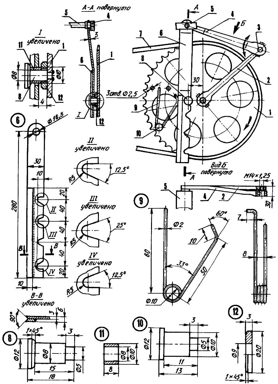
On the finger pin with a slight backlash fixed additional rod so that it allows the rods to pivot relative to each other at a slight angle. And at the end of the additional rod is installed the pedal, the distance from which to the axis of rotation of the drive sprocket may be changed and adjusted by means of steel plates with grooves.
Strap is freely mounted on the axis pedals and relies grooves on the sprocket is welded to a cylindrical lock Assembly in a bushing between the flange and washer. Strap is preloaded to the axis of the /-shaped spring, which is also freely mounted on its axis. One end of the spring is bent and included in one of the three holes of 2.5 mm diameter drilled in the sprocket. The axle is made according to the type of lock and the same way with it mounted on the sprocket. The other end of the spring is also slightly bent inwards and inserted into the groove formed by the cut 45° edges of the strap and welded thereto lining, which ensures constant contact of the striker and the bar axis at different positions. Additional rod is slightly curved so that its end with the pedal included in the regular plane of the connecting rod and the strap was parallel to the sprocket (the upper end is also slightly bent).
Final angular dimensions of the slots are determined by the strap and trimmed with a file at run-depending on the parameters of the spring and the leg power of the cyclist. The holes in the sprocket at the end of the spring allows you to edit the effort. After adjusting grooves details (strap welded to it a plate) are hardened by heating on a flame to light red color and cooled in the engine oil.
The principle of the device is as follows. The position shown in the figure, corresponds to the minimum torque as the pedal is closest to the axis of rotation of the sprocket, which is optimal during fast driving on level highway. If you increase the slope of the road increases and efforts on the bar, resulting beveled edge of the first sliding groove, with the bushing latch, overcoming the resistance of the spring, and the striker jumps the neighboring groove. This leads to an increase of the radius of rotation of the pedals and torque. With increasing resistance of the track plank is gradually moving into the next groove, and so on until the last, whose lower side (like the top of the first) perpendicular to the axis of the strap, which limits its further movement.
To reduce the torque and the length of the working part of the strap (decreasing the rise of the road) a cyclist in the upper “dead point”, stopping the pedaling, force presses the pedal and this causes a similar return straps to the next slot.
The design is simple, reliable and effective, as shown by the test, and provides nearly double the difference in torque and therefore “speeds”. Pedal when it is separated far enough from the ground, and foot from the front wheel. The rear fork of the frame can slightly adjust the hammer so that the rods did not touch her.
Given the size of the device belong to an adult bike with a closed triangular frame. It is obvious that it can be installed on any bike with a foot brake.
IT IS POSSIBLE AND WITHOUT ASTERISK
Introducing drive for a Bicycle, successfully tested by me in practice — a fundamentally new mechanism. Its action is not based on the rotation of the connecting rod, and their oscillatory motion. What gives? First, work both legs simultaneously, which greatly increases the power. Second, it is possible to significantly extend the pedal cranks, which will also increase torque. Thirdly, it is easier to shift gears, which is important when travelling uphill.
To use this drive of the rear hub road bike brake drum lessons for free reverse rotation of the small driven sprocket and the bike is equipped with manual brakes. In addition, the simultaneous lifting of both legs requires more developed muscles of the thighs and abdomen (but that will come with time).
The drive consists of connecting rods (let’s call them so): speed, tension and two pedal — one for each leg rigidly interconnected into a single structure. Pedal connecting rod length 240 mm is combined, welded each of the two normal (the first of them cropped). That they don’t touch on turns the front wheel, the last taken of smaller diameter from the bike “salute” (the wheel from “Kama”), high Speed connecting rod is also combined. It is the same as the pedal, is welded lap joint of two ordinary in such a way that the distance between their ends is 50 mm. the ends of the rods are ground off on the sandpaper, forming two hooks. For them, clinging mesh, made of 3 mm steel wire, connected with the upper end of the chain. To the same rod, 50 mm below the welded one hook. It allows for a wider range to adjust the torque. Loop to change the speed of the movement being transferred by the cyclist on the right hook with your right hand. Speed the connecting rod is fixed to a shaft of the carriage, as usual, wedge pin, and to him in this place under an angle of 70° is welded on the right pedal connecting rod. For reliability and rigidity can be further connected with the rod, forming with them a triangle (not shown). To pedal the rod is welded to another connecting rod — tension is directed opposite to the speed. On its end there is mounted a spring connected with the chain and gives it the tension at the engagement of the loop with any hook. The lower limit of the stroke of the connecting rod unit is limited to the core focus fixed on the bottom (strut) pipe frame.
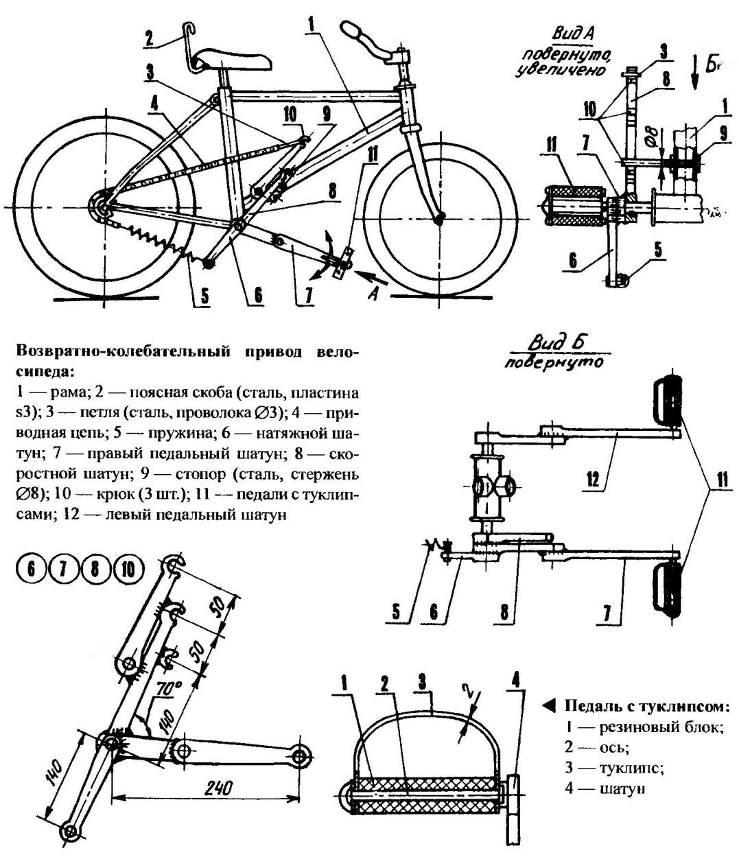
Technique drive with such a drive requires additional devices. In order to raise the pedal, you should at least one of them to supply tulipson, which stop should be easy to get and even easier to display. It can be cut from sheet metal, plastic, or thick leather for Shoe sizes. After disassembling the pedal and knocking through-bolts from the rubber wedges, the last cut on the thickness of tulips and installing it, re-assemble the pedal.
When both legs are pushing the pedals down, then body mass may not be sufficient to provide the maximum force. So for Cycling with such a drive you need a sturdy belt to which the back of one end of said steel bracket and the second end when the drive is put under the bottom of the seat. When you stop the bracket can be easily lifted out of engagement with the seat. It is made from a strip of 3mm steel, and its length is chosen individually.
Before the trip, the cyclist, tightening the belt hanging on the back of the belt clip, enters the foot (e.g. left) to toeclips pedals, lowered into position when the speed crankset brought to a stop. Rebounding from the road other foot, sits in the saddle and leaning on the steering wheel, sharply raises feet and presses on the pedals. If the rise in the road is significant and requires such efforts that the hull begins to rise above the saddle, the cyclist with one hand, gets the lower end of the bracket under the saddle. This will provide an additional connection to the bike and allow the legs to develop maximum force, although this constant engagement of the brace with a saddle will not interfere with a normal trip.
Recommend to read
 STAR ANNIVERSARY PARADE
Vertical takeoff aircraft Yak-36. In 1960, Yakovlev made a proposal to the government to develop the aircraft vertical takeoff and landing (VTOL) Yak-104. The project involved the use of... TRAILER-BEDROOM
The main problems faced by the travelling enthusiast, perhaps the problem overnight, especially in the fall. Solve it in different ways. Some rely on the place in the camping, others...