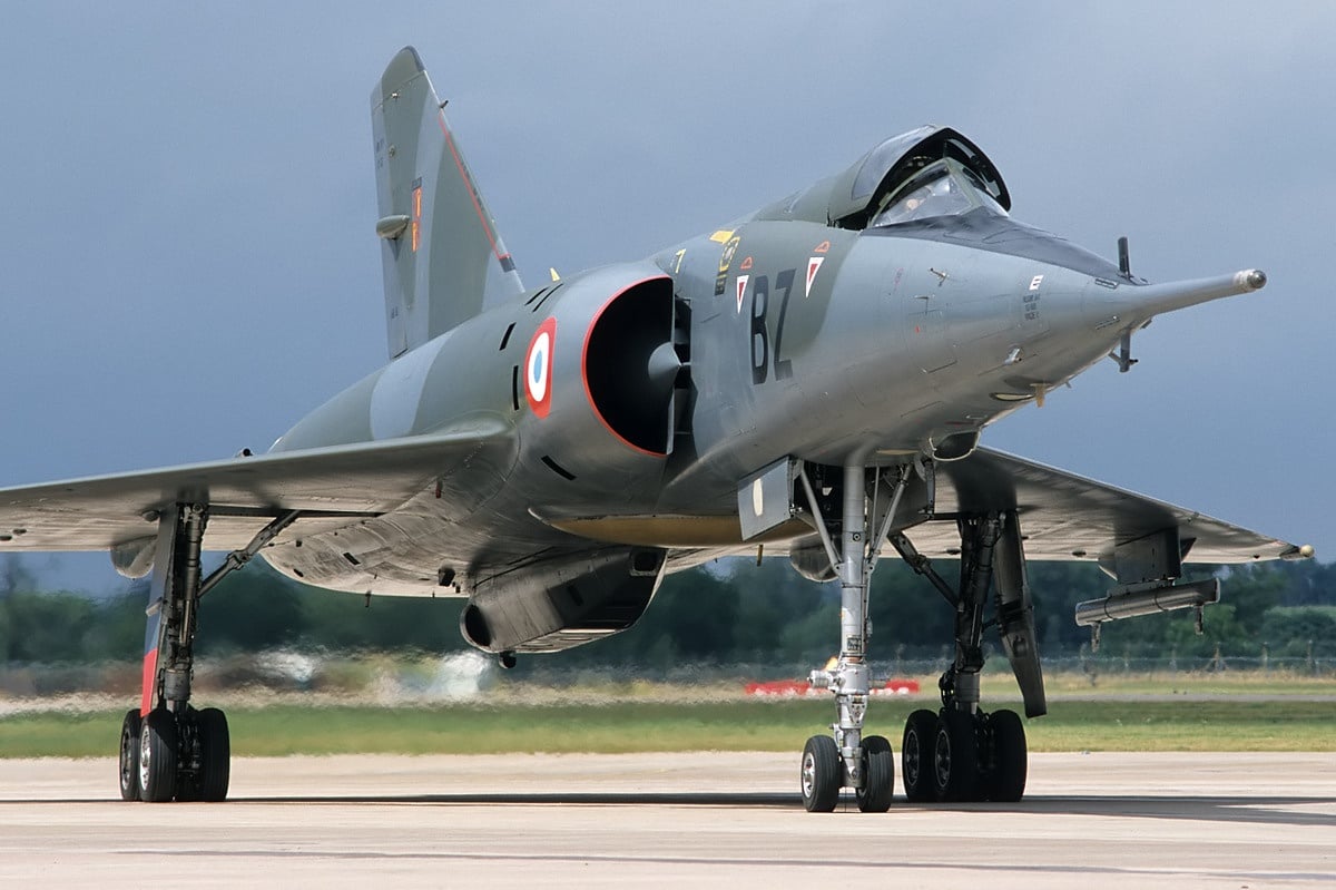
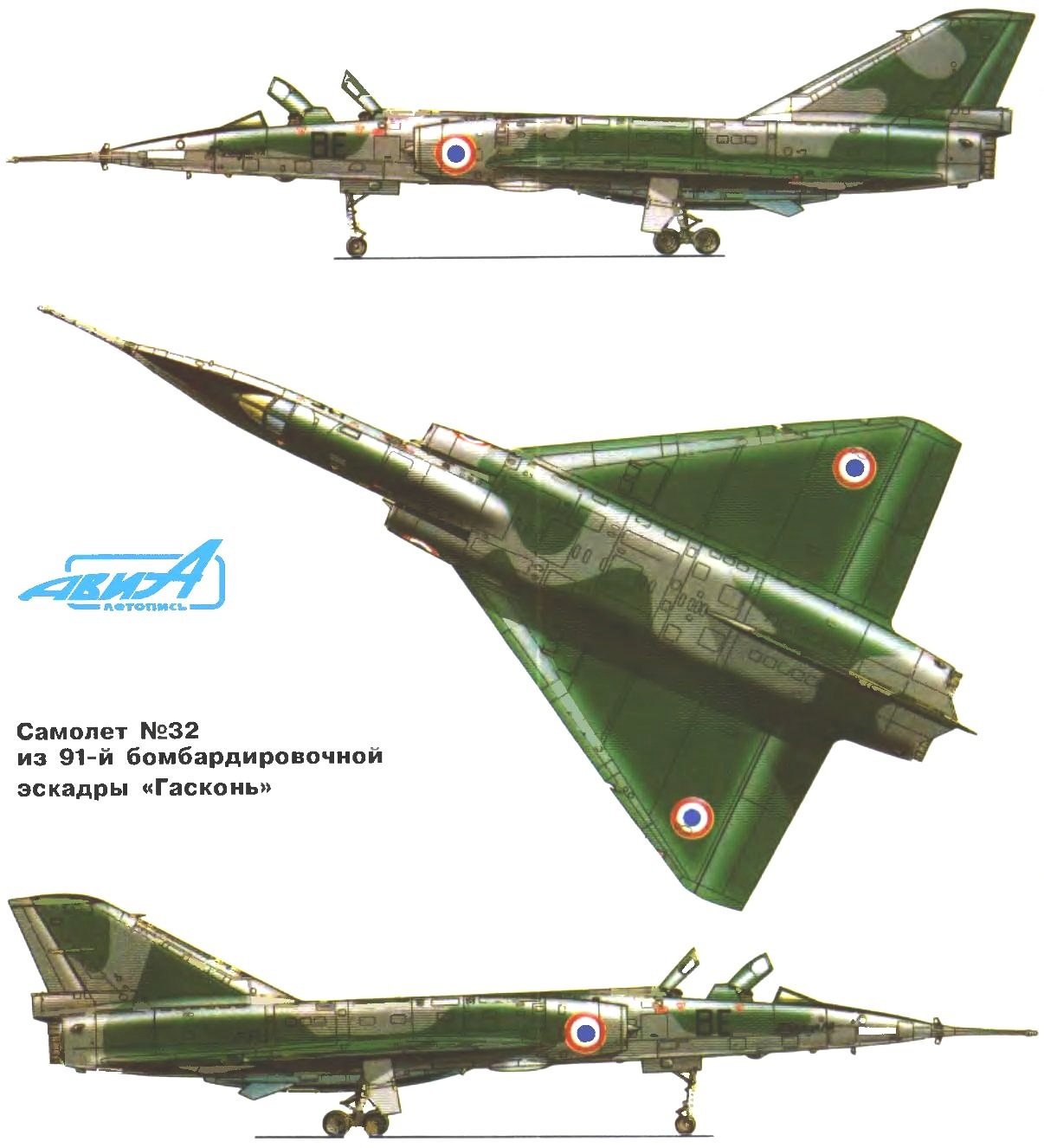
 Strategic bomber Dassault MIRAGE IVA. To raise the country’s prestige after the defeat in Vietnam and the independence of the defense capability of the United States, France officially announced in 1954, about the beginning of the creation of nuclear weapons. Two years were spent on the development of relevant scientific and production infrastructure, and in April 1956 the Ministry of defence held a competition for the best project of the strategic bomber carrier of the future French atomic bomb. The military wanted to obtain a jet with a range of 2,000 km, supersonic speed and payload of 3,000 kg.
The struggle for order has joined the firm Sud-West, Nord Aviation and Avions Marcel Dassault. The first two projects did not differ in depth study and was rather sketchy, so the competition was won by firm Dassault.
The development of bomber the Dassault firm is headed by J. Chabrier. The basis of the idea of the new aircraft he put the aerodynamics and design of twin-engine aircraft single-engine Mirage II and Mirage III (work on the latter were under construction prototype). If you compare designed the bomber with the Mirage III, to meet the requirements of the military, the geometric dimensions of the fighter had to increase more than 1.3 times, with the wing area increased almost twice. The estimated takeoff weight reached 25 tons.
To lift the plane into the air required a more powerful propulsion from two turbojet engines both SNECMA with afterburner and thrust 6120 kg each. Radius with two drop tanks was to be 1,500 km. According to the calculations of a group of engineers J. Chabrier, half of this distance the car can fly at a speed corresponding to the number M = 1,7…2, and the other with transonic speed (M = 1).
In April 1957, the government ordered the firm one of Dassault aircraft for flight testing. After the first phase, the aircraft wanted to use for testing of the first atomic bomb above the ground Reggan in Algeria, whose construction was in full swing.
In early April 1959 in the test center Milan Vilares a demonstration of the first prototype of the French strategic nuclear bomber, the MIRAGE IV 01. Pointed, silver, polished to a mirror Shine plating, it made a tremendous impression; without a doubt, it was the most elegant “flying triangle” from the Mirage family of aircraft. The length of the bomber was 20 to 420 mm, the wingspan is 11 280 m.
First flight of the machine took place on 17 July 1959 in the cockpit was test pilot R. Hlavani. The second time the MIRAGE IV 01 was lifted in the air known pilot R. began. He actually spent the entire test cycle of the aircraft. During the eighth flight of the MIRAGE IV 01 easily broke the sound barrier. In the 33rd flight was achieved a maximum design speed of flight, corresponding to the number M = 2, at a height of 18 000 m. Factory tests ended at the 53rd flight. MIRAGE IV 01 was transferred to a military test center, Istres air force. The flight took place at the speed of 1800 km/h and took 18 minutes.
The first aircraft on 19 September 1960 set a world’s speed record on the basis of 1000 km — 1820 km/h MIRAGE IV 01 was flying 33 minutes without external fuel tanks fully fueled, double-clicking on the closed route length of 500 km, the center of which was the Orly airport. At the same time, the aircraft set a speed record on the closed route length of 500 km — 1972 km/h. This figure has exceeded the speed record, owned by American F-4 Fantom 14 km/h, however this achievement was not formally recorded. The landing was carried out at the speed of 320 km/h, the length of the path with a brake parachute was 700 m. After the flight, the pilot stated that he could reach higher speeds if not for the limitations associated with the maximum air temperature at the inlet to the compressor of the engine. On serial aircraft was planned to install engines with a thrust of 7000 kg with steel compressor blades that have removed all restrictions.
The fate of the plane could develop in two directions. The first is set to “01” arms and the corresponding on-Board equipment and run it in the series. This version is called the MIRAGE IVA. The second is continued research to build a better aircraft with the designation MIRAGE IVB with a takeoff weight of around 50 tonnes and a range of 2500 km. In the case of the adoption of the second option building a full bomber could only be ended by 1961. Considering these terms to be unacceptable, the government adopted a already built plane.
It should be noted that this decision was taken without the influence of the then existing doctrines about the role of missile weapons. Over the planet have already appeared artificial satellites of the USSR and the USA, on the open ground starts was on duty, ballistic missiles, and at sea, held sea trials of the nuclear submarine “George Washington” with Polaris missiles.
The French did not want to fall behind, superpowers and launched its missile program, believing that the bombers will stay in service is not more than ten years, until the end of the 60-ies, and then will be replaced by ballistic missiles, ground and sea-based. Therefore, you shouldn’t have to spend time and money to develop new aircraft. And 9 September 1959, the firm Avions Marcel Dassault-ordered three machines in variant of the MIRAGE IVA.
Constructed a prototype MIRAGE IV 02, soaring 12 October 1961, differed from the first plane. He had some large, some form of keel and it had everything needed to install on-Board equipment and weapons. The atomic bomb of the type “A” (AN-11 ) with a capacity of 60 Kt, which concluded in a streamlined armored container with stabilizers, suspended in a semi-recessed position between the engines. Very experienced bomb on 13 February 1960 in Algeria, it was the first test of a French nuclear weapons. The third aircraft flew in June 1962 and the fourth, on 23 January 1963.
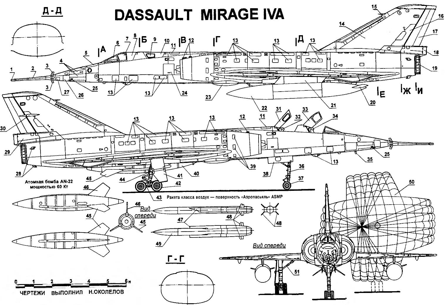
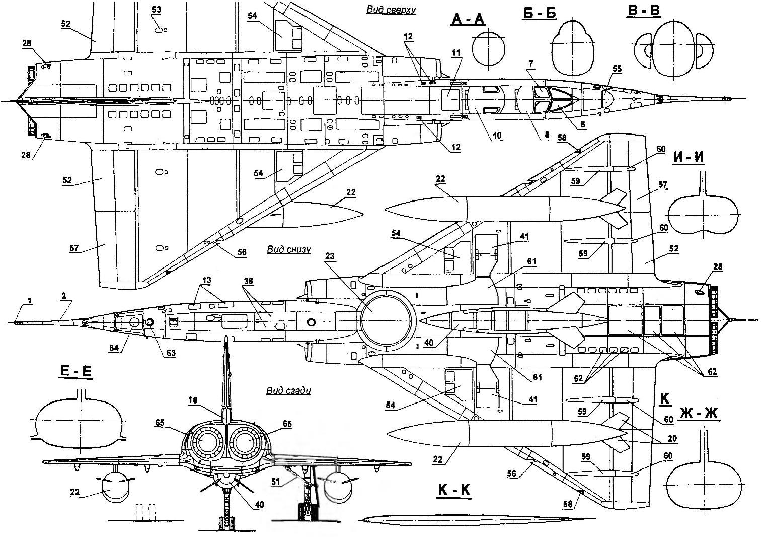
Strategic bomber MIRAGE IVA:
1 — filling the system host in-flight refueling; 2 — fuel rod; 3 — blades of the wind vane pointer to a slip angle; 4 — outlets of the compartments of electrical equipment; 5 — compartment electronic equipment; 6 — canopy of canopy pilot; 7 — cockpit glass cockpit; 8 — discharged, the canopy pilot; 9 — glass canopy of the Navigator; 10 — reset the lamp of a cabin of the Navigator; 11 — hatch access to the equipment compartment navigation and bombing system; 12 — slit air outlet from the air-conditioning system and heat exchanger; 13 — maintenance access holes; 14—Kiel; 15 — HPH redundant systems; 16 — hatch access to the cylinders control the rudder; 17 — rudder; 18 — fold compartment of the braking parachute; 19 — adjustable nozzle engine; 20— stabilizer outboard fuel tank (PTB); 21 — wing pylon; 22 — PTB; 23 — surveillance radars; 24 — operating the flap blocks the hydraulic actuators of the control system; 25 — LDPE primary system; 26 — lower maintenance hatch compartment of electrical equipment; 27— the hatch of the battery compartment; 28 — intakes system pressurization of the fuel tanks; a 29—compartment brake parachute; 30—fairing rocking of the rudder; 31 — a lamp of a cabin of the Navigator in the open position; 32 — ejection seat for the Navigator; 33 — the canopy pilot in the open position; 34 — ejection seat pilot, 35 — landing light (in released position); 36 — a nose landing gear; 37 — wheel nose landing gear; 38—fold niche cleaning the nose landing gear; 39 — antisurge fold; 40 — nuclear bomb AN-22 with a capacity of 60 Kt; 41 —shield niche of cleaning the main landing gear; 42 — wheel truck main landing gear, the 43—truck main landing gear; 44 — the main landing gear; 45 — stabilizers bomb AN-22; 46 Kil bomb AN-22; 47 — intake air missiles; 48 — steering surface; 49 combat head part; 50 — dome cruciform brake parachute; 51 — strut main landing gear; 52 — internal sections of the elevons; 53 — operating flap servo elevon; 54 — shields air brakes; 55 — retractable headlight illumination filling unit; 56— aerodynamic tooth; 57 — the outer section of the elevons; 58 — ANO; 59 — fairings pull elevons; 60 — fairings rocking elevons; 61 — fold niches of the cleaning of trucks of the main landing gear; 62 maintenance hatches of the engine; 63 — landing light (in the retracted position); 64— the window of the camera; 65 — afterburner engines
The 01 aircraft, in fact the aerodynamic prototype of MIRAGE IV was used mainly for crew training; in 1963, the MIRAGE IV crashed. Plane 02 intended for testing bombing using models. On the plane 03 has passed the test of the avionics: it established a panoramic radar “Cyrano 2” similar to the locator with anti-submarine aircraft Breguet 1050, and English Doppler radar “Marconi” AD2300, produced in France under license. After testing it was used for testing in-flight refueling from a U.S. air tankers KC-135F.
In 1963, France bought from the United States 14 air tankers especially for flights of strategic bombers, the Mirage; a refueling range of their flight reached 4000 km. and there was a French refueling system, which was shown at the 24th Paris air show at Bourget in the spring of 1961. Then refueled Mirage of suspended aircraft container “Water”. MIRAGE IVA 04 was fully consistent with the serial configuration of the aircraft. It was the engine “Atar 9K” with a thrust in afterburner 7000 kg.
When all systems have been established, has begun mass production of strategic bombers, the MIRAGE IVA. State order consisted of 50 machines. The first dozen expected by the end of 1963. During 1964 it was planned to build another 22 aircraft. The termination of the supply was planned for 1965.
Built aircraft were passed into service of a new type of air force long-range aviation of France (Force de dissuasion). By mid-1966 had to be created based Force de dissuasion of 36 combat aircraft, dispersed throughout the country in nine airfields. The organizational machine was reduced in three wings of two squadrons each. The squadron consisted of four aircraft. At each base aircraft MIRAGE IVA were in a state of constant combat readiness in a special hangar with devices for discharging exhaust gases, allowing the engine to run right into the hangar.
The scenario of combat use would look like. Fly two aircraft MIRAGE IVA: one with maximum fuel in the internal and external tanks, the other with an atomic bomb and drop tanks. After take-off and fly some distance both aircraft fully refueled from KC-135F, and fly to the target. At the design point MIRAGE IV with a bomb tucked from his companion and continues the flight to the target independently. To reduce the reaction time from receipt of order to departure to the collection of machines in the air all of the bombers were equipped with a dozen solid rocket boosters SEPR 841, were hung under the wing center section. When enabled, the run was reduced from 3300 to 1800 m.
In 1964 ordered another 12 aircraft MIRAGE IV, they were built by the end of 1968. The bombers had a high degree of reliability: in seven years of operation occurred in only six accidents. In the late 60-ies all the planes were modernized, which allowed for flying at low altitude.
In 1965, France has proposed to the UK to buy MIRAGE IV instead of the American F-111. In the case of the purchase of the French aircraft the British could save one million pounds for each aircraft. The export bombers to be fitted with turbofan engines of larger diameter and with less fuel consumption, which significantly improved its flight characteristics. However, this required alteration of the airframe. Elaboration of an export project, however, were in vain: the British categorically refused the purchase of planes of foreign manufacture. France tried to influence the UK, threatening with rejection of the joint projects, but neither the Americans nor the French never succeeded.
In the late 70-ies the leading role in the strategic forces of France finally moved to the ballistic missile land and sea-based. Twelve MIRAGE IVA aircraft have undergone refurbishment in strategic reconnaissance, photographic equipment placed in the pod.
As a nuclear bomber MIRAGE IVA completely obsolete by the beginning of 80-ies. To enhance the combat capacity in 1983, decided to completely modernize all of its systems. As of 1983, on the bases of Mont de Morsan, Cazaux, Avor and Saint-Dizier strategic aviation of France was 38 MIRAGE IVA aircraft, including 18 bombers, six scouts and four aircraft were in reserve. The rest were sent back for revision. ^
The first concerned the modernization of weapons systems. Join contemporary air defense zone on the machine of the sample 60-ies was tantamount to suicide. But realize it could have guided missiles. The first draft of weapons of bomber missiles belong to 1963, then wanted to arm the plane with a missile AS.2 with a nuclear warhead and a flight range of 290 km. Later at the planes suspended from anti-radar missiles “Martel”.
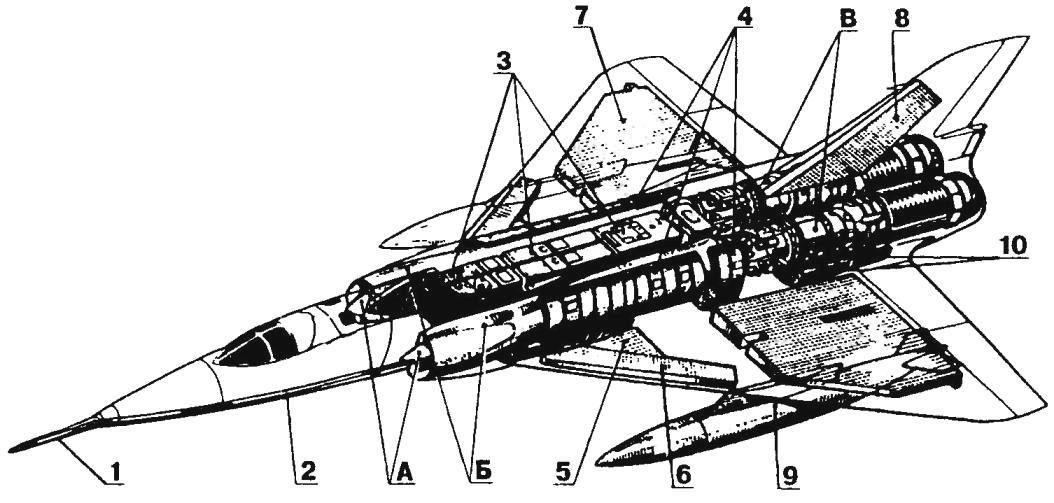
Fuel system and powerplant of the aircraft is MIRAGE IVA (A movable cone intakes; B— air channels; — turbojet SNECMA “Atar 9K” with afterburner):
1 — receiver of the in-flight fuel; 2 — the pipeline system refills; 3 — the Central fuselage tanks; 4 — side fuselage tanks; 5 — front tank-compartment of the wing; 6 — tank to wear wings; 7 — the Central wing tank; 8 — tank in the keel; 9 — suspended drop tank; 10 — rear fuselage tanks
In the process of upgrading MIRAGE IVA decided to equip the latest ASMP missile with a combined rocket-ramjet engine and a warhead capacity of 150 Kt. On the bomber instead of the nuclear bomb has installed a special suspension pylon and modified avionics, adding to the composition an inertial navigation system and radar Arcana with the mode of terrain mapping. This radar was used for the periodic adjustment of the navigation system in order to increase the accuracy of determining location coordinates of the aircraft. The use for this purpose, conventional radio navigation systems is considered impractical due to their poor noise immunity.
Ground tests missiles ASMP started in 1980. In 1983 took place the first launch from the bomber MIRAGE IVA. In the air the Navigator of the plane entered the coordinates of the starting point in the inertial system of the rocket. After a reset, the ASMP has joined its solid booster, which is five seconds broke up the rocket to a speed corresponding to the number M = 2. When the powder charge accelerator burned, in the case entered the main ramjet engine, the speed of ASMP led to redoubled sound at medium altitudes.
The range of the missile was significantly dependent on the height of launch and flight profile. At high and medium altitudes ASMP could fly 250 km, if the rocket was moving to the target at low altitude, the range was 80 km System of Autonomous inertial guidance, and because of this, the accuracy of hitting the target is low, the probable circular deviation of about 150 m, but for a nuclear warhead, this value is quite acceptable. Missile launch weight was 860 kg, warhead weight of 300 kg. In a combat flight, in addition to missiles on the bomber were suspended container with a length of three meters and a diameter of 160 mm broadband station “Barem” with controlled radiation power, which is generated noise. The carrier rocket (18 aircraft) received the designation MIRAGE IVP.
In 1996 the decision was made on the removal of bomber weapons. The aircraft were gradually attributed to the development of the resource.
DESIGN DESCRIPTION
The MIRAGE IVA aircraft is a monoplane with a triangular wing and retractable landing gear tricycle scheme. On production aircraft has two turbojet SNECMA “Atar 9К50” with the thrust of 6800 kg with afterburner.
The crew consists of pilot and Navigator-Bombardier, places which are located in tandem. Atomic bomb AN-11 or AN-22 located in an armored fairing under the fuselage. The aircraft is capable of speeds twice the speed of sound, and carries no defensive weapons, with the exception of equipment for the creation of radar jammers the air defense system of the enemy and shooting infrared traps.
The wing of the aircraft, which is based on the fender Mirage II, has a triangular shape in plan with a sweep angle of 60° to the front edge. The relative thickness varies along the span from 3.8 to 3.2 percent. This is the thinnest wing ever produced in France for military aircraft. It has no curvature on the toe and twist. The toe cap is made of washed down to improve the flow at high angles of attack. Anti-icing system on the wing there. The heating system is intended only for the engines and the windshield of the cockpit glazing.
The design of the wing are three main spar. The volume bounded by the side members, forms a trapezoidal tank compartment. The toe of the wing at the root is also used as a fuel tank. In the triangle between the front and Central rails, if you count the front located fuel tank compartment air brakes and a compartment main landing gear strut. Spars are used for machined parts and for sheathing mechanically milled panels. Ribs and the auxiliary elements are subjected to chemical etching to minimize mass.
For sealing of cavities of the wing joints of the parts sealed with sealant. Across the rear wing is located elevons, two on each wing, which are used for longitudinal and lateral control. Elevons and rudder are electro-hydraulic actuators. From the cabin crew manual wiring goes to the servos of the control surfaces, the deflecting surfaces at right angles.
The contours of the fuselage are only two side air intakes. A feature of the fuselage is the lack of weapons bays. The bomb is half recessed into the lower surface of the fuselage, and after dropping the remains in the fuselage recess. The space occupied by the bomb, closed the concave hull. After we dropped the bomb there is a slight imbalance, which kompensiruet pumping fuel into appropriate tanks. On the outer walls of the inlet channels has a special rubber coating. To isolate the rear fuselage from the afterburners used tube of titanium, separating the camera from the fuselage, a casing of heat-resistant fiberglass, and finally, a special rubber coating.
The keel of the aft fuselage consists of a front spar ribs rear spar trailing the caisson. The keel fit through the seven overlap with the respective seven frames of the fuselage. Plate, locking flange, together with two milled panels forms a tank compartment with a capacity of 500 liters In the keel applied the same containment system as the wing. The rudder is equipped with a yaw damper.
The fuel system consists of left and right side feeding the respective motors. There is a connection between the tanks of the left and right parts, and possibly cross-powered engines. Fuel pumps are duplicated, and one pump can ensure the flight of the aircraft at subsonic or supersonic cruising mode. Consumables are the left and right front tanks of the fuselage, they are in a predetermined order is supplied fuel from the other tanks. The aircraft can refuel with fuel in flight.
The chassis consists of two main columns with the trucks and the a-pillar with dual wheels. The pressure in the pneumatic main landing is about 12 ATM, so you can use the landing paths of NATO. The pressure in the tires of the nose landing gear 8 ATM. The cylinder of rotation of the strut acts as a damper “shimmy” and simultaneously ensures centering. Front removed back on the flight.
Performance characteristics strategic bomber MIRAGE IVP
Wingspan, mm……………………….11 850
The length of the plane, mm……………………23 500
Aircraft height, mm…………………….5400
Wing area, m2…………………………..78
Weight of empty aircraft, kg……….. 14 500
Takeoff weight, kg……………………..31 600
Maximum
takeoff weight, kg……………………33 475
Unit load on wing, kg/m2 …. 405
Maximum speed, km/h……….2340
Landing speed, km/h……………..260
The length of the run
with full load, m………………..1700
Time climb 11 000 m
without external suspensions, min………..4,25
Ceiling, m………………………………… 18 500
N. Food reserve was, A. CHECHIN, Kharkov
Recommend to read
 THE CONTAINER UNDER THE FLOWER
Modern plastic pot from under the Packed products have nice shape, and often color. The deepest of these, may then serve as containers for growing seedlings or suspended pots for indoor... FOR THE DISCO? FOR THE ENGINE!
Strobe and underlying his actions the same-name effect find application not only in discos, no matter how popular, attractive ones. And technology is no exception. How to make strobe...
