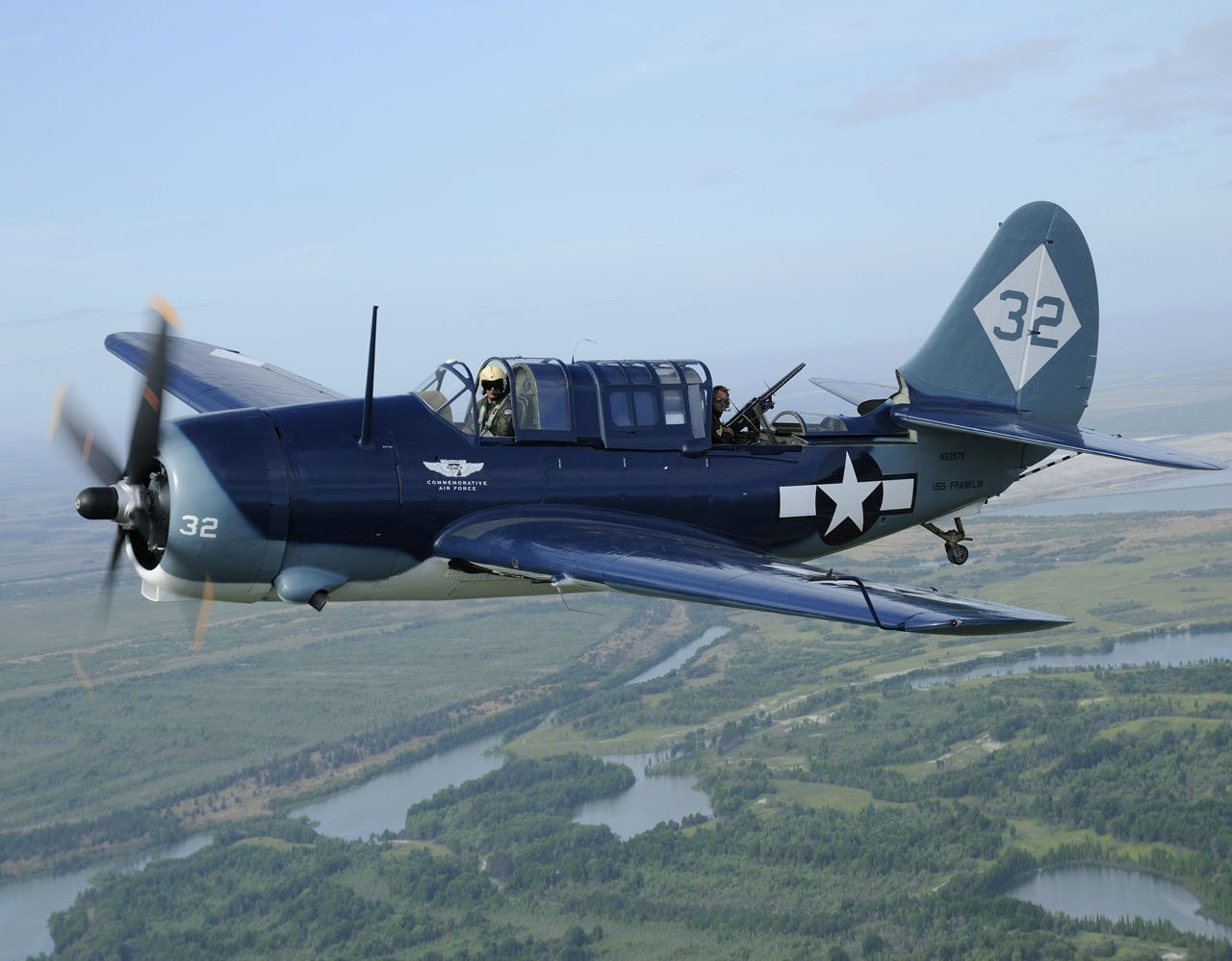
 Carrier-based scout CURTISS SB2C HELLDIVER. In early 1938, the Bureau of Aeronautics of the U.S. Navy has developed the conditions of tender for the construction of a new deck of ramedica-bomber engine Right XR-2600 Cyclone. The dimensions of this plane involved the simultaneous placement of two such devices on the platform size 14,6×12,2 m samoletostroenie carrier. This requirement was most difficult to meet. Binding was considered as mechanisms for folding wings on the deck and the landing gear in flight.
Even before the official announcement of the competition, several firms have already started to develop aircraft for this project.
The time allocated to the competition — until December 1938, completed only four of the six participating firms. Four projects were selected only two companies Curtiss and Bruster, who was designated as the XSB2C (firm Curtiss) and XSB2A (company Bruster).
Both projects involved the use of a new engine that met the minimum conditions of competition, and the car had a lot in common: all-metal construction, folding up the wings, a large bomb Bay, retractable landing gear in flight and flaps. The Navy chose the Curtiss aircraft company, the geometric dimensions of which allow the main condition of the competition is to place two aircraft on the lift.
XSB2C outwardly resembled the previous design of the company, in particular biplane SBC Helldiver, and, in fact, the new machine was its deep modernization. This is what determined the range of complex issues that are decided by the designers. For the transition to the monoplane scheme had to pay for the increase in wing loading and peretyagina design, to the same old layout, the tail section did not allow to place there guns to protect the rear hemisphere. On the solution of these problems, the engineers under the leadership of Raymond C. Blaylock worked throughout the design phase.
The contract to build the advanced aircraft fleet was made with the Curtiss firm in may 1939. The contract involved the static test and demonstration flights of the prototypes. At the end of may, the special Committee approved the layout of the prototype. However, the purchaser has required the design of additional changes relating to wing-mounted weapons and the aft machine gun.
During the tests, full-scale mockup in the wind tunnel it was found that the maximum lifting force is much less than estimated. With the aim of achieving the estimated parameters had to increase the wing area from 35,767 to 39,205 m2 and change its structure. Then it turned out that the dive speed is slightly higher than the estimated. The problem is solved by the installation of the trailing edge of the wing brake flaps, which were used on landing.
Test pilot Lloyd Childs 18 December 1940 and made its first flight on an experimental machine ХЅВ2С2С-1 (serial number 1758) from the airport in Buffalo, new York. Tests in air revealed numerous construction defects. The plane was very difficult to pilot. A curious case occurred on 9 February 1941, during takeoff from the prototype plane took off… the engine. After amplification of the attachment of the engine testing continued. Another surprise, the plane was presented may 10: when landing, he came off the left wheel. The reason was found very quickly — fatigue material.
During testing, there were a lot of changes to the engine cooling system. In August 1941, to improve the static stability of the engine on the aircraft was moved to 305 mm forward. Prototype ХЅВ2С2С-1 flew on November 12 at the airport in Port Columbus to military trials, where on December 21 when performing a dive from a height of 6706 meters due to exceeding max of the plane ripped right console wing and stabilizer. The prototype has completely collapsed and was beyond repair. The pilot miraculously managed to leave the car unattended and be saved. This incident has delayed flight testing for another six months.
Oddly enough, accidents and failures almost no effect on the fate of the order. The fleet was looking forward to supply 370 aircraft under the first contract, signed in 1940 under the new defense program. Assembly line for the XSB2C-1 was ready in December 1941. Paced Assembly production aircraft — 85 cars a month.
The Japanese attack on pearl Harbor on December 7, 1941, have given more importance to the programme of issue XSB2C highlighting its priority. The first production SB2C-1 (No. 00001) collected in June. This machine had significant differences from the prototype. Designers redesigned the wing, replaced the sight in the cabin arrow mounted two 7.62 mm machine guns (instead of one 12.7-mm), mounted search radar ASB. To increase the survivability of the cockpit is covered with armor and fuel tanks made Proektirovanie.
The first flight of the serial HELLDIVER (“Hell dive bomber”) made on 30 June 1942. In August, rolled off the second serial instance (No. 00002). In early September, they both flew to the air base in Anacostia, where he continued testing of the power plant. In October, the aircraft No. 00002 flew to the air base NAF in Philadelphia, where he began test flights from the deck of an aircraft carrier. At the same time at the air base in Norfolk in the plane No. 00004 were tested missile and bomb armament. On the third serial of the Curtiss SB2C HELLDIVER had a hydraulic system of the brake flaps. Later it was used on 201 series aircraft along with new 20-mm cannon mounted in each wing instead of two 12.7 mm machine guns. Instance No. 00006 were tested in the interests of the air force at Wright field. At No. 00007 air force base in Anacostia tested radio and electrical equipment. In the instance of No. 00008 passed speed tests at Norfolk, and No. 00013 determined the possibility of arming torpedoes. Carrier-based reconnaissance and bombers.


Carrier-based scout bomber Curtiss SB2C HELLDIVER:
1 — four-bladed variable-pitch propeller; 2 — engine; 3 — tunnel air intake of the carburetor of the engine; 4 — the elements of the motor of the engine; 5 — tank hydraulic system; 6 — dashboard; 7 — bulletproof glass; 8 — scope, 9 — the pilot seat; 10 — headrest; 11 — fuel filler fuselage fuel tank; 12 — fuselage fuel tank; 13 — liferaft; 14 radio; 15 — machine-gun turret; 16 — 7.62 mm machine guns; 17 — unit radio; 18 — power set of the keel; 19 — rib of the rudder; 20 — brake hook; 21 — absorber tail landing gear; 22 — cables control system; 23 — cylinder cleaning them; 24 — frames of the fuselage; 25 — cartridge box; 26 — the attachment points of the machine gun turrets; a 27 — seat radioman; 28 — 454-kg bomb; 29 — rod take-out bomb over the rotor swept plane; 30 — armoured fire power divider; 31 —the oil tank; 32 — oil cooler; 33 — accumulator; 34 — the exhaust pipe; 35 — the exhaust manifold of the engine; 36 — position main landing gear; 37 — unit rotation stand; 38 — oblique strut; 39 — the main strut; 40 — flaps stand; 41 —pneumatic wheel of the main stand; 42 — wheel axle; 43 — fork stand; 44 — brace stand; 45 — Kok sleeve screw; 46 — a three-blade variable-pitch propeller; 47 — tripping; 48 — LDPE; 49 — sliding part of the cockpit canopy; 50–hatch filler fuselage fuel tank; 51 — the access hatch to the life raft; 52 — sliding part of the canopy radio operator-gunner; 53 — the tail wheel; 54 — fairing tail landing gear; 55,79 — sash bombolyuka; 56 — fold bleed air cooling oil cooler; 57, the air intake channel cooling oil cooler; 58 — mounting clamp sight; 59 — upper panel of the dashboard; 60 — lower panel of the dashboard: 61 — rudder; 62 — the radio antenna; 63 — fairing (lowered); 64 — the canopy radioman (in open position); 65 — the canopy pilot (in open position); 66 — visor canopy; 67 — hour radio station, 68 — adjustable cooling jacket of the engine; 69 — external fuel tank (PTB) with a capacity of 200 l; 70 — the hinge of the rudder: 71 — trimming the rudder; 72 — cylinders control the doors of the bomb Bay; 73 — auto slat; 74 — fold console wing; 75 — outside the fairing (in raised position); 76 — end rib of the center section; 77 — fairing exhaust pipe; 78 — section perforated brake flaps (on late series aircraft); 80 — wing-mounted 12.7-mm machine guns; 81 maintenance access doors control system; 82 — radar antenna; 83 — ANO; 84 — Aileron; 85 — hinge Aileron; 86 trimmer Aileron; 87 — section brake flap (first series); 88 — hiltonbritney; 89 — blade stabilizer; 90 — handlebar height; 91 —trimmer of the Elevator; 92 — guide rollers of the slat; 93 — 20-mm gun; 94 maintenance access doors access the cartridge boxes; 95 — the hinge of the Elevator; 96 nodes turning left wing; 97 — the line joining the center section and left wing; 98 maintenance hatches guns; 99 — the handle of the Elevator control and ailerons; 100 — trigger control wing-mounted missile launchers; 101 — PTB capacity 280 l; 102 — PTB capacity of 200 l (late version); 103 — section brake flap in a landing position; 104 — rockets
The most significant difference was the replacement of the four wing-mounted 12.7-mm machine guns two 20-mm cannon. There is a new opening mechanism of the flashlight radio operator-gunner and backup hydraulic control system for air brakes. Curtiss SB2C-1C HELLDIVER released in the amount of 778 copies. During 1944 “Helldiver” new modification replaced the early series aircraft. SD2C-1C became … aircraft radar set AN/APS-4. Receiving and transmitting antennas fixed on the lower surfaces of the folding wing panels. This modification received the designation SB2C-3E, and release it amounted to about 10 percent of all commercially released SB2C-3. The firm Curtiss built the 1112 instances of the SB2C-3, 413 – SBW-3 and 150 – SBF-3 (in Canada).
… bone fuselage fuel tank, the lack of spinner is changed by the cockpit canopy and new exhaust system brake hook. On the plane finally abandoned the outdated radar ASB, if necessary, installed standard radar AN/APS-4. The release of new modifications began in February 1945 and a few new Curtiss SB2C-5 HELLDIVER before the end of the war managed to arrive in the combat units. In all there were 970 serial SB2C-5 of them before the end of the war, 470. 85 more aircraft under the designation SBW-5 was built in Canada.
Curtiss SB2C-5 HELLDIVER remained in service with units of the Navy and after the war, however, in combat units he did not stay long. In 1949, the aircraft was transferred to the training squadron. In the first half of 50-ies “hellday-faith” was taken out of Naval aviation.
In the framework of military aid to the SB2C-5 was exported to France, Italy, Greece, Portugal and Thailand. In these countries, “Helldiver” remained in combat units much longer. So, in the Greek Navy SB2C-5 was replaced by jet F-84 only in 1953.
French and Thai Curtiss SB2C-5 HELLDIVER participated in anti-guerrilla combat operations in Southeast Asia. In Italy, the SB2C-5 was used as a patrol aircraft until mid-1957.
Modification XSB2C-6
Two prototypes of the last modification of the Curtiss XSB2C-6 HELLDIVER built in 1944. This converted aircraft SB2C-1C, which were installed new engines Right R-2600-28 capacity 2100 HP due To their increased size had to redo the hood. The new machine had a much better performance than the SB2C-5, but is not interested in fleet command. Both aircraft were later used to test various aircraft systems.
The project XSB3C-1
This is a completely new aircraft that was to replace the “Helldiver”. It was supposed to set the engine Right R-3350-8 power 2300 HP and a new chassis. However, the work was curtailed because of lack of interest they command. Due to the lack of order, the car remained in the stage of model design.
THE DESIGN OF THE AIRCRAFT
Curtiss SB2C HELLDIVER — double-metal single-engine scout-bomber, made according to the monoplane scheme. The plane was designed as a carrier-based with option based on all existing aircraft carriers of the United States.
The all — metal fuselage is semi-monocoque. The fuselage — duralumin sheets. In front of established steel fire partition, performing the functions of the power frame to which is attached to a motor mount of the engine. Behind the partition housed the cockpit, separated from the rest of the fuselage armored plates, which was the main fuselage fuel tank tested. Under the cabin housed a bomb Bay for a fuel tank — power station and rescue equipment used during a forced landing on the water or out of the airfield.
Then came the cabin, the radio operator, in which the turret has been fixed spark machine guns. To increase the field of fire outside the fairing was.
In front of the bomb Bay was the ramp for the ejection of the bombs outside the rotation of the propeller blades. This mechanism is used when the bombing a steep dive. On the ramp were fixed, one 454-kg bomb. In another embodiment of the combat use of the bomb Bay could accommodate two 227-kg bombs.
Equipment cockpit includes a full set of flight and navigation instruments on the Central panel of the dashboard. On the side panels is attached to the power station, the bomb armament panel and control lever engine. On the right side of the cab mounted brake lever flaps used for the takeoff, landing and during dive bombing.
Control plane standard, handles and pedals. Since the modification SB2C-1C aircraft equipped with a hydraulic release system brake flaps. The cockpit of the closed type, with slide-back canopy. The front armored glass. Gunner, in addition to working with radio and protection of the rear hemisphere, serviced radar equipment — original ASB, and then under the index of the AN/APS-4.
Cantilever two-spar all-metal wing is structurally consisted of three parts, a center section and folding up consoles. The wing — dural. V-wing cross 6°, the installation angle of attack of 1.5°. On the front edge of the consoles were located automatic leading edge slats on the trailing edge of the wing and the inner part of the console (top and bottom) — the brake pads. Starting with the later series SB2C-3 steel perforated flaps. Ailerons of large area on the wing tips had dural power set and a fabric covering. Aileron — trim.

Empennage cantilever, classical type, mixed design. Stabilizer without transverse V, the adjusting angle is +3°. Keel declined by 1.5° to the left to compensate for torque from the propeller plane. The covering of the keel and stabilizer dural, and the rudder and height and fabric. On the rudder, and altitude were the trimmers.
Chassis tricycle, tailwheel. The main stands were placed in special niches in the center section of the wing, the tail, covered with a fairing, had not been cleaned. Amortization of landing gear — oil. System retract — hydraulic. The main landing wheels were equipped with drum air brakes. The tires of the main wheels had the dimensions 812×223 mm. tail wheel — 203×114 mm.
The power plant of the aircraft consisted of 14-cylinder air-cooled engine Right R-2600 Cyclone power 1900 HP Engine was completed with a three-blade (the first series) or four-bladed propeller.
The armament of the aircraft consisted of five 12.7 mm machine guns: four wing and one on the turret in the cockpit, radio operator-gunner. In the later series had wing two 20 mm cannon and the turret at hand — two 7.62-mm machine gun. In the bomb Bay housed one 454-kg or two 227-kg bomb, and wing bomb racks for two bombs of 227 kg. since the modification SB2C-4 aircraft could carry up to eight unguided rockets HVAR caliber 127 mm.
Flight characteristics of the aircraft SB2C-4
Wingspan, mm………………………..15 540
Length, mm………………………………….. 11 176
Height, mm…………………………………….5165
Wing area, m2…………………………39,2
Empty weight, kg…………………………….4704
Normal takeoff weight, kg……….6436
Maximum takeoff
weight, kg…………………………………………7700
Maximum speed, km/h…………..474
Practical ceiling, m………………….8870
The rate of climb, m/s……………………9,15
The maximum flight range, km 1990..
N. Food reserve was, A. CHECHIN, Kharkov


