Many letters received by the editors indicate the great interest of readers in the “Small Mechanization” competition held by the magazine. And this is no coincidence. Since there is still not enough equipment produced by the industry, gardeners and owners of personal plots make walk-behind tractors on their own.
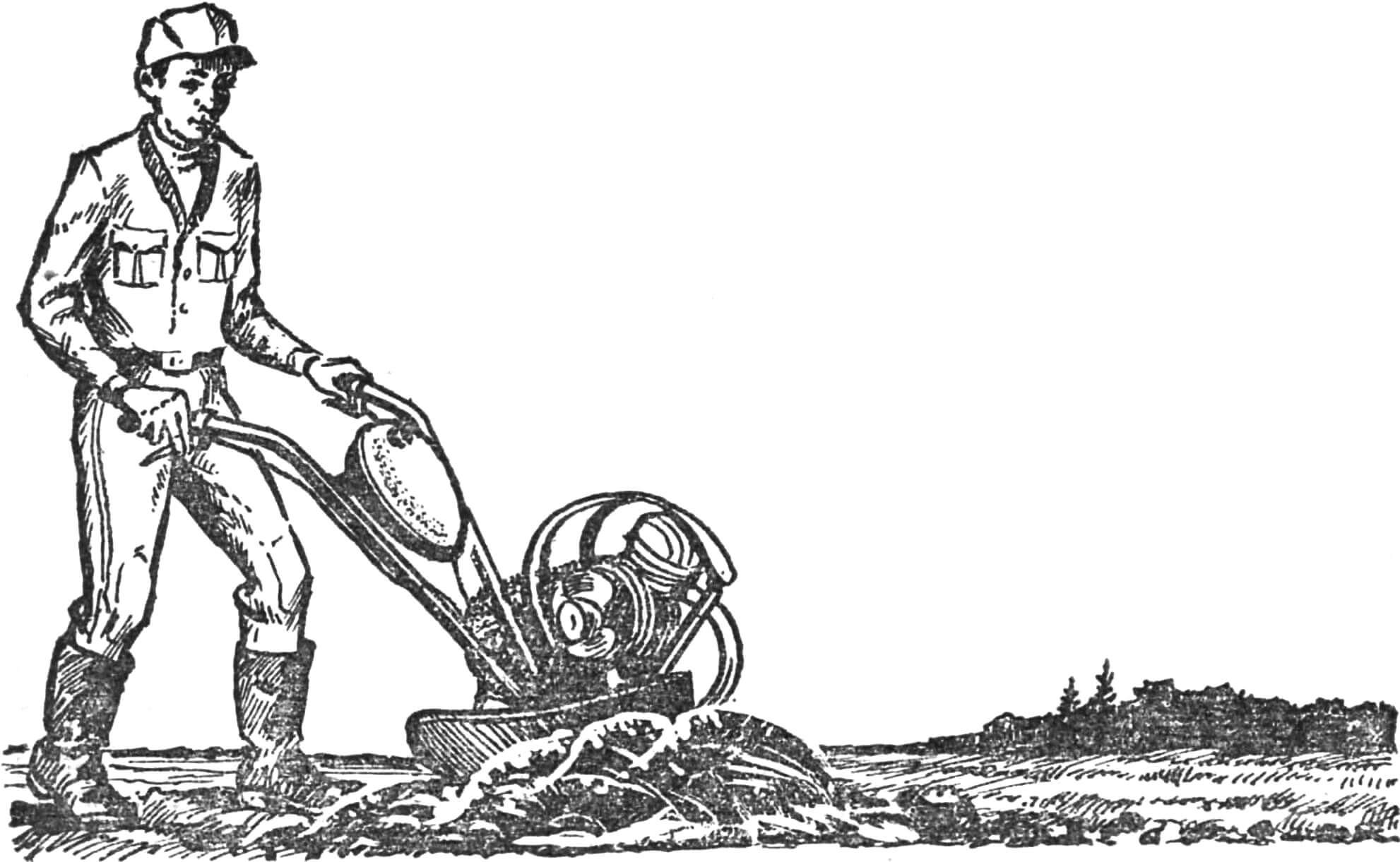
Sometimes you get surprisingly simple and convenient designs. For example, can an old horse-drawn plow be propelled by a small moped engine and still plow a vegetable garden? But it is the D-6 that is the power plant of N. Gagarin’s motorized plow from the village of Shchelkun, Sverdlovsk region. The whole secret is in the unconventional layout, thanks to which the motorized plow (this is really a plow with a motor) turned out to be light, compact and maneuverable.
However, let’s give the floor to the author.
One day I found an old horse-drawn plow in a landfill, produced before the revolution. I really liked it for its simplicity, thoughtfulness and, if you like, elegance. I brought it home, but since I don’t have a horse, the plow was lying in the yard until the idea came up to put it on wheels, or rather on a wheel, and equip it with a motor. In other words, I decided to build a small motorized plow, mentally coming up with a name – “Mole”.
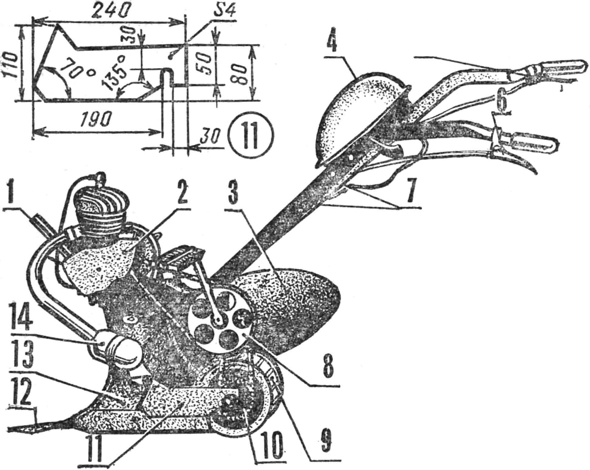
1 — engine frame, 2 — D-6 engine, 3 — plow share, 4 — fuel tank, 5 — gas lever, 6 — clutch lever, 7 — standard handles of a horse-drawn plow, 8 — sprocket Z = 48, 9 — wheel with lugs, 10 — sprocket Z = 28, 11 — left wheel bracket, 12 — trimming knife, 13 – plow body, 14 – muffler.
My “Mole” differs from traditional designs in its layout: the plow itself serves as the basis for installing all components and parts. At the top, in the front part, there is a D-6 engine, connected by a chain transmission through an intermediate shaft to the impeller, which is located in the lower part behind the ploughshare. Thanks to this arrangement, the design turned out to be quite light (weight only 40 kg). When the motor-plough moves in the furrow, the layer creeping onto the ploughshare serves as ballast, ensuring reliable adhesion of the impeller to the ground.
Most of the parts are industrially made, taken from mopeds and motorcycles, but some components had to be made independently. Naturally, the horse-drawn plow itself underwent modifications: it cut off the drawbar to which the lines clung, and reduced the grip width of the trimming knife by 100 mm. To lengthen the control handles, I used cut-off parts of a moped handlebar along with the clutch and brake levers. The throttle cable was connected to the latter.
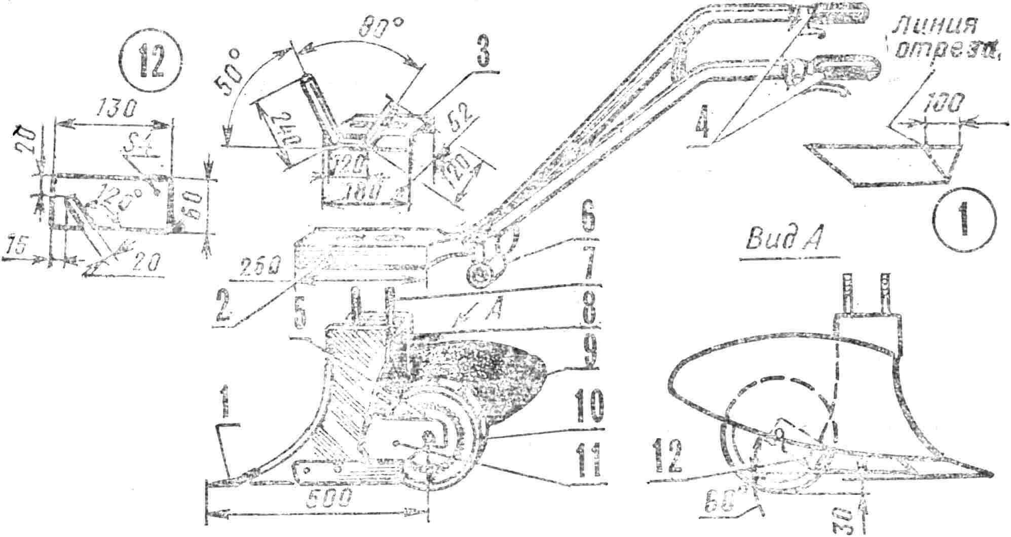
1 — trimming knife, 2 — supporting beam, 3 — sub-frame with flange, 4 — control handles, 5 — sprocket Z = 28, 6 — intermediate shaft bushing, 7 — M14 bolt, 8 — plow body, 9 — ploughshare, 10 — wheel with lugs, 11 — left wheel bracket, 12 — right wheel bracket.
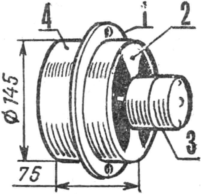
The impeller is installed in the dam space on brackets welded to the plow body. The right and left ones differ in shape and are cut from sheet steel with a thickness of 5 and 8 mm, respectively. As an impeller I used a hub from the Izh-Jupiter K motorcycle. To increase its area, on the right side of the rim I welded a ring curved from a 15X10X1.5 mm corner, and on the left to the hub – a drive sprocket Z = 28 for the SZA chain. To increase traction with the ground, nine lugs from 20X20X2 mm corners are welded to the rim.
The sub-engine frame is curved from a steel pipe Ø 27 mm. A flange with oval holes for M14 bolts is welded to its horizontal part; they connect the plow body with the supporting beam and the frame flange. The openings of the supporting beam also have an oblong shape. This was done to adjust the tension of the chains.
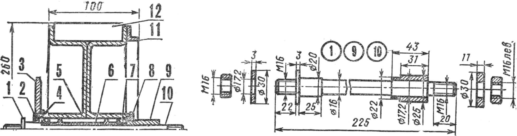
1 – washer, 2 – felt seal, 3 – sprocket Z = 28, 4 – retaining ring, 5 – hub, 6 – internal spacer, 7 – bearing No. 203, 8 – hub nut, 9 – bushing, 10 – axle (from axle of the front wheel of the motorcycle “Izh-Jupiter K”), 11 – depth limiter (ring from an angle 15X10X1.5 mm), 12 – lug (angle 20X20X2 mm).
On the left side of the heel of the supporting beam, the intermediate shaft housing with a bracket is welded. The body is made of pipe with an internal Ø 40 mm. The axle of the connecting rods of a road bike is mounted in it on M203 bearings. The bearings are pressed in with significant force and do not require additional fixation. On the left side of the intermediate shaft there is a standard bicycle sprocket Z = 48 with a connecting rod and a pedal – for convenience when starting the engine. A cut connecting rod with a Z = 13 sprocket welded to it is installed on the right. The intermediate shaft bracket is made of a rectangular pipe 60X30 mm with a wall thickness of 3 mm.
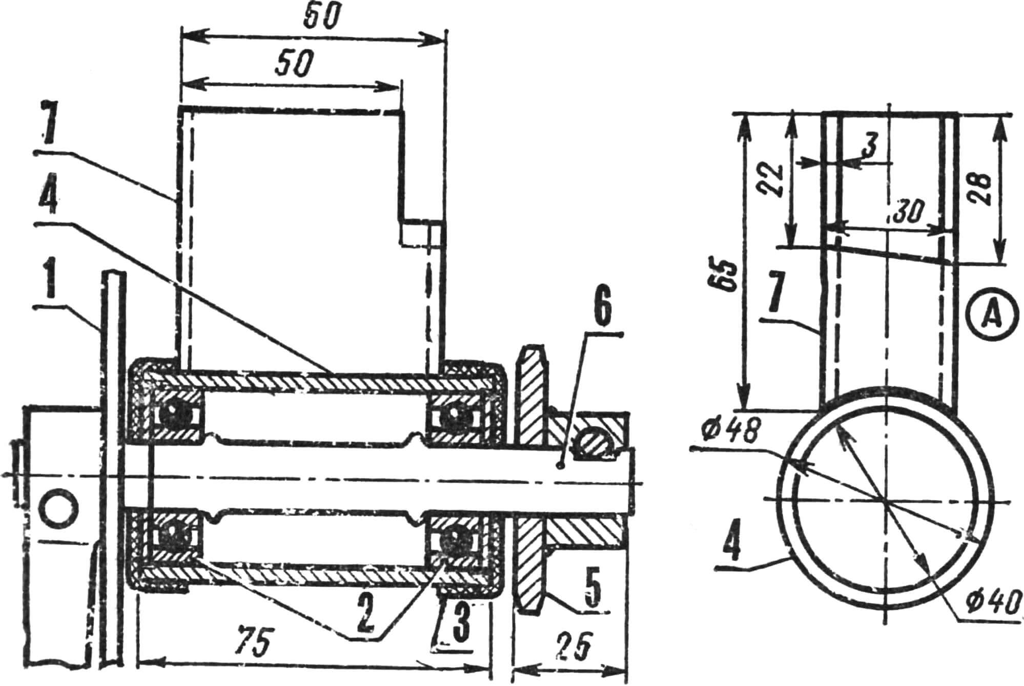
1 — bicycle sprocket Z = 48 with connecting rod and pedal, 2 — bearing No. 203, 3 — cap, 4 — intermediate shaft housing, 5 — sprocket Z = 13, 6 — intermediate shaft, 7 — bracket. A – side view of the intermediate shaft housing with bracket.
The fuel tank is taken from a moped and installed on a piece of pipe welded to the control handle coupler. Fuel flows by gravity.
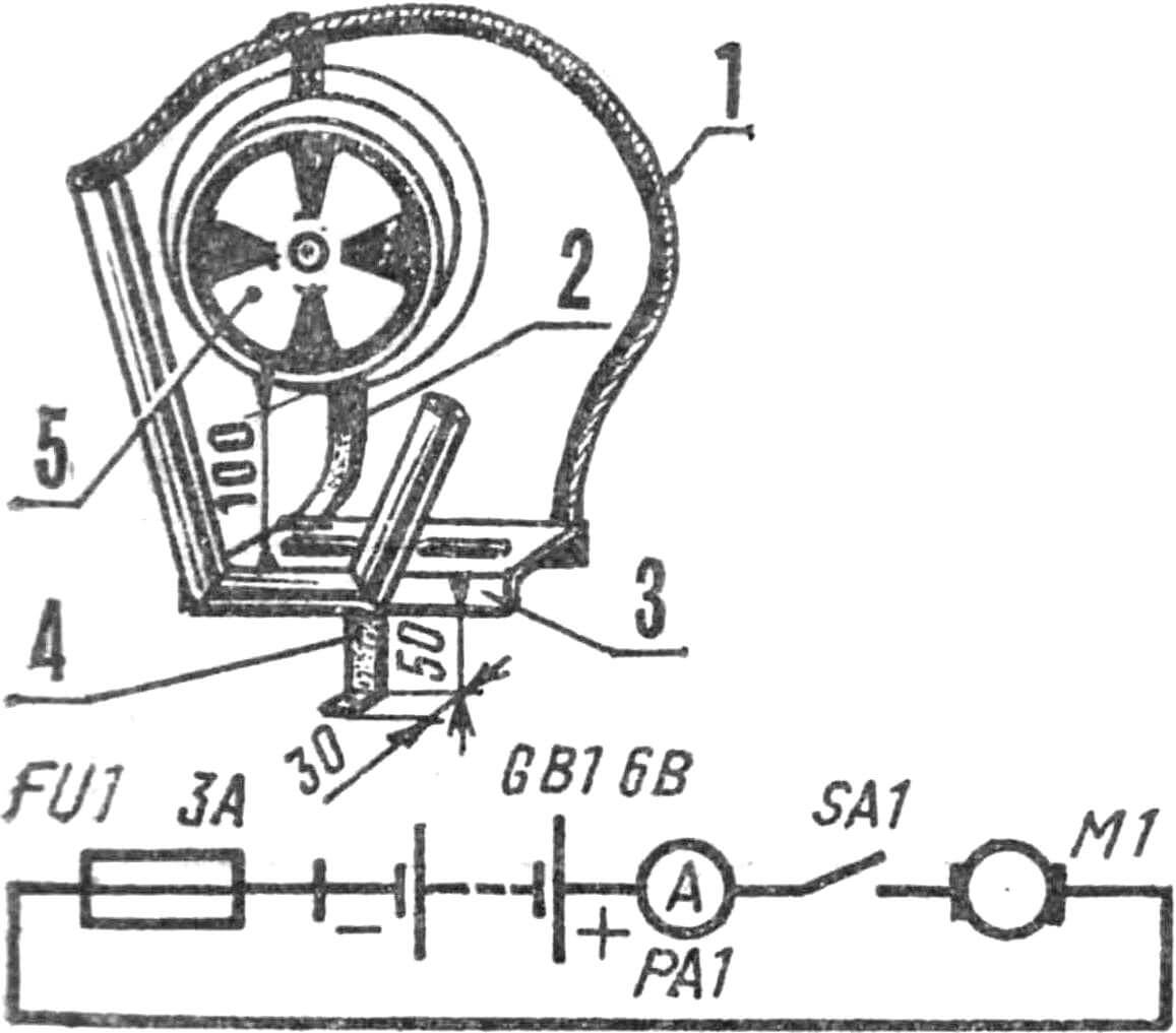
1, 2 — fan casing brackets, 3 — sub-frame flange, 4 — muffler bracket, 5 — fan in the casing.
Electrical diagram of the cooling system.
To cool the engine, an autonomous cooling system has been developed, but not yet tested, consisting of a 6 V 15 W electric motor with a four-blade impeller, a ZMT-8 motorcycle battery, an ammeter, a 3 A fuse and a switch. The electric motor consumes a current of 2.5 A. The battery capacity is enough for 2.5-3 hours of continuous operation, after which the battery must be recharged. The motor with the impeller is fixed with M6 bolts to the eyes of the casing taken from an old vacuum cleaner. To install the cooling system, it is necessary to weld an arc and brackets from a steel plate with a cross section of 30X4 mm to the motor frame with a flange; The fan casing is attached to them using M6 bolts. The battery is located on the right supporting beam and secured with clamps.
1 — casing mounting flange, 2 — casing eyes, 3 — electric motor, 4 — casing.
In operation, the motor plow showed good maneuverability, stability in the furrow, and most importantly, it turned out to be convenient to use. To start the engine, you need to lift the plow by the control handles so that the impeller comes off the ground, and unscrew the intermediate shaft pedal. One more note: the tension of the chains is carried out by moving the power units relative to each other, followed by reliable fixation with M14 bolts. Thanks to this system, the tension is adjusted once a season, before the first plowing of the site.
BASIC TECHNICAL DATA OF MOTOR PLOW “MOLE”
Length, mm 1300
Width, mm 700
Height, mm 850
Working width, mm 180
Engine D-6
Speed, km/h 4
Weight, kg 40
N. Gagarin, p. Schelkun Sverdlovsk region
Recommend to read
 UNIQUE ROCKING
One of the most important components of the control system with cord model airplane rocking chair that serves as the connecting link between the cord strands and rods for the rudders.... SCISSORS WITH RULER
They say: "measure twice — cut once", but if one of the shear blades to cause a spark or graviroval marker centimeter scale, as shown in the figure, from a preliminary marking in many...
