The proposed technical solutions give the bike additional consumer properties: increase torque for the same effort, the cyclist and drivetrain efficiency.
TELESCOPIC ROD
As you know, to change torque in a Bicycle transmission in two ways: either throwing the chain on sprockets of different diameters (both leading and trailing), or changing the radius of rotation of the pedals (cranks). At the time of publication on such designs was in the journal “modelist-Konstruktor” (for example, number 3 in’02).
Each design, along with the advantages, there are drawbacks: one is detected by the inconvenience of switching speeds, the other with the comparative complexity of the mechanism of change of torque. In the proposed pedal the drive working on the second principle (the change in length of the connecting rod), the first drawback is missing completely and the other is minimized since its design is simple.
The new drive is additionally mounted other rods — telescopic. Staff left because they do not interfere with the operation of the actuator (axis pedals have been removed) and, in addition, serve as additional supports for telescopic rods. They consist of a body — tube 25x25x2 mm, inside which he walks freely extendable rod — a steel rod is also square section 20×20 mm.
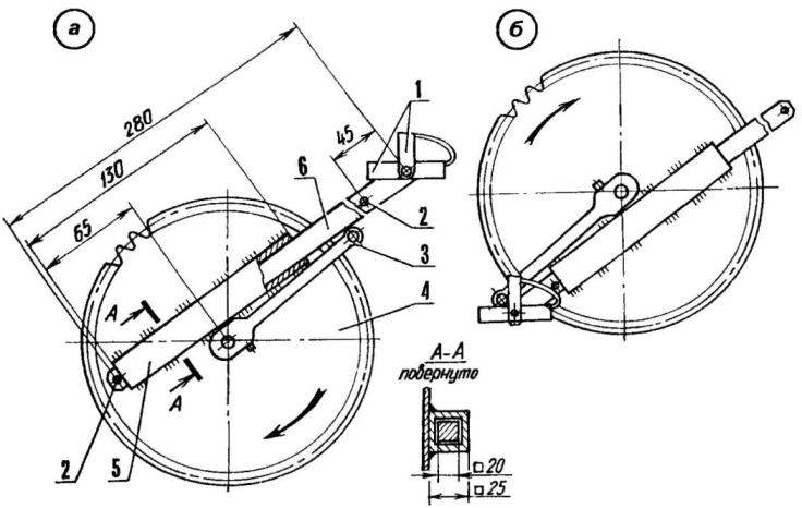
The bike with the telescoping rods extended maximum (a) minimum and (b):
1 — pedal tulipson; 2 — pins (rod d8); 3 — staff rod; 4 — sprocket; 5 — the telescopic housing of a rod (pipe 25x25x2); 6— extendable part of the telescopic rod (rod 20×20)
The casing is mounted on the sprocket close to the standard rod and welded short beads to the star. Can be welded to the rod, but then the design will be less reliable. Therefore, the left on a carriage shaft it is better to install the connecting rod with an asterisk. At one end of the rod pull-out rod is drilled a hole with a diameter of 12.7 mm, threaded М14х1,25 (under the pedal) and is attached to the pedal tulipson, taken with the standard drive.
Move the retractable rod in its housing is limited by two projecting pins, pressed into his body from different sides of the pipe corps.
Additional features of this drive compared to regular, discloses the following technology drive. When the pedal is at the top, the cyclist slightly lifts the leg and using toeclips pedal selects a desired road conditions on the length of the retractable rod, and then presses on the pedal. When approaching the pedal to the bottom point rider straight leg, ceasing to push on the pedal, inserts the rod into the housing until it stops. The same steps, but in opposite phase, the cyclist executes simultaneously with the other leg on the opposite connecting rod. The axes of the pedals travel in an oval path. About advantages of the elliptical sprocket before the usual round in Bicycle transmissions has been said in print, including in the journal “modelist-Konstruktor”.
Thus, the proposed telescopic rods give drive bike the advantages of the transmission with an elliptical drive sprocket without its drawbacks. To the entire, drive and simple to manufacture.
DRIVE WITHOUT “DEAD” ZONES
Of the many devices that increase the power and efficiency of weltrangliste, elliptical sprocket is the most successful and simple. It is attached to the rod so that the sector of maximum pressure on the pedal (which is an angle slightly greater than 90° for each pedal) torque provides the semimajor axis, and the other zones scroll faster thanks to the minor radius of the elliptical sprocket.
Somehow in the discussion of the advantages and disadvantages of various rectangular and sliding the leading sprockets, connecting rods of different lengths and shapes have suddenly itself the idea of almost instant scrolling “dead” zones that make up an angle over 180° for each pedal and round the leading asterisk. The implementation of the idea is allowed to work the legs alternately and only in the area and the maximum load, and thus significantly improve the efficiency of a pedal of a drive. To develop a simple and effective device was a matter of technique.
So, the sprocket is disconnected from the connecting rod and freely installed welded thereto a hub on the carriage shaft between the connecting rod (ground off with emery on the bench under the asterisk) and the frame. To dislodge the rod from the sprocket holes can be fairly easy, if you put an asterisk in the jaws of a large vise so that the rod was between them, and then inserting a connecting rod in an old carriage or cut commensurate with the pipes once or twice to hit it top heavy with a hammer.
Veloplivd without “dead” zones (in the main view of the housing of the carriage not shown):
1 — drive sprocket; 2 — escarpment (45 steel, 4 pieces); 3 — BB shaft; 4 — hub (steel 45); 5 — bilateral tooth (45 steel); 6— tulips; 7 — a pedal”sole”; 8— bushing (housing two bearings 200); 9—pedal shaft; 10 — the bearing 200(2 PCs); 11 — rod; 12—the case of the carriage
To the sprocket through 90° welded four of the support ledge. The design of the pedal is changed; now rotates the housing of the pedal on the axle and the axle itself and is rigidly welded thereto a pedal”sole” tulipson. On a regular axis pedals protectives axle on which is mounted a pair of roller bearings 200 series pressed into a steel bushing, and the bushing is welded to the connecting rod. The end of the axis protecive up to a diameter of 11 mm, is discharged to the outside and it is at an angle of 450 to the base is cut a face groove, in which is welded a bilateral tooth, periodically come in contact with ledges of the big stars.
During the rotation of the connecting rod, the position of the plane of the pedal”sole”, and therefore, the tooth remains almost unchanged, which periodically allows the tooth to enter into engagement with the ledges (in working area), ensuring the transmission of torque to get out of it (in dead zone). At this time, the ineffective parts of the trajectory traversed by the pedals almost instantly, and the effectiveness of veloplivd as a whole increases. As you can see, “sole” with tulipani need for the right leg and serves to keep the pedals from turning due to its reaction with the thrust of the ledges.
The left connecting rod with the usual pedal effect upon its working stroke through the carriage shaft to the right the connecting rod and through his tooth on a ledge of the drive sprocket. In this case the right foot pulls the pedal”sole” for toeclips up and stop while holding the “sole” in a horizontal position. Braking is carried out similarly to the reverse rotation of the connecting rod.
V. GAVRILOV, village of Inozemtsev, Stavropol Krai
Recommend to read THE FISH ARE BITING! Fun — fishing in open water. With the early spring as soon as the ice recedes, and until late fall the true fisherman whenever possible, in a hurry to the pond with the hope of a... DRILL ON THE TABLE There was a time when to the store to buy any device, especially metal cutting machine tools was difficult. And was expensive, and a run of outlets had. Today to buy such a product just...

 Not the first time the editors publish original contributions on the improvement of the Bicycle, the author of which is an inventor, engineer Vladimir Gavrilov from the village of Inozemtsevo area of Zheleznovodsk in Stavropol region. With his enthusiasm, he engages in technical creativity and other. An example of this— the second development in this publication, by V. Gavrilov together with his fellow villager M. Losev.