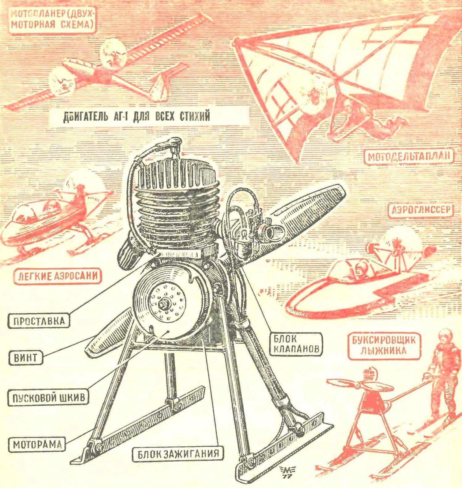
OR “15 HORSES”, WHICH WEIGH 12 POUNDS. In the range of domestic internal combustion engines which can be guided to create all-terrain vehicles Amateur designers, there are still no models working volume of 125 cm3, with sufficient specific capacity and acceptable specific weight (about 0.8—0.9 kg per horsepower). Attempts to adapt motorcycle engines — the M1A and the like — associated with a time consuming job to remove the gearbox and rework the ignition system to more easy and reliable. But if you have a good engine class 125 cm3 would increase immeasurably the possibility of creating light planes, ekranolyot and gliders.
This engine built in Amateur conditions. Engineer A. Gerashchenko has solved this problem very cleverly, using a number of parts discontinued outboard motors that can be discharged through the Mail (these details are on sale now at discount prices).
Engine test A. Gerashchenko has shown that it is very similar data to the currently best foreign samples.
On most serial printers easy transport crank chamber in the crankcase with rare exception, along with the pistons are used as scavenge pumps. Therefore, the technical parameters of such engines — liter capacity and efficiency are directly dependent on the degree of filling of the combustible mixture in the cylinder (above the piston). And filling cylinders with a mixture primarily depends on the quality of work of the intake system, the main purpose of which is to provide the most complete filling of the crank chamber, i.e. the volume below the piston, fresh gas mixture.
In two-stroke engines used mechanisms control the intake of three types: piston, valve, valve.
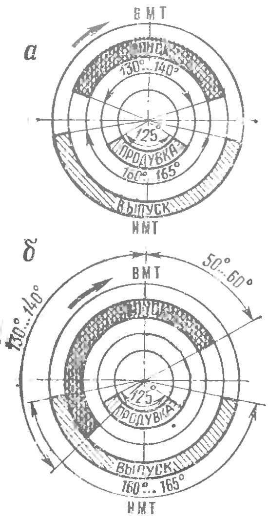
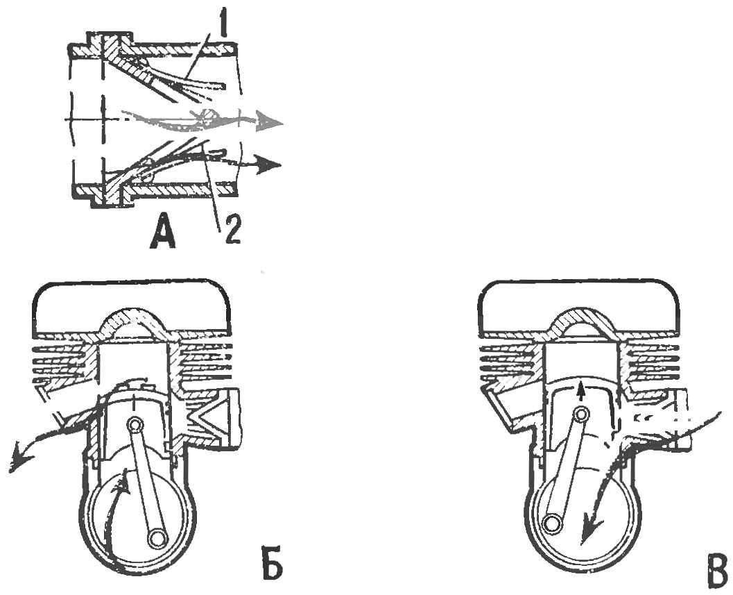
The PISTON control of the INTAKE is used on most modern two-stroke engines of consumption. The piston opens the inlet window in the cylinder, not reaching 40-60° before top dead center (TDC), and closes the window after the same 40-60° after passing TDC (with a larger value of the reverse ejection of the combustible mixture in the carburetor). The intake phase is relatively symmetric VMT and low (130-140°). On high-speed racing engines use the opening of the intake window for 65-70 before TDC, which extends the intake phase up to 150°, but degrades the engine performance at low and medium rpm. To change something for the better here is not possible, as the relative position of the edges of the window and as the piston upstroke and stroke down equally (Fig. 1A).
Fig. 1. Symmetric (top) and asymmetric (bottom) the timing of the two-stroke engine.
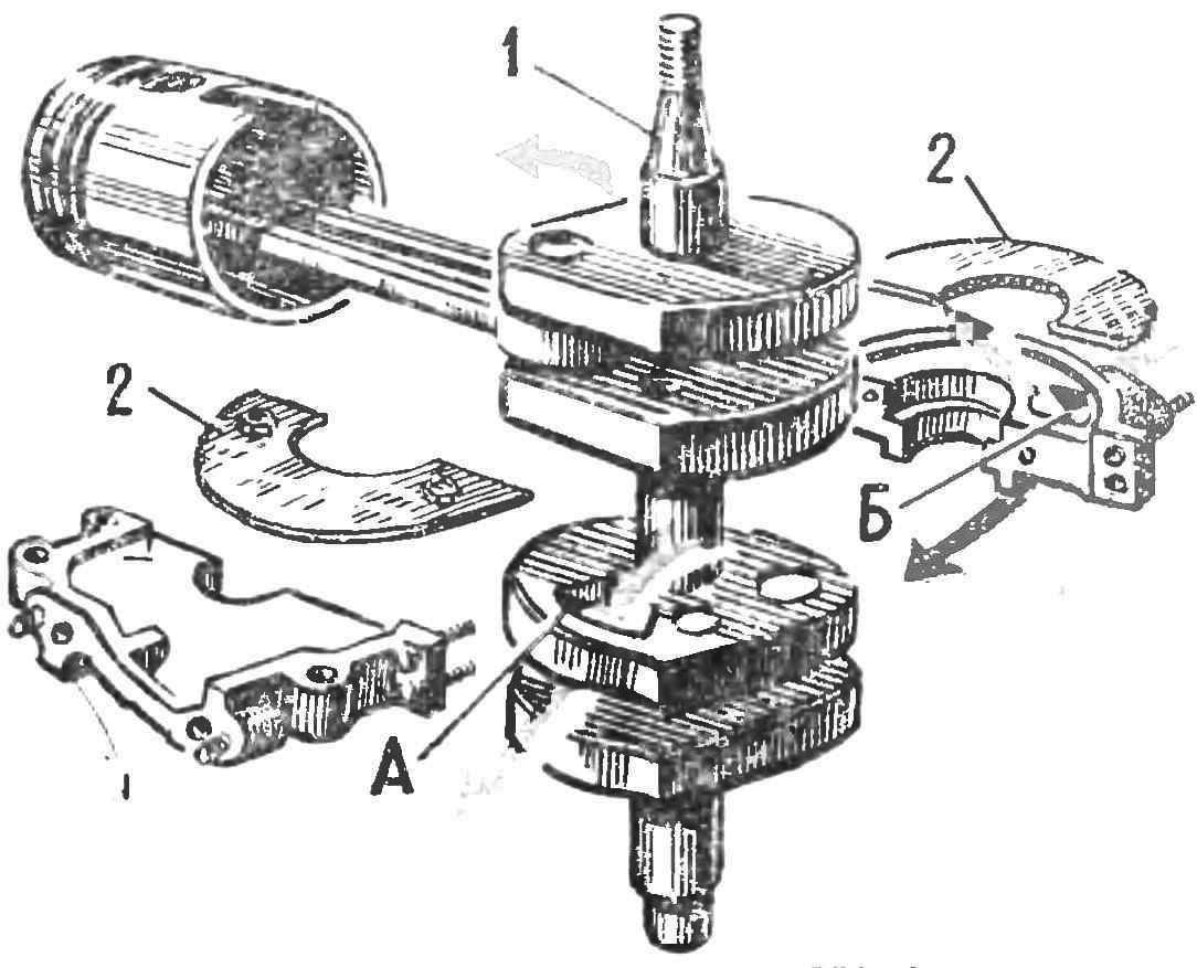
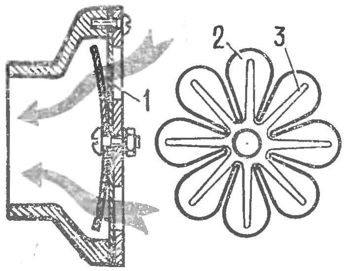
Fig. 2. The design of the control intake of the mixture of flat rotary valve (outboard motor Neptun domestic production):
1 — crankshaft, 2-2, spools, And the intake window in the crankshaft, B — inlet window in the crankcase; the colored arrows show the direction of flow of the gas mixture.
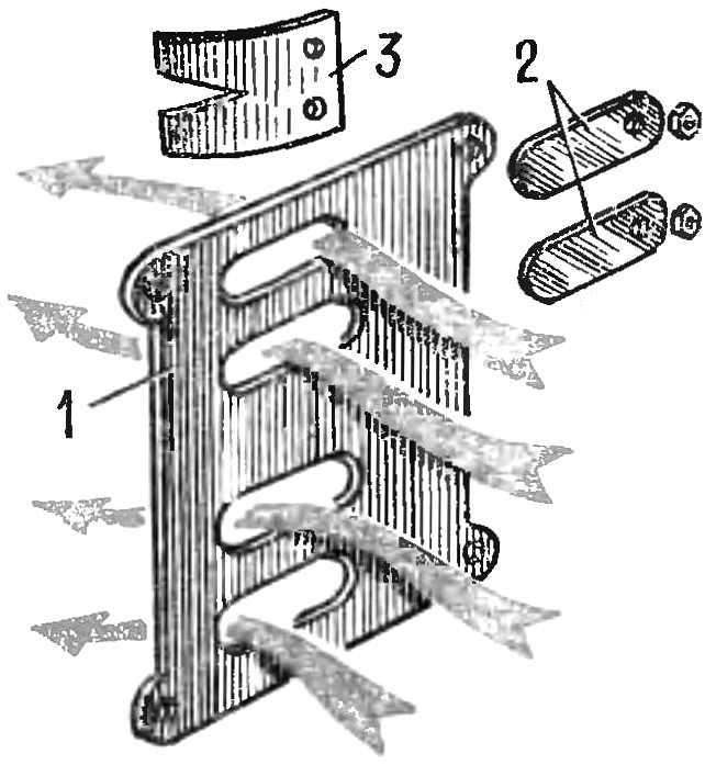
Fig. 3. Design of the intake system of outboard motor “Breeze”:
1 — flat wall, 2 — flat valves, 3 — limiter.
Reverse ejection of the combustible mixture in the atmosphere, increasing during the expansion phase of intake becomes particularly intense in the absence of Vozduhoflotsky, thereby dramatically reducing the efficiency of the engine. It should be noted that the exceptional simplicity and reliability of a piston of the intake control made this system the widest distribution of all types of two-stroke engines.
A SYSTEM.
For the filling mixture, it is desirable to begin the intake (taking into account the inertia of the gas flow) when the stroke up to a maximum of 20s of the rotation angle of the crankshaft before the piston will cover the inlet ports, that is 130-140 degrees before TDC and end at the stroke of the piston down after about 40-60° after TDC. Thus, the intake phase is not symmetrical and wide (180-200°), that is optimal (Fig. 1B). Such phase contributes to the better run, higher power density and efficiency of the engine. To obtain the most advantageous asymmetric phase of the intake valve is used and flap valves, which are particularly widespread in recent years (see “M-K”, 1974, No. 11).
To truly assess the ability of disc spools engineer D. Zimmerman of the GDR, which was successfully applied them since 1953 at MC racing motorcycles and outboard motors, have won international fame. The success of the racers, the speakers on these machines, forced to pay close attention to many of the engine builders on the disk suction system. Today, rotary disc valves are used by many foreign series-production road motorcycles and outboard motors, providing them with a litre capacity of about 110-130 HP, which was impossible with “traditional” crank-chamber blow-by.
The slide in the USSR, naturally has been successfully used on commercially available outboard motors “Whirlwind” (the spools of the PCB), “Neptune” (spool of nylon, Fig. 2) “Breeze” (spool of spring steel) and “salute” (spool of the PCB placed in a special tide Carter).
FINALLY, the VALVE SYSTEM used to obtain the asymmetric and close to the optimum intake phase. Flap valves are installed in the flow path of the mixture from the carburetor to the crank chamber and automatiseret the intake system, ensuring the stability of the income of the mixture on the entire operating speed range. Valves represent the elastic petals or plates, which under the action of vacuum in the crankcase (when the piston moves to the BMT) opens and the return stroke of the piston is closed.
There are two methods of installation of automatic flap valves: the first is the most common, when the valve is mounted directly in the crankcase between the crank chamber and the carburetor used on most outboards, most Often it is — lamellar flap valve limiters of the limb, located on the bulkhead of aluminum alloy or plastic, attached to the front of the case. The baffle is a flat (domestic motors “Breeze”, “Moscow 10”, “Surf”) or tapered (“Moscow-25”). Themselves plates of the valve are made from spring steel or beryllium bronze single (Veterok, Fig. 3), lobe (“Surf”), trehlistnyj (“Moscow 10”) and even multileaf (American motor “mercury”, Fig. 4).
Fig. 4. Multileaf suction valve American outboard motor mercury
1 — valve partition, 2 — valve, 3 — limiter.
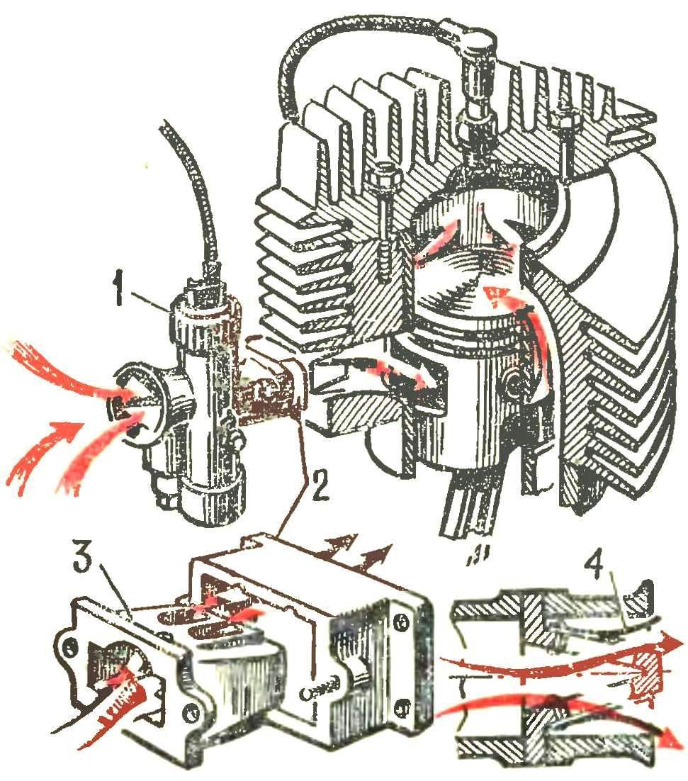
Fig. 5 structure and operation of flap valve (valve) in the engine of the Japanese firm Yamaha:
1 — carburetor, 2 — intermediate pipe, 3 — valve body, 4 — petal valve.
Fig. 6. Membrane intake engine valves Yamaha:
A — diagram of valves: 1 — delimiter, 2 — valve; — start filling the crankcase, the suction of the combustible mixture through the valves. steino into the cylinder.
If the currently used design of the inlet plate valve large litre capacities (especially in engines with small working volumes) is difficult.
The second method of placing the flap valve, less common and relatively little known, is to install a valve between the carburetor and the inlet window of the cylinder in conjunction with piston distribution. Recently, this method became very widely used on Japanese motorcycles “Yamaha” (first on race and then on road models Fig. 5). On the engine equipped with such a flap valve, the opening inlet ports of the piston is set almost the same as in the slide distribution. When you stroke it opens up the lower edge of the inlet window under the action of rarefaction in the crankcase petals open holes in the valve body. The mixture flows into the crankcase. When you move the piston down when it is relatively early to close the intake window, the petals under the action of pressure in the crankcase are pressed into the seats, stopping the access of the mixture in the crankcase. In order to prevent breakage of the valves during rejection the design includes the constraints. At moderate speeds the valves are closed quickly enough to prevent backward ejection of the combustible mixture, which improves the torque characteristics of the engine.

In engines with similar valve to improve filling, it is advisable to maintain communication between the inlet rope when the piston is near BDC. For this purpose in the wall of the piston from the inlet side provide for appropriate window (Fig. 6b). Flap valves provide added leak of the combustible mixture, when during the scavenging in the cylinders and the crankcase vacuum is formed (Fig. 6b). Design of flap valves that are applied on motorcycles “Yamaha”, has a low resistance and does not increase the volume of the crank chamber, resulting in a power density of 110— 120 BHP per litre and improved starting and throttle response at medium revs.
A. GERASHCHENKO, design engineer
Recommend to read
 INFANTRY FIGHTING VEHICLE BMP-2
In the late 1950's — early 1960-ies there has been a backlog of the USSR from Western countries in the creation of heavy tracked armored personnel carriers. During this period in the... THE TUBES BURNED OUT…
Familiar, perhaps, to every household situation: podklyuchayut all household appliances, which is in the apartment, but in the end — tube on the flap burn out from overload. More...