
The author of this material is a schoolboy from a distant Siberian city. When the editorial office received his letter describing the ski-track snowmobile he had built, he was 15 years old and studying in the tenth grade of secondary school.
Now Yevgeny has grown older, more experienced, and would probably design some components of his first all-terrain vehicle somewhat differently. But then, in his letter to the editorial office, recognizing himself as a novice in technical creativity, he asked not to judge him strictly as a designer.
Perhaps not every experienced DIYer would take on making a tracked drive, because it’s not a simple matter. It’s much easier to put a motorcycle on low-pressure pneumatics—and ride across the snowy wilderness with the wind! All the more interesting is the result of a novice’s work, who wasn’t constrained by established stereotypes and therefore wasn’t burdened by fear of failure.
I’ve dreamed since childhood of building my own all-terrain vehicle. The places here are such that it would be great to ride both in winter and summer, if only there was something to ride on.
I’ve been reading “Modelist-Konstruktor” for a long time. Getting acquainted with published designs, I noticed that authors very often take ready-made components and parts from other vehicles. So I decided to use everything I had at hand to build my machine. Namely, an engine from an Izh-Yupiter-5 motorcycle, a rubber belt, chain, sprockets, shafts, as well as various steel profiles and other materials.

I made the snowmobile frame from steel angles of various cross-sections, sheet steel, and tubes.
The frame base is a 1500×432 mm rectangle made from a steel angle with a 50x50x5 mm cross-section. I cut the ends of the horizontal flanges of the side members and the middle cross member so that after welding they would join flush with the other parts of the rectangle.
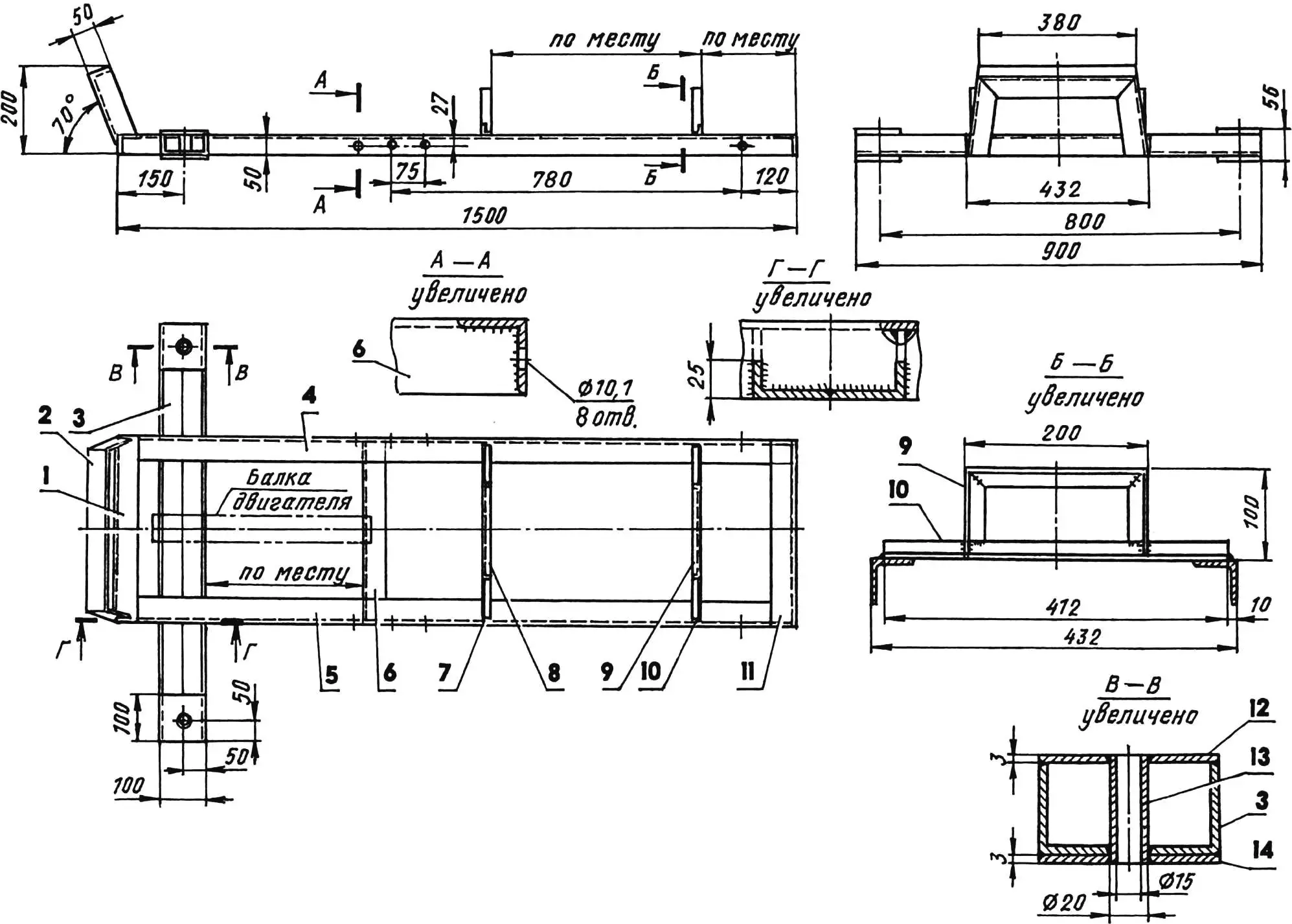
1,11 — front and rear cross members (angle 50x50x5); 2 — bumper (angle 50x50x5); 3 — steering beam (doubled angle 50x50x5); 4,5 — right and left side members (angle 50x50x5); 6 — middle cross member (angle 50x50x5); 7,10 — cross members (angle 20x20x3); 8,9 — seat supports (angle 20x20x3); 12,14 — plates (sheet s3, 4 pcs.); 13 — bushing (tube 20×2.5, 2 pcs.)
I made the steering beam separately in the form of a channel, by joining and welding the flanges of two angle segments with a 50x50x5 mm cross-section end-to-end. At the ends of the beam, top and bottom, there are 100×100 mm plates made from 3 mm thick steel sheet.
I carefully set the beam horizontally on a drilling machine; I made through holes 20 mm in diameter in the center of the plates (for ski post studs), drilling them together with the angles.

1 — snowmobile frame; 2 — post mounting (M10 bolt, 4 pcs.); 3 — post; 4 — front axle mounting (M8 bolt, 4 pcs.); 5 — drive shaft (steel, tube 20×3, L460); 6 — lock bushing (steel, tube 26×3, 2 pcs.); 7 — cotter pin (2 pcs.); 8 — bearing housing (2 pcs.); 9 — bearing 204 (2 pcs.); 10,12,15,18 — spacer bushings (steel, tube 26×3); 11 — track roller (2 pcs.); 13 — track sprocket (z = 8, t = 74.6); 14,16 — M6 sprocket mounting bolts; 17 — drive sprocket (z = 27, t = 15.875)
I marked on the rectangle and on the beam the places for their future connection and cut corresponding slots. I cut the vertical flanges of the side members at four points from below exactly to the middle of their height. I cut four matching slots 5 mm wide in the vertical flanges of the beam, on the contrary, to the middle from above, so that during subsequent welding the rectangle and beam would also join flush.
I welded a bumper made from a 50x50x5 mm angle to the front cross member; and to the side members—cross members with U-shaped seat supports—from a 20x20x3 mm angle. I attached the supports with a seat from an Izh-Yupiter-5 motorcycle pre-screwed to them in place according to my height, so it would be comfortable for me.

1 — brace (steel, sheet s3); 2 — support (steel, angle 35x35x5); 3 — connecting flange (steel, strip 20×6); 4,5 — spreader mechanism mounting lugs (steel, sheet s3)
I drilled holes in the side members for bolts mounting the posts of the front and rear axles of the tracked drive. Then between the steering beam and the middle cross member of the almost finished frame, I welded an additional channel beam with standard motorcycle engine mounting units placed on it.
1 — connecting flange (strip 20×3); 2 — housing
The most serious problems I encountered were in making the transmission and track. A lot of time was spent selecting a track sprocket, and the rubber belt also had to be chosen so it wasn’t too thin and at the same time not too thick. I had to “sweat” when calculating the length and width of the track, as well as the exact position of holes for the sprocket teeth.
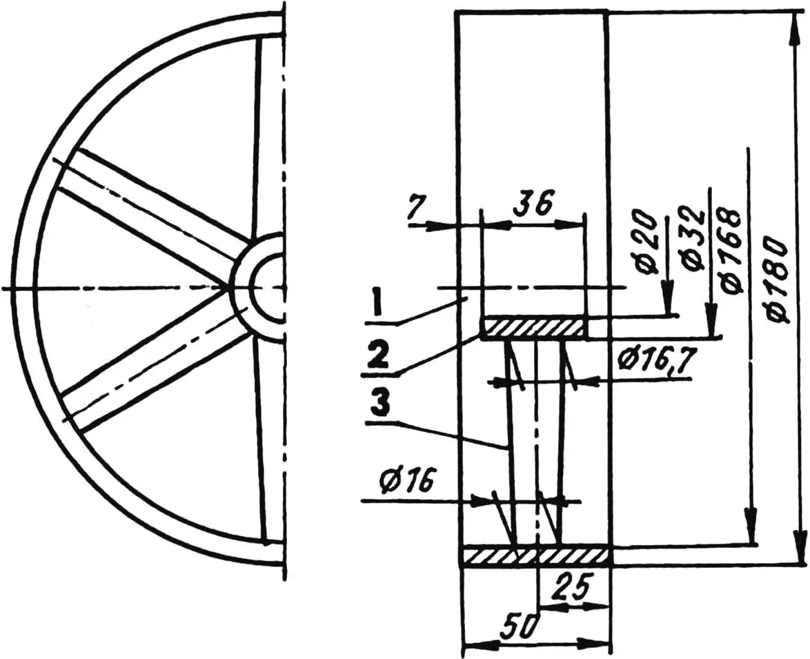
1 — drum; 2 — hub; 3 — spoke (6 pcs.)
I made the track from a rubber belt measuring 2200×300 mm and 10 mm thick. It’s joined into a ring with one stud in a “comb” type joint. And it’s tensioned by two special mechanisms located between the posts of the front and rear axles. Each tensioner consists of a tubular spreader housing and a bolt with two nuts; both the housing and the bolt have mounting bushings instead of heads.
The actual track tension occurs when the nuts on the bolts of both mechanisms are evenly tightened—both right and left. When the required tension is reached, the nuts are immediately locked with locknuts.
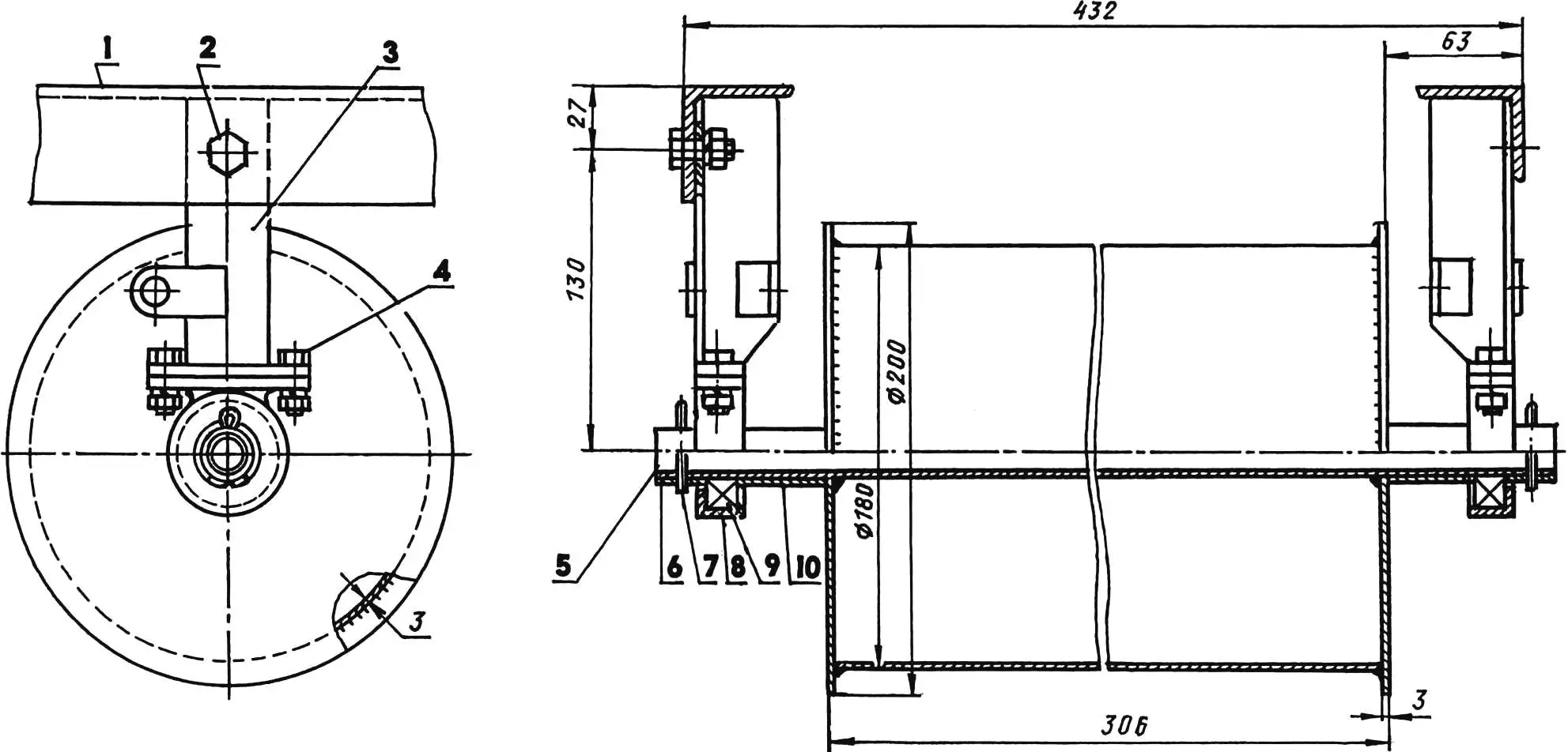
1 — snowmobile frame; 2 — post mounting (M10 bolt, 2 pcs.); 3 — post; 4 — rear axle mounting (M8 bolt, 4 pcs.); 5 — driven shaft with track drum (steel, tube 20×3, L460; sheet s3); 6 — lock bushing (steel, tube 26×3, 2 pcs.); 7 — cotter pin (2 pcs.); 8 — bearing housing (2 pcs.); 9 — bearing 204 (2 pcs.); 10 — spacer bushing (steel, tube 26×3, 2 pcs.)
I stitched the track along its entire perimeter with nylon thread to prevent its edges from delaminating. I made (more precisely—punched) holes in the rubber with a 10 mm pitch for the needle and thread using an awl. Hard work, but necessary.
I cut holes in the rubber belt for the sprocket teeth. I used the following technology. First I drilled 8 mm diameter holes, then processed them with a knife and file so they changed from cylindrical to rectangular with 14×12 mm sides. I inserted edgings cut from aluminum sheet into the resulting holes and stitched them also with nylon thread.
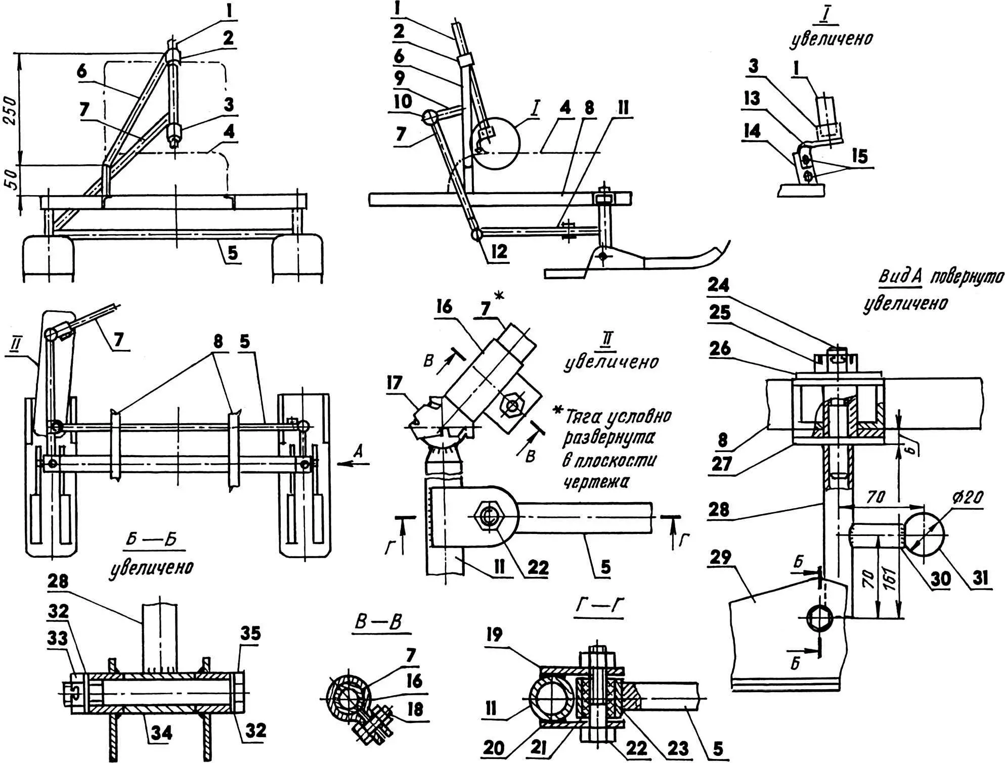
1 — steering column (steel, tube 16×2); 2,3 — bushings (steel, tube 20×2); 4 — engine outline; 5 — transverse steering rod (steel, rod Ø14); 6 — post (steel, tube 20×2); 7 — inclined steering rod (steel, tube 16×2); 8 — snowmobile frame; 9 — steering lever (steel, tube 20×2); 10,12 — ball joints; 11 — right steering arm (steel, tube 16×2); 13 — lower bushing bracket (steel, strip 20×2); 14 — engine mounting loop; 15,18,22 — M6 bolts; 16,17 — longitudinal steering rod clamp and tip; 19,20 — lugs (steel, sheet s3); 21 — plain bearing (Teflon); 23 — bearing housing (steel, tube 20×2); 24 — welded stud M14; 25,33 — castle nuts M14; 26,27 — large washers (steel, sheet s3); 28 — ski post (steel, tube 18×2); 29 — ski; 30 — left steering arm (steel, tube 16×2); 31 — joint ball; 32 — small washers; 34 — post bushing (steel, tube 20×3); 35 — M14 bolt
Between the holes I attached ground cleats to the rubber belt, which I cut from remnants of the same belt. Each ground cleat—with two countersunk head bolts. After running tests, I had to add another bolt—in the middle.
The transmission also includes front and rear axles.
The front one is the drive axle, consisting of a tubular shaft on which a track sprocket, track rollers, and a drive sprocket (from an Izh motorcycle) are mounted. The latter is intended to transmit working motion from the engine to the track.
Both sprockets are equipped with hubs cut from a tube of suitable diameter and welded into their central holes. The sprockets on the shaft are fixed with through M6 bolts (later it turned out that the nuts of these bolts need to be cottered so they don’t unscrew).
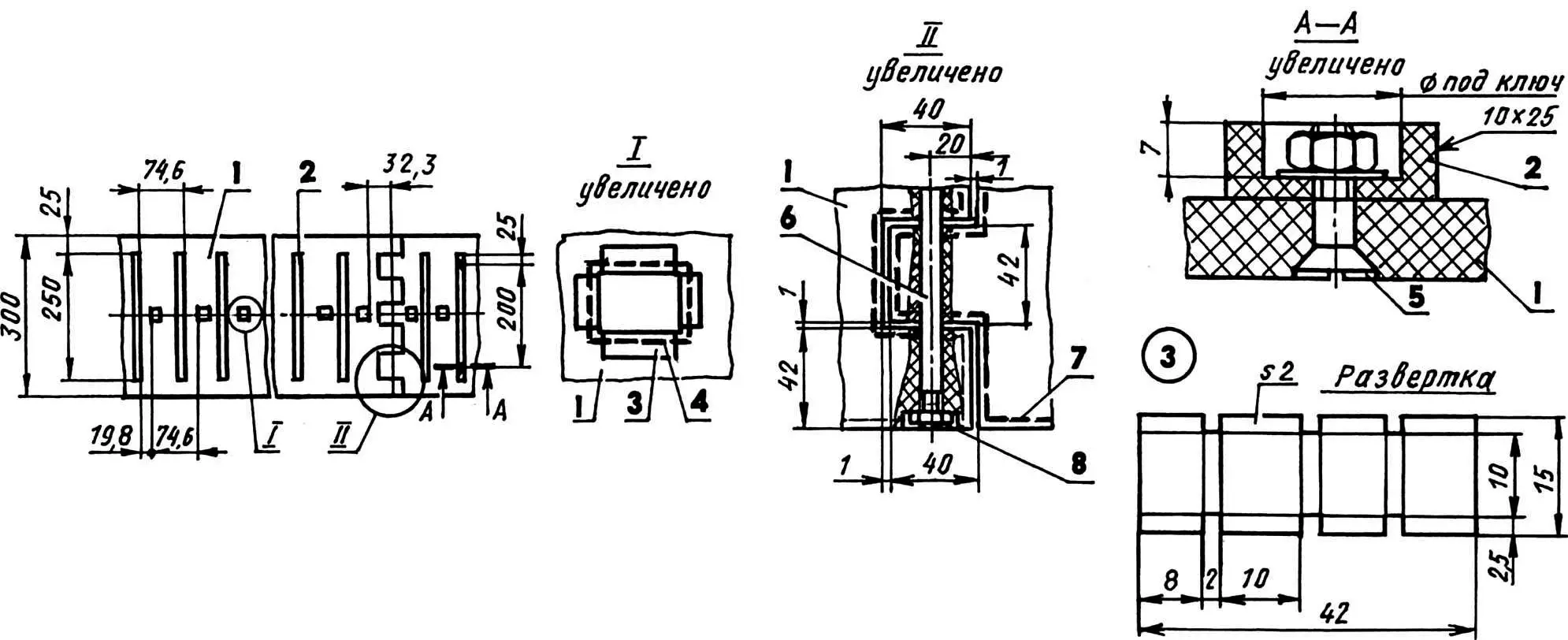
1 — track belt (rubber, strip 300×10, L2200); 2 — ground cleat (rubber, strip 25×10, L250, 28 pcs.); 3 — hole edging (aluminum, sheet s2, 29 pcs.); 4,7 — edging and track perimeter seams (nylon thread, t = 10); 5 — ground cleat mounting (M6 bolt, 56 pcs.); 6 — connecting stud M6; 8 — M8 nut (2 pcs.)
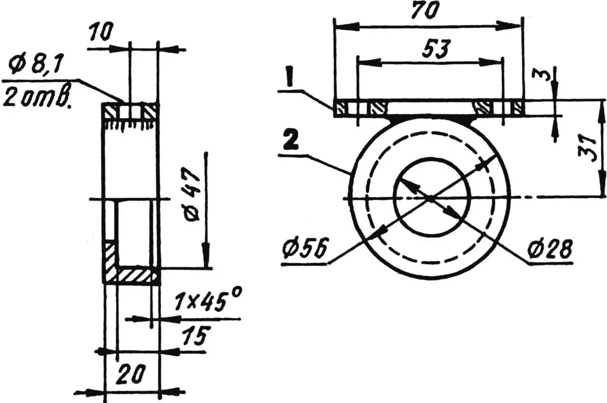
I selected the track rollers ready-made (but they can be made independently, their drawings are provided here) and mounted them on the shaft without fixation. Free spaces on the shaft are filled with spacer bushings, selected in place.
The front axle shaft rotates in two 204 bearings pressed into simple housings attached to posts, which in turn are screwed to the side members of the snowmobile frame.

1,5 — mounting bushings (steel, rod Ø23); 2 — M20 bolt; 3 — M20 nut and locknut; 4 — spreader housing (steel, tube 26×3)
The bearing housing and post designs are the same for both the front and rear axles. The difference is only that the rear posts are made without braces, as they are mounted not rigidly, but pivotally, so the track tension can be adjusted.
The rear axle consists of the same tubular shaft and track drum and is installed, like the front one, in 204 bearings with housings screwed to posts. The drum parts are cut from 3 mm thick steel sheet and permanently welded to the shaft.
The snowmobile control mechanism is a complex spatial system consisting of two skis, longitudinal and transverse rods, a post, a column, and the actual handlebar from a motorcycle with all necessary controls (throttle grip, clutch lever, etc.).

1 — frame; 2 — seat; 3 — luggage rack
The steering column is installed at the same angle as on the motorcycle and rotates in two bushings. The upper bushing is located at the end of a bent post welded to the right side member of the snowmobile frame, and the lower one, plugged from below, is attached to the engine crankcase. The control motion from the handlebar to the skis is transmitted sequentially by rods connected to each other with ball joint tips.
When making and assembling the control system, the most troublesome was choosing the ratio of lengths of the longitudinal rod and the right steering arm: it had to be done so that at any handlebar deflection the longitudinal rod wouldn’t hit the bent post.

1 — runner (steel, sheet s3); 2 — stiffening ribs (steel, angle 30x30x3); 3,7 — brackets (steel, sheet s3); 4,6 — bushings (steel, tube 20×2.5); 5,8 — undercuts (steel, angle 170x20x2)
The skis are welded from sheet steel and angles of various cross-sections and secured to the ends of posts using bolts. The ski soles are not covered with any friction-reducing material, but they should be. And it also turned out that rubber tension cords are necessary, which would prevent the ski tips from digging into the snow.
The snowmobile’s fuel tank and muffler are motorcycle standard parts; the latter is additionally secured with one bolt to the right side member of the frame.

1 — frame; 2 — seat support; 3 — seat mounting bolt (4 pcs.); 4 — seat; 5,8 — clamps (steel, strip 30×2); 6,7 — luggage rack mounting (bolts, 4 pcs.); 9 — luggage rack (steel, wire Ø5)
The luggage rack is welded from segments of steel wire and attached to the rear seat support and to the side members of the frame with two clamps made from steel strip with four bolts.
My all-terrain vehicle could be used not only in winter, but also in snowless times. For the ground version, it needs wheels instead of skis, for example, from an SZD motorized wheelchair—they’re installed instead of skis. The shaft for them needs to be the same as for the front track axle, only longer.
Finally, for full equipment, my all-terrain vehicle still lacks headlights and a trailer hitch. But that’s a matter of time.
Y. SOROKIN
Recommend to read
 ECONOMICAL VELOPLIVD
Almost all designs drive bikes have a common drawback that reduces their efficiency. This defect is uneconomical expenditure of muscular energy in the change efforts from one foot to the...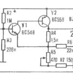 GENERATOR TREMOLO
Device, a scheme which offers the journal "Funk-shau" (Germany), is used to create different sound effects together with musical instruments. It is made in the form of a set-top box or a...
