Track mm…………………………………………………………………………………………….. 500… 700
Minimum turning radius with the bogie, mm……………………………………………. 2150
The maximum speed when transporting, km/h……………………………….. 20
Engine power (without regard to its repair), HP…………………………………………. 14
The installation space for the bearings VAPA wheels are from the bottom to the middle part of the frame rails. They look nothing like a 200-mm steel angles 36×36 mm, with appropriate holes for the bolt connection.
Swivel the hitch mechanism, as can be seen from the illustrations, consists of two side members of rectangular cross section 40×8 mm, axis-M16 bolts and beams for fastening of the workers guns, fixed elements which*are clamped in serial sockets (inner size 46×17 mm, conventionally not shown) of tractor cultivators. Moreover, each of the side members has several equidistant from each other holes 0 16 mm (conventionally not shown), designed for U-shaped clamps-clamps with thread M16 on the ends. The second end of the latter attached to the uprights of the intermediate shaft manufacture
tion which, by the way, and set him on the sprockets and bearings is not much difficulty.
The shaft of the wheel set it on nodes and details.
Here is a special mounting hubs and couplings-couplings. Transmitting the torque, is the articulation introduces a small gap — “substitute” the differential, if any, opens the kinematics, making the wheel spin free.
As shown, this ingenious mount is sufficient to perform on one wheel, and the second is to fix rigidly to the shaft by any of the well-established methods. For example, using a through bolt with a nut. Keeps well and keyway, reinforced retaining (set) screw.
In any cases, one of the hubs remains a rather complex structure, with two covers, the sleeve hitch. But the task is greatly simplified if we can get it ready the hub of agricultural machinery. Then remains only slightly counterbore the center hole in the lids up to a diameter of 40 mm and weld one side (facing the frame tillers) sleeve-coupling, made of 52 mm cut steel pipe with a wall thickness of 6 mm, having at the opposite of the axis of the machine end of the rectangular cutout. It will include the lug-hook.
Cut from the same pipe manufactured coupler-coupling; the shaft of the wheels it is fitted with bolted connection. So if necessary the progress wheel just in few minutes make free. It is enough to Unscrew the nut, pull the bolt and turn the clutch-coupling mechanism by 180°, set it in place with subsequent rigid fixing on the shaft.
Air filter homemade. Running a segment of steel pipe, wire. mesh and tin cans (see ill.). But as a filler it would work fine oiled nylon thread: Installed the air cleaner with a steel clamp, securely tighten the M5 bolt with a nut.
The muffler is homemade, too. The basis of it is made of a piece of steel pipe, which is created to exhaust a kind of “maze” made of steel 2 mm partitions. And you can strengthen them in different ways.
The most successful can consider two ways of fixing partitions. First — using the “stringing” of the steel rod stud with nuts. But this requires that the walls had a Central hole for the mount. The second way in the grooves done in the case of a pipe — casing of the muffler, where are inserted, followed by welding on the outer surface of the septum, the radius of which is increased according to the thickness of the shell wall. Except, however, the last disk partition.
To connect the muffler with the exhaust pipe is welded to the front sleeve. In fact, this is a common section of pipe with a slot and hole sizes and the exact location of which at the place of installation.
Other elements of the design of the tillers, their manufacture and mounting, it seems easy for everyone not cause. Unless, of course, to focus on the presented illustration.
For fan is the best suited small-sized motor type МЭ14-A12/15 (ГОСТ3940-84). But you can use any other, calculated to supply DC voltage of 12V. In our case, as already mentioned, working from a makeshift rectifier (see diagram), is connected directly to the generator, walking tractor. Diodes with a capacitor mounted in a plastic case and housed together with the fan itself on a special bracket.
As shown by many years of operation of the cultivator used in the design of the cooling system is significantly more effective than that which is available on motorcycles. And winning is evident in all seasons. However, in the winter to maintain optimal temperature mode of the engine it is desirable to put the fan not four-and two-blade impeller, the production of which differs little from that given in the illustrations.
The fuel tank, you can use any. Including homemade. Fuel is supplied by gravity from him. The same tank is attached to the rack intermediate shaft— steel corners for curved steel strip 40×4 mm cross-section (STZ). Bending creates additional rigidity and fits well in the layout of the whole structure in General. This same plate serves as the basis for installation in it of the instrument panel and signalov turn (when driving with a trailer truck, conventionally not shown).
The wheel control is virtually no different from those that have been published in the descriptions of improvised designs under the “Small mechanization”. These are the same two pipes of suitable cross section, curved appropriately attached thereto handles “gas” (right) and clutch (left). To impart greater rigidity to both pipes tie together the top and bottom rails. Moreover, the material for making the last… all the same pipe. Attaches the steering wheel in the lower part of the nuts and bolts directly to the frame of the cultivator.
Brake lever it is desirable to set the steering wheel to the left, just below the bottom rail. And next — the lever (pedal) switching speeds. So that when linking with the tow truck they were easy to use..
And few more features. The steering wheel in the middle of its part is attached to the upper part of a strut of the intermediate shaft by means of a round rod couplers threaded on the ends (for better durability). And the CAT switch and ignition coil are located under the fuel tank, behind the instrument panel. There is also the tensioning device of the chains.
The design of the coupling shown in the illustrations. But how to do conversation need special.
Hitch (hitch) will not fail. Because it is performed on the basis of already finished parts having a large margin of safety (head shaft drive pin-hitch), and no less reliable homemade rotary unit of the trailer (truck). The latter, in turn, consists of two coaxial thick-walled steel pipe, the diameter of which is chosen so that the contiguous surfaces work similarly angular contact ball bearing. In addition, the inner tube is simultaneously the swivel axis. And outer — drawbar, which not only serves to transmit traction forces on the cart, but also allows freedom of tilt of the latter about the axis of tillers (left or right).
The front end of the inner tube is welded to the gimbal head. On the back there thread M36 to backlash in the longitudinal direction and the corresponding attachment to weld the crossmember of trailer frame. And one more feature. To avoid rotation in the vertical plane and prevent zavalivanija hitch when turning horizontally located two finger cross braces are welded to the horizontal fork of a propeller head.
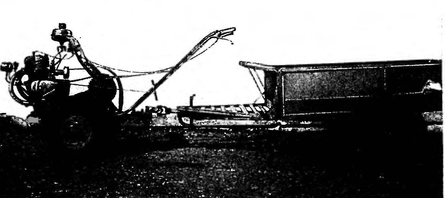
Trailing truck frame (see ill.) thanks to the inclusion of the triangle (which, as you know, the toughest figure) elements and its use as a structural material steel area is very reliable. The rectangular part is sutured lining, forming the bottom of the body. But it is possible here to use a 6-mm steel sheet. To the frame is welded on four upward Z00-mm rack steel area that serve as the basis for fixing the boards. And they, in turn, can be executed from boards and sheet steel of appropriate thickness. The rear Board is rotatable, flip-down. With clip and clamps, similar to those used on trucks.
The seat is also hinged. Fixed front swivel two triangular brackets made of 10 mm steel rod.
In the head part frame (bottom) it is desirable to provide a swivel the Parking support. As is done, for example, in the design, drawings and description of which was published in the 3rd’90.
To match the frame and rigid construction of “suspension” wheels. Shock absorbers, as can be seen from the illustrations here. To work in a field they are, on a deep belief of the author, is not needed. But it significantly increased the reliability of the whole trailer. For this reason, as a material for the manufacture of axle-spacers used round steel rod with a diameter of 40 mm. To slightly increase ground clearance trailer truck, axle shafts, wheels mounted on the brackets. They are welded to the thrust bearings and reinforced gussets out of 10 mm steel sheet.
As for the trailer wheels, then it is better to take from a decommissioned farm machinery. From our experience, we dare to say: will serve you perfectly. The more that mounted these wheels on their hubs self-aligning ball bearing.
Hiller-digger, too, can borrow from agricultural machinery. Although quite suitable and improvised construction similar to published in No. 2’86. But the bar field, it is desirable to not perform from 6 mm Sgz and use angle steel 50×50 mm. And welded to the angle 5° to the horizon, and the order of 3E— then the potato digger is on the field smoother.
For better separation of tubers from the ground should also slightly increase the length of the tooth-vytryahivanie for 10 mm on both coordinates. Then the Hiller-digger will be as shown in the illustration.
The rake (and without them — what a harvest) can easily be fabricated according to drawings and design description, published in the fourth issue of the journal for 1990. As, however, and to equip his metopomancy dozer blade (ibid.). But a plough and a harrow to do, focusing on the relevant material printed in No. 10’91.
Vladimir SOLOVYEV, the Republic of Mari El