The most important part — throttle. She experiences significant cyclic loads, therefore, its strength is subject to special requirements, as, indeed, and to the integrity of the whole engine: without accurate fitting of parts here but to do, after all, the less leakage through the gap, the higher the efficiency.
As for blades, they can be more. Importantly, the rotor with them balanced, otherwise the radial runout quickly bring him down. Appears vibration, backlash, will fall sharply power.
Fig. 1. Diagram of a rotary-vane engine:
1 — stator, 2 — rotor, 3 — rotor axis, 4 — valve, 5 — spring.
The engine is smooth-running and high rpm of the rotor. Therefore, it is indispensable where you need to ‘combine light weight and good dynamic quality.
LIKE A SQUIRREL IN A WHEEL
That, as we know, spins the wheel, quickly her legs. Wheel motor does the same thing, just two rods with rollers at the ends. It is a cylinder (Fig. 2), the piston of which moves up and down -depending on which camera — top or bottom — compressed air is supplied from a spool-type valve. With a piston rigidly connected to the rods with rollers. When the reciprocating movement of the piston, they put pressure on the notched guide wheel, causing it to rotate. The guide is made so that when the piston is at top dead center and the upper stem rests on the arch, the lower stem is located on the crest and ready to roll with it. Thus, in one revolution of the wheel the piston makes six strokes.
When you build rail, you should take into account the fact that the distance between any two diametrically opposite points is constant and equals the length of the rods to the rollers.
Fig. 2. The scheme of the pneumatic motor in the wheel:
1 — wheel, 2 — rail, 3 — cylinder, 4 a piston, 5 — stock, 6 — video.
It’s a pattern. In nature, so that the motor does not hang in the blind spots, it needs a second cylinder, placed in the same wheel, but at an angle 900 to the first. Or, if such engine is installed on the rail model, it razvivayut cylinders come in different, but connected by a common axis of the wheels of one wheelset. Profiling rails in them absolutely the same, the axes of the cylinders intersect at right angles.
Diagram of a spool-type valve is not given. It can be anything, if only the working cycle correspond to the cycle of cylinders.
The engine, according to the designer, suitable not only for direct drive of the wheels of a machine. With it, you can get more speed if you use this engine as a flywheel and a torque transfer shaft or the friction gear.
ON THE ENDLESS ROAD…
Connecting rod free piston engine work similar to a three-blade fan is the same noise and the flickering of parts of the blade… But there is nothing like pneumatic cylinders, and all around them the protective ring, and guide ring carefully selected shape (figure 3).
In the center on the axis of the engine located washers: stationary distribution and rotating. Compressed air through the nozzle, and supply channels of the first washer goes to the second in which the display tube of the air supply and the cylinders. Once the holes of two adjacent tubes alternately (short time interval) coincide with the supply channels, the air rushes into the cylinders and forces pistons to move. In the way of their rod guide ring, the rod rested in his videos (active phase) and sliding in the direction of least resistance, turn the rotor of the motor.
Fig. 3. Diagram of connecting rod free piston engine:
1 — frame, 2 — guide ring, 3 — cylinder, 4 — piston rod with roller, 5 — base of the rotor 6 and rotating shaft 7 of the distribution disc, 8 — shaft PTO, 9 — nozzle, 10 — supplying channel, 11 — exhaust sector.
At the end of the active portion of the tube ahead of the piston is moved from the supply channel to the exhaust distribution sector goals and guide ring (passive phase) returns the piston to its original position. At this time the rotor is rotated the other two pistons.
The engine is the essence of the previous development, the wheel. But if there spinning wheel and this motor remains stationary, here the opposite is true. However, to make it compact is unlikely due to the bulkiness of the idler.
The TROIKA
As in the famous Russian Troika — three horses in harness, three cylinder in the Cam-piston engine all its power put into rotation of the output shaft. Only instead of horse harness here the rollers, the Cam bushing and pinion. From the classic this engine is characterized in that the cylinders he has, but Krivosheenko mechanism. The reciprocating movement of the pistons therein is converted into rotational motion of the output shaft with the help of Cam rollers and bushings (Fig. 4).
The rollers located on the crossbar of the T-shaped piston rod. The ends of the bars enter the vertical slots in the walls of the crankcase, which serve as guides for stocks and do not allow the pistons to rotate in the cylinders. “Slipping” on the knuckles of the profiled rollers cause them to rotate around its axis (if cylindrical Cam surface to deploy on the plane, then his profile will appear as a sine wave).
Fig. 4. Scheme of the Cam-piston engine:
1 — cylinder, 2 — cylinder, 3 — piston, 4 — stock, 5 — groove, 6 — roller, 7 — Cam with the gear, 8 — Carter, 9 — angular contact ball bearing, 10 — bottom of crankcase, 11 — PTO.
So, rotating each sleeve with the gear, the pistons, crank and output shaft. Quickly and evenly, because for one revolution of the shaft receives from the pistons six pulses!
To work such an engine may as on a conventional liquid fuel (then he needs a system power supply, ignition and distribution of the combustible mixture) and compressed gas (in this case a spool-type valve).
Coefficient’ of the action of the Cam-piston engine is higher than that of the engine crank mechanism: it is much less friction losses in the cylinder and in the bearings. The application should be expected not only in the models. Engine fed with compressed air from auxiliary cylinders can be more than, let’s say, for drive wheels, single, double pneumobilia. It does answer those who are attracted to all new and unusual.
Working models of most of their designs A. S. Abramov gave CSUT of the RSFSR with the hope that the younger generation will take up the baton of creativity that will improve its technical findings and will make some contribution to the development of domestic technology.
Recommend to read COMFORT BEGINS WITH A HANGER You enter into your apartment, whether to visit, the first thing that greets you when you walk through the door, the hallway or the front, as it is called. In modern homes it is usually... THE LIGHT IN THE SWITCH Not to look for the switch in the dark, to make it a backlit "Neonka" from the starter of the fluorescent lights and the resistor 100 ohms, connected in series— that's the whole scheme.... 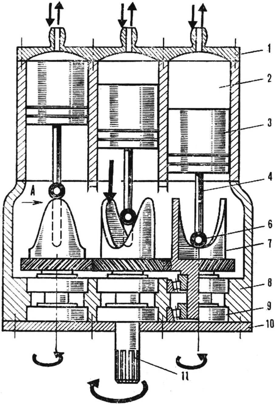
 The readers of our magazine are familiar according to previous publications the name of the Moscow designer-lover of Alexander Abramov. Despite his advanced age (he is now 85 years old), he continues to be active creative activity. In his home lab many layouts, working models and full-scale models of various mechanisms, including engines. Alexander invented and built dozens of them. Many of the designs are unusual and contain original ideas. But the author does not jealously protect their technological innovations from third-party curious look, but rather generously shares with all who show interest in its development. So this time, inventing and testing a few new arrangements, Alexander makes some of them to the reader’s judgment.