From the history of automotive engineering, it is known that the first automobile was K. Benz’s three-wheeled carriage. Later, with the increase in speeds, it was replaced by a four-wheeled vehicle, as more stable in turns. However, designers did not abandon the desire to create a three-wheeled chassis of the same stability. It is structurally simpler and lighter with the same passenger capacity, therefore more reliable and cheaper to operate. Obviously, the German company “Daimler-Benz” proceeded from the same considerations when designing the unusual two-seater “Life-Jet” F-300 on three wheels, presented at the end of 1997 at the Frankfurt Motor Show. Specialists and just visitors to the exhibition wondered for a long time — is it a car or a motorcycle? In terms of design simplicity, the novelty really approached a motorcycle, while its hydraulic and electronic equipment solved the issue of stability in turns at any speeds, like a four-wheeled car.
The appearance of the “Life-Jet” F-300 was not accidental. Increasing maneuverability in city traffic jams, simplifying the design and reducing costs — these are the problems that incline specialists from different countries to work on this type of transport.
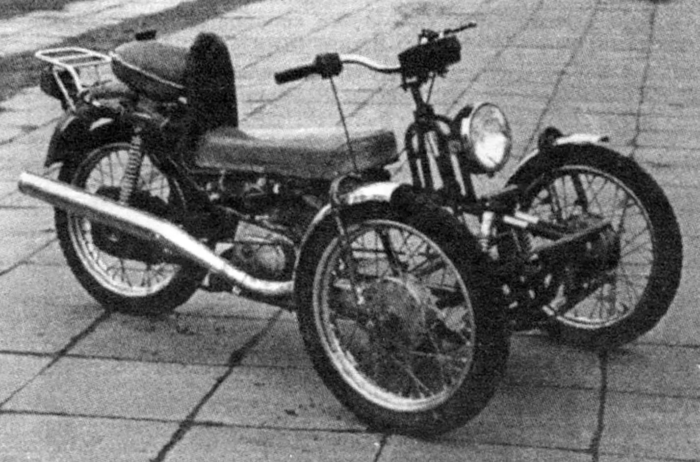
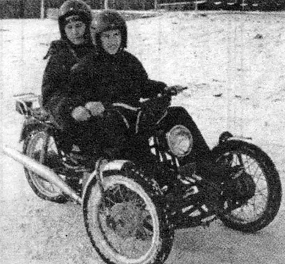
When designing his three-wheeled motorcycle (hereinafter tricycle), the author pursued a more modest goal — to make it light and all-weather. The choice of the layout scheme was suggested by the experience of operating three-wheeled velomobiles, which were manufactured by high school students in the Minsk Palace of Children and Youth in the early 90s (at that time the author headed the workshop “Design of biotransport and motor vehicles” there). Thanks to the simplicity of the design, the velomobiles turned out to be reliable, light (about 18 kg) and, given their low speed, stable in turns. Therefore, the experimental (in the photo), and then the second — refined (in the drawing) samples of the tricycle were made according to the velomobile scheme: two steerable wheels in front and one driving wheel in the rear. Consequently, there is no differential and complex rear suspension of the automotive type.
The issue of tricycle stability was solved (partially) already during the design and manufacture of the first sample. Its driver, when turning, tilted the main part of the machine (together with the engine and rear wheel) to one side or the other, as on a bicycle, and thus parried the action of centrifugal force. For additional insurance, he could additionally rest his foot against the front axle cross member.
With the installation of the cabin, resting the foot against the front axle became impossible, a lever was needed that, depending on the direction of the turn, would transmit force to the right or left side of the axle.
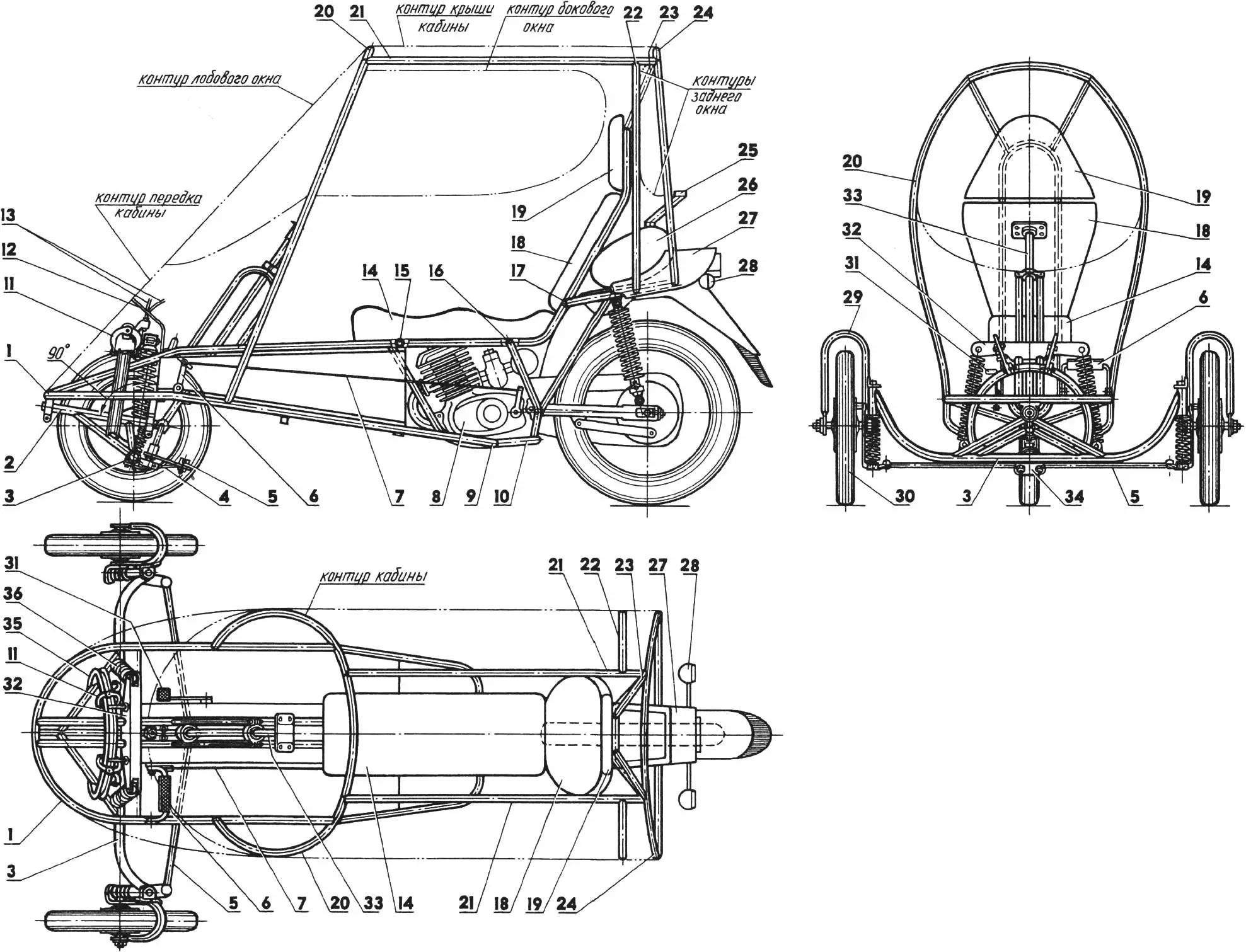
1 — tricycle frame; 2 — roll mechanism shaft; 3 — front axle; 4 — steering arm, right; 5 — steering rod, left; 6 — gear shift pedal; 7 — gear shift rod; 8 — engine (not shown on front view); 9,15,16,17 — welding points of tricycle frame with motorcycle frame; 10 — motorcycle frame (cut); 11 — caliper brakes; 12 — sheathing (not shown on front and top views); 13 — caliper brake drive cables of roll mechanism; 14 — seat cushion; 18 — backrest; 19 — headrest; 20 — cabin frame arc, front; 21 — side panels; 22 — cabin frame arc, middle; 23 — struts; 24 — cabin frame arc, rear; 25 — fuel tank filler neck; 26 — fuel tank (from moped); 27 — end cap (motorcycle fairing element); 28 — rear lights (from motorcycle); 29 — front suspension fork; 30 — wheel from moped; 31 — wheel brake pedal; 32 — caliper brake and roll mechanism damper rocker; 33 — steering column shaft (handlebar not shown); 34 — steering arm, central; 35 — roll mechanism rim, brake; 36 — roll mechanism damper.
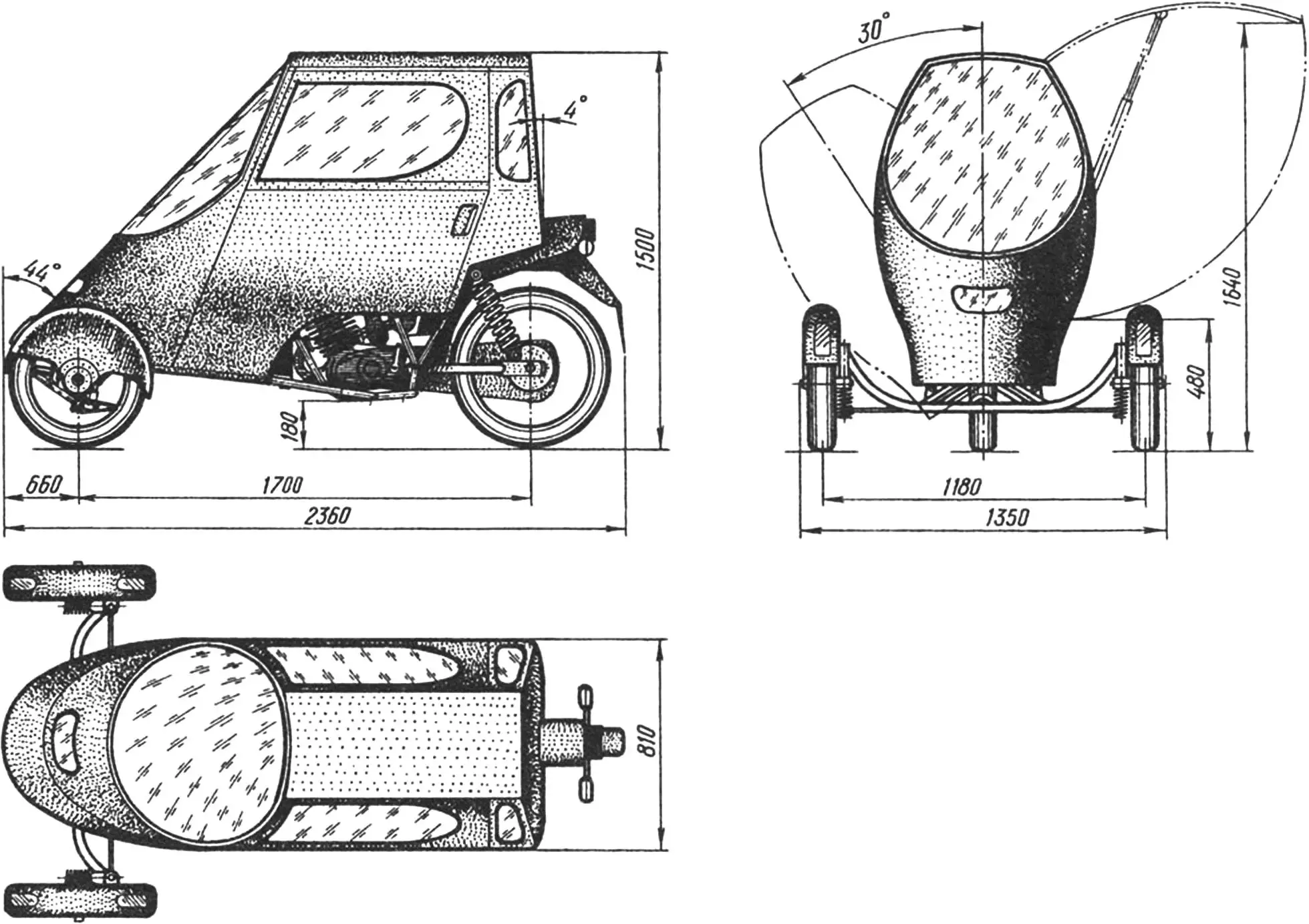
However, it is possible to do without a lever. The driver of the refined tricycle, before entering a turn, needs to tilt the movable part of the machine (at an angle of no more than 30°) and fix it with a caliper-type brake device (from a sports bicycle), which is located on the front axle; and after exiting the turn, release the brake-lock. The springs of the roll mechanism will return the machine to a vertical position by themselves.
Other shortcomings of the experimental sample were also taken into account. In particular, the front axle was lightened (wheels from a moped with tires size 65-405 were used) and unloaded (base increased), which improved longitudinal stability and made it possible to lengthen the seat. A streamlined cabin was installed, and its frame is connected to the tricycle frame, forming a single load-bearing structure with it. A brake-lock of the roll mechanism was introduced, as already mentioned. And finally, the foot engine start was replaced with a manual one: the standard lever was partially cut and extended with a tube about half a meter long.
As the basis of the described development, units, assemblies and parts of the serial two-wheeled motorcycle MMBЗ-3.113 were used. Its frame is cut from the front and top, and the remaining part is welded to the tricycle frame, made mainly from so-called bicycle tubes of various diameters.
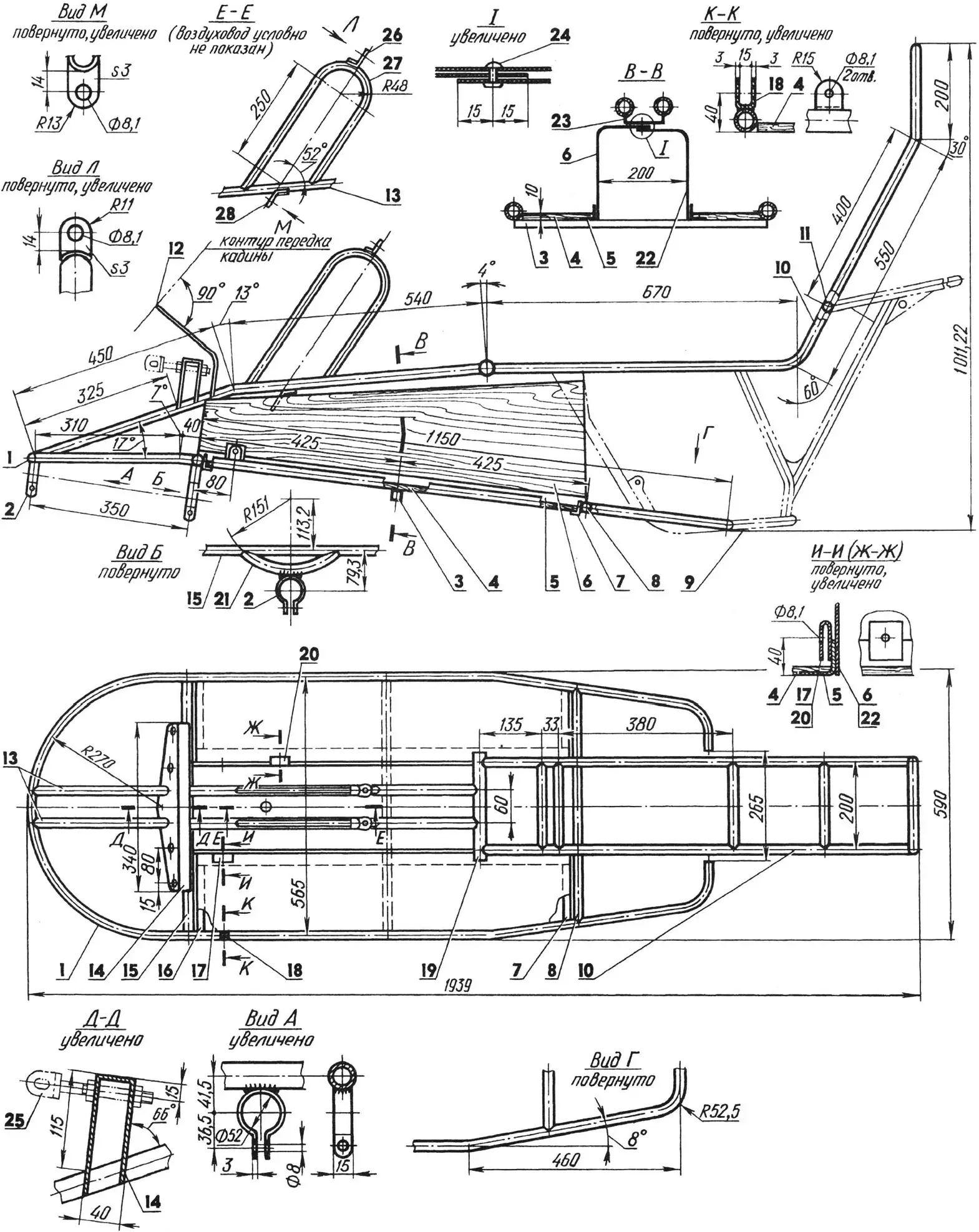
1 — base (tube 25×2); 2 — roll mechanism bearing clamps (steel, strip s3); 3 — footrest support (tube 25x25x2); 4 — footrest (plywood s10, 2 pcs.); 5 — footrest bracket, longitudinal (bent angle 40x40x3, 2 pcs.); 6,22 — air duct walls (steel, sheet s1,5); 7,16 — footrest brackets, transverse (angle 25×25); 8 — rear cross member (tube 25×2); 9 — part of motorcycle frame ММВЗ-3.113 used in tricycle construction; 10 — seat frame (tube 25×1,5); 11 — crosspiece (tube 25×1,5, 4 pcs.); 12 — sheathing (steel, sheet s1, not shown on top view); 13 — side members (tube 25×1,5); 14 — caliper brake and roll mechanism damper rocker (steel, sheet s3); 15 — front cross member (tube 25×2); 17,18 — gear shift pedal brackets, inner (standard from motorcycle ММВЗ-3.113) and outer (steel, sheet s3); 19 — bottom bracket (tube 30×2); 20 — brake pedal bracket (standard from motorcycle ММВЗ-3.113); 21 — roll mechanism mounting arc (tube 25×2); 23 — air duct mounting bracket (steel, sheet s1,5); 24 — rivet Ø3 (rivet seam pitch 30 mm); 25 — M8 bolt with caliper brake mounting loop (2 pcs.); 26,28 — steering column shaft bearing mounting loops (steel, sheet s3, 4 pcs.); 27 — steering column post (tube 20×1,5, 2 pcs.).
The base of the tricycle frame is bent from a long tube section, but can be made from several shorter sections. At the front, the first roll mechanism bearing clamp and side members are welded to it; at the bottom, to the front cross member — a tubular arc with the second roll mechanism bearing clamp and footrest support; at the rear — by brackets of its footrests — the used part of the serial motorcycle ММВЗ-3.113 frame.
The frame side members carry the rocker — a U-shaped bracket bent from a steel sheet with holes for caliper brake and roll damper mounting bolts — and two inclined tubular steering column posts. The ends of the side members are joined with the seat frame bottom bracket, to the crosspieces of which — by its cut tubes — the used part of the ММВЗ-3.113 frame is welded.
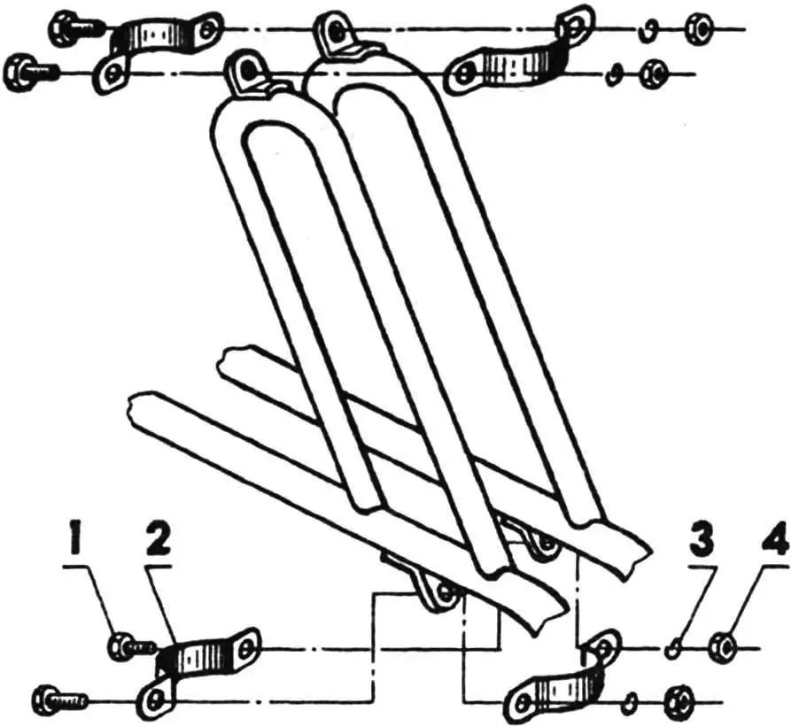
1 — M8 bolt (4 pcs.); 2 — bracket (steel, sheet s3, 4 pcs.); 3 — spring washer (4 pcs.); 4 — M8 nut (4 pcs.).
A tunnel is arranged between the base and side members of the tricycle frame, directing the air flow to the engine head — for cooling. The air duct walls are made of steel sheet. At the top they are riveted to a long bracket (from the same sheet), and at the bottom welded to longitudinal angles, extending from the front to the rear cross member. Footrests made of thick, linseed oil-impregnated plywood, covered with ribbed rubber mats, are attached to the angles (longitudinal and transverse) with screws.
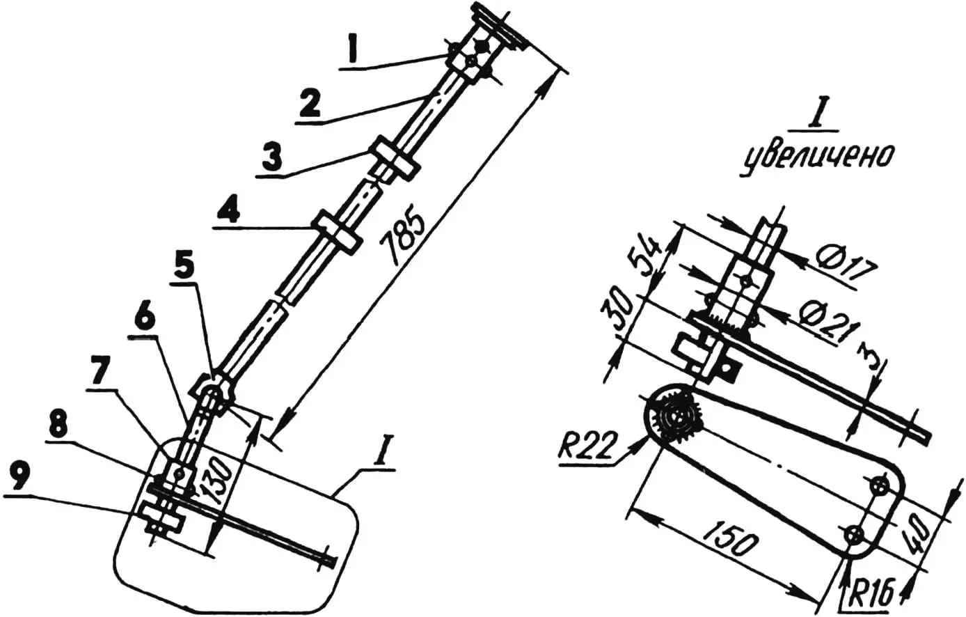
Some steering parts of the tricycle are borrowed. For example, the steering column shaft with handlebar mounting bracket (on the tricycle it is from ММВЗ-3.113) and steering rods with ball joints — from a sports kart, and the universal joint — from a passenger car.
Ball bearings are fitted on the steering column with interference and attached to the angular loops of the posts using brackets and bolts. The universal joint shaft bearing is clamped in a clamp welded to a spacer on the front axle beam.
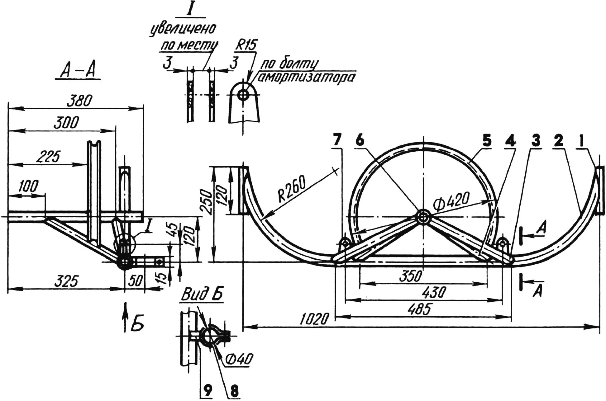
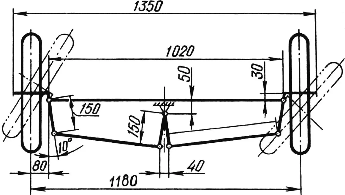
1 — kingpin bushing (tube 21×1); 2 — beam (tube 38×2); 3,4 — struts (tube 25×2); 5 — roll mechanism rim, brake (part of bicycle rim); 6 — roll mechanism shaft (tube 25×2); 7 — roll mechanism damper mounting fork (steel, sheet s3); 8 — steering column universal joint bearing clamp (steel, sheet s3); 9 — spacer (tube 50x25x2).
The front axle is assembled mainly from tubes. Its main element is the beam, to which struts with the roll mechanism shaft and brake rim, damper mounting loops, a spacer with bearing clamp and kingpin bushings are welded.
The tricycle body roll is performed around the axis of this very shaft. If we mentally extend the axis backward, we will see that it is directed strictly to the point of contact of the rear wheel with the ground. Such a coincidence is not accidental — it is the key to the correct operation of the entire roll mechanism.
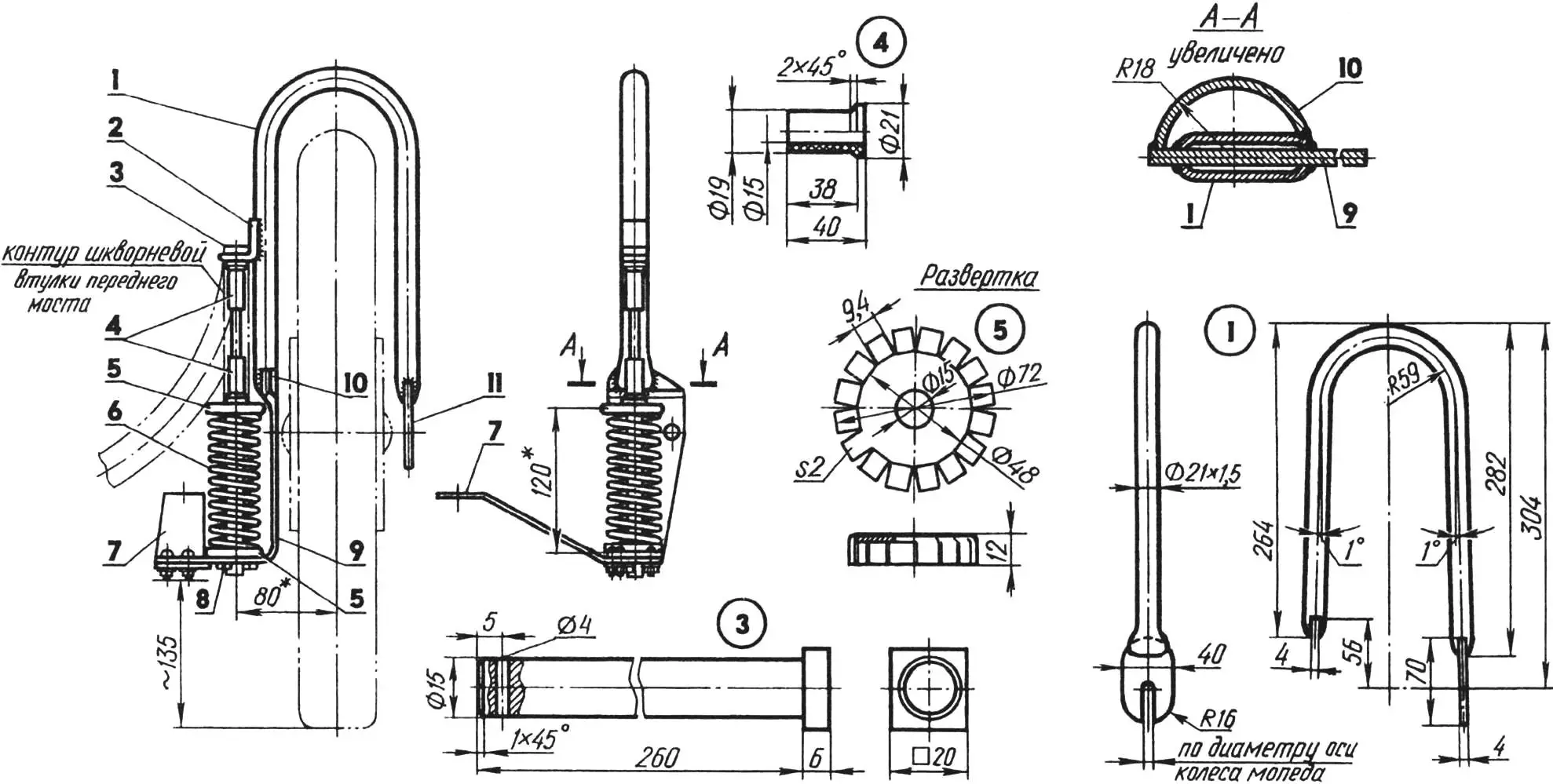
1 — fork (tube 21×1,5); 2 — stop (steel, sheet s6); 3 — kingpin; 4 — bushings (Teflon, bronze can be used); 5 — cups (steel, sheet s2); 6 — spring (from rear damper of motorcycle ММВЗ-3.113); 7 — steering arm; 8 — cotter pin Ø4; 9 — bracket; 10 — wheel brake mechanism segment; 11 — tip (steel, sheet s4).
Ball bearings are fitted on the shaft ends with interference and enclosed in clamps on the tricycle frame.
The part of the bicycle rim welded to the front struts of the axle is the object of application of forces of the caliper brakes when fixing the roll mechanism on turns. After passing the turn, the tricycle body is returned to a vertical position by two rear dampers (from a serial motorcycle). Their upper ends are connected to the fixed rocker, and the lower ones — to the loops on the front axle beam.
1 — handlebar mounting bracket (from sports kart); 2 — steering column shaft (from sports kart, tube 17×1,5 can be used); 3,4,9 — bearings 203; 5 — universal joint (from passenger car steering column); 6 — universal joint link shaft (tube 17×1,5); 7 — steering arm, central; 8 — rivet (Ø3, 4 pcs.).
The front suspensions are made in the form of spring-loaded tubular forks. The forks are connected to the front axle kingpin bushings with long bolts — kingpins. Teflon bushings (two per kingpin) are used as plain bearings, but bronze ones will also work.
Springs enclosed in homemade cups serve as dampers. They are taken from motorcycle rear dampers. Their length is such that the suspension travel along the kingpin axis is 60 mm.
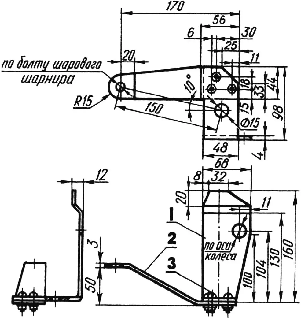
1 — bracket (steel, sheet s4); 2 — arm (steel, sheet s3); 3 — M5 bolt (3 pcs.).
Brackets welded to the flattened ends of the forks are fastened with bolts to the steering arms. The latter are hingedly connected by rods to the central steering arm, which receives control impulses from the steering shaft through the universal joint link.
The front wheels of the tricycle are from a moped. They are fully unified, since during assembly they are mounted in the forks with their half-axles without modification. However, such half-axles will not withstand any load. Therefore, it is advisable to replace them with cone-shaped ones with thickening towards the inner bearing (the diameter of this bearing should be 2—4 mm larger than the outer one).
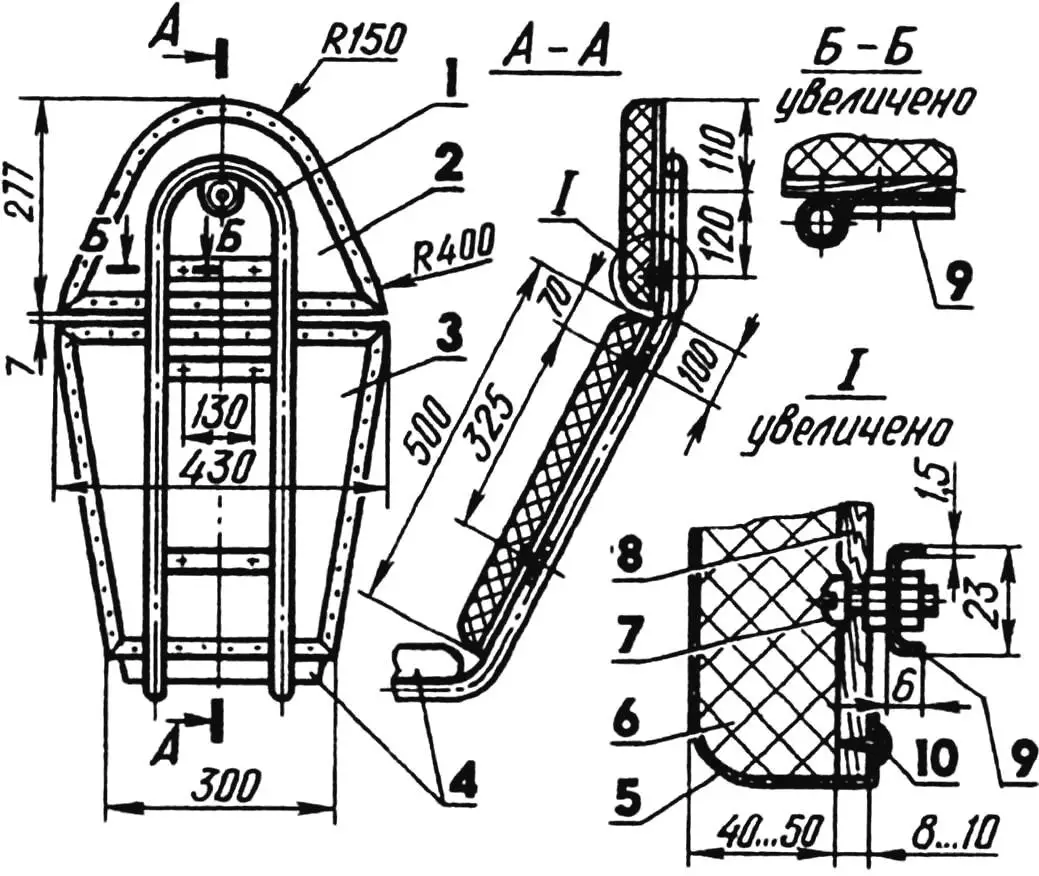
1 — seat frame; 2 — headrest; 3 — backrest; 4 — driver and passenger seat (from motorcycle ММВЗ-3.113); 5 — upholstery (artificial leather); 6 — filler (foam s40…50); 7 — M5 bolt (7 pcs.); 8 — base (plywood s8…10); 9 — bracket (bent U-shaped profile, 3 pcs.); 10 — upholstery nail (along contour with pitch 30 mm).
The driver and passenger seat is motorcycle — from MMB3-3.113. The seat backrest is homemade. Their device is detailed in the drawing.
The cabin frame consists of tubular arcs and side panels, connected to each other and to the tricycle frame by welding. A tricycle is not a homemade car, the technical requirements for which contain a ban on installing a plastic windshield. Therefore, the cabin is lined on all sides (except the bottom, of course) with organic glass 2.5 mm thick.
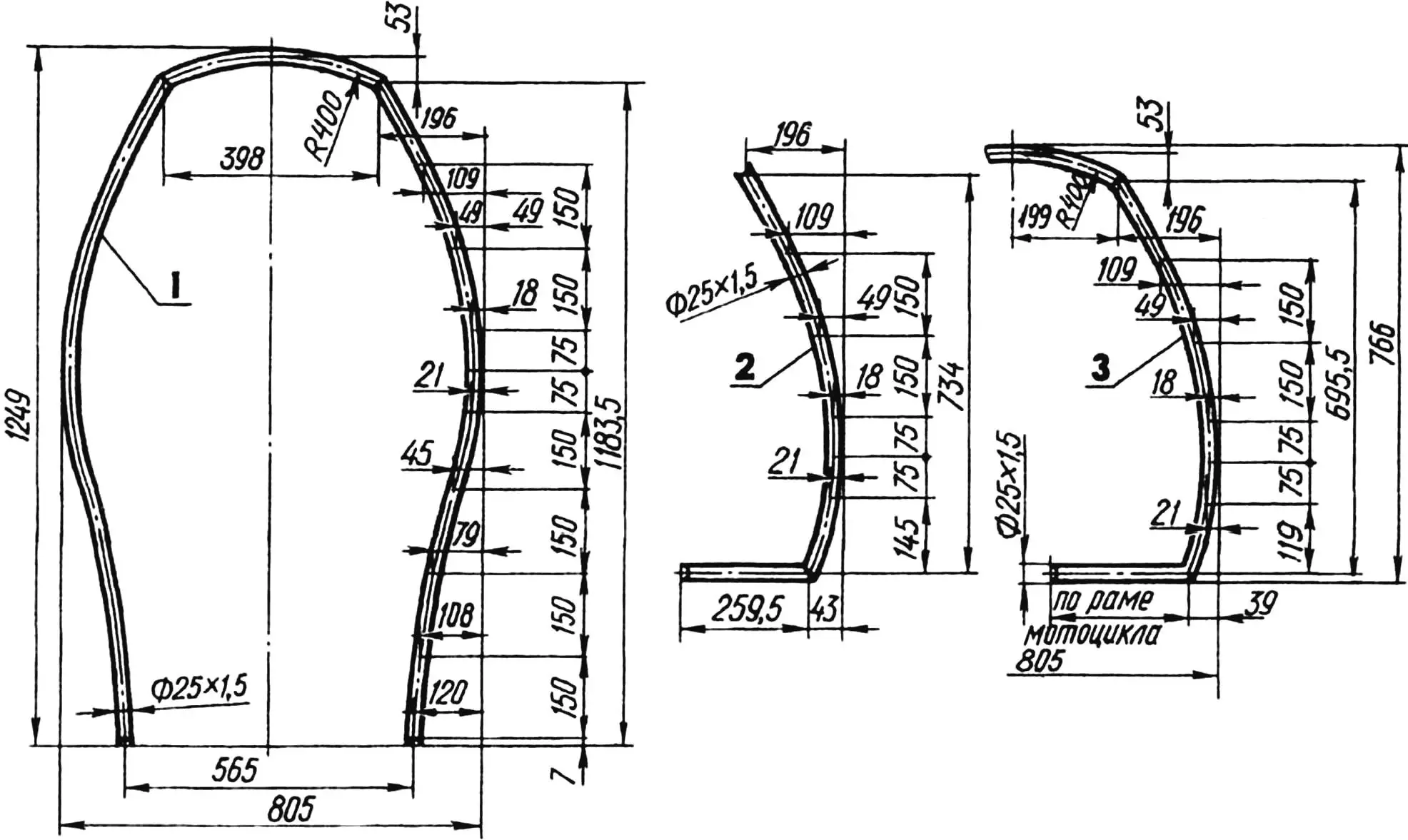
1 — front (tube 25х1,5); 2 — middle (tube 25×1,5, 2 pcs.); 3 — rear (tube 25×1,5).
The windshield has complex spatial contours, so it is formed on a wooden master model with heating by a gas torch. The roof, rear and side panels do not need forming, since they are formed by straight lines. They are attached to loops welded to the frame arcs and side panels with small bolts through rubber seals.
On the left side, the cabin has an upward-opening door with a telescopic holder similar to those used on the rear doors of hatchback cars. The door rotates on two horizontal axes screwed into the front and middle frame arcs. In the closed position, it is fixed by a mechanical lock hidden in the armrest panel. When the lock handle is turned, pins extend from the panel and enter the corresponding holes in the frame arcs.
The cabin is not completely transparent: the areas necessary for the driver for normal visibility are left untouched, and everything else is painted. And from the inside. Thus, on the one hand, the shiny external surface of the organic glass is preserved, and on the other — the familiar human visual perception of the cabin as such.
D. SHAVEYKO
Recommend to read
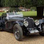 TRIUMPH DOLOMITE-8
English automobile firm Triumph, founded in 1901 in Coventry Austrian immigrant Siegfried Betmenom until 1923 was manufacturing motorcycles. The first car company became TRIUMPH 10/12НР...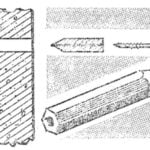 THE PENCIL
What do we do when we need something to hang on a concrete wall? Bore a hole and hammering the tube, usually wood. And where is the guarantee that the tree got dried? Often, the tube...
